

Page 1
Instructions Manual
Manual de instrucciones
Manual de Instruções
EFC 9542
Page 2

EN
Instructions Manual
INDEX
RECOMMENDATIONS AND SUGGESTIONS......................................................................................................................5
CHARACTERISTICS..............................................................................................................................................................6
INSTALLATION ......................................................................................................................................................................7
USE.......................................................................................................................................................................................10
MAINTENANCE....................................................................................................................................................................12
2
2
Page 3

ES
Manual de instrucciones
ÍNDICE
CONSEJOS Y SUGERENCIAS ...........................................................................................................................................14
CARACTERÍSTICAS............................................................................................................................................................15
INSTALACIÓN......................................................................................................................................................................16
USO......................................................................................................................................................................................19
MANTENIMIENTO................................................................................................................................................................21
3
3
Page 4

PT
Manual de Instruções
ÍNDICE
CONSELHOS E SUGESTÕES............................................................................................................................................23
CARACTERÍSTICAS............................................................................................................................................................24
INSTALAÇÃO.......................................................................................................................................................................25
UTILIZAÇÃO.........................................................................................................................................................................28
MANUTENÇÃO....................................................................................................................................................................30
4
4
Page 5
EN
RECOMMENDATIONS AND SUGGESTIONS
INSTALLATION
• The manufacturer will not be held liable for any damages resulting
from incorrect or improper installation.
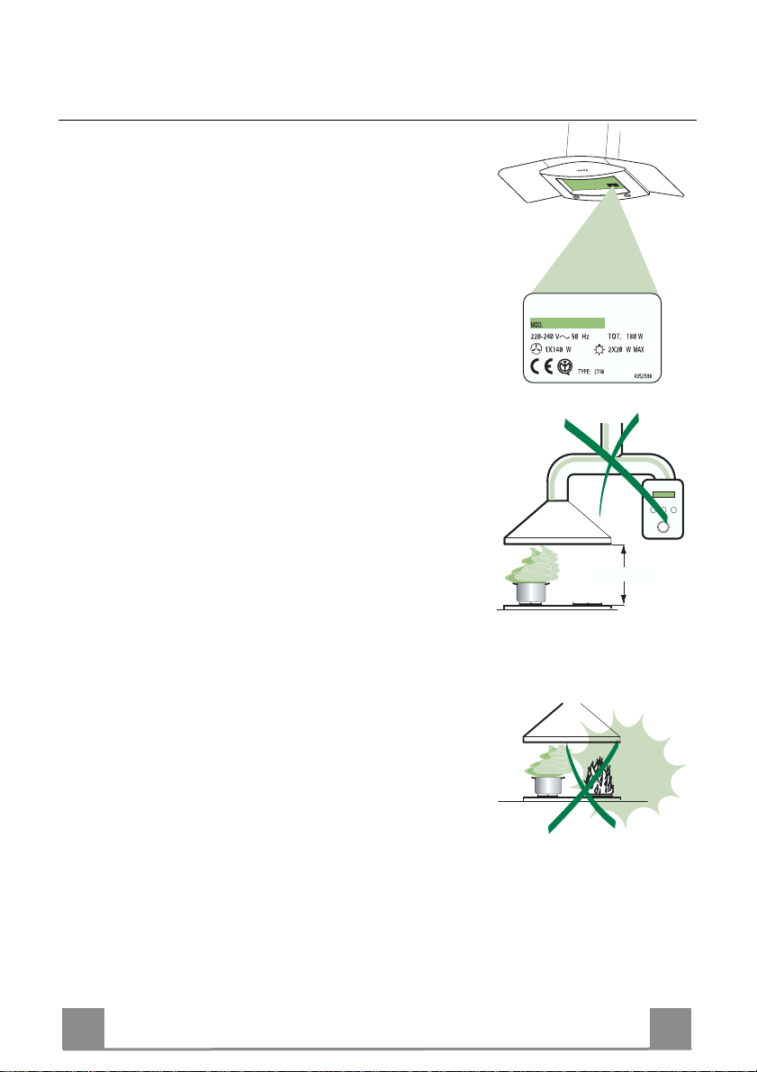
• The minimum safety distance between the cooker top and the extrac tor hood is 650 mm.
• Check that the mains voltage corresponds to that indicated on the
rating plate fixed to the inside of the hood.
• For Class I applianc es, c heck t hat th e domes tic po wer suppl y gua rantees adequate earthing.
Connect the extractor to the ex haust flue through a pi pe of minimum
diameter 120 mm. The route of the flue must be as short as possible.
• Do not connect the extractor hood to exhaust ducts carryi ng combustion fumes (boilers, fireplaces, etc.).
• If the extractor is used in conj unction with non-electrical appliances
(e.g. gas burning appliances), a suffici ent degree of aeration must be
guaranteed in the room in order to prevent the backflow of exhaust
gas. The kitchen must have an opening communicating directl y with
the open air in order to guarantee the entry of clean air.
USE
• The extractor hood has been designe d ex cl usi vely for domesti c us e to
eliminate kitchen smells.
• Never use the hood for purposes ot her than for which it has ben designed.
• Never leave high naked flames under the hood when it is in operation.
• Adjust the flame intensity to direct it onto the bottom of the pan only,
making sure that it does not engulf the sides.
• Deep fat fryers must be continuously monitored during use: overheated oil can burst into flames.
• The hood should not be used by chil dren or persons not inst ructed in
its correct use.
MAINTENANCE
• Switch off or unplug the appliance from the mains supply before carrying out any maintenance work.
• Clean and/or replace the Filters after the specified time period.
• Clean the hood using a damp cloth and a neutral liquid detergent.
650 mm min.
5
5
Page 6

EN
1
CHARACTERISTICS
Dimensions
650 min.
Components
Ref. Q.ty Product Components
1 1 Hood Body, complete with: Controls, Light, Blower,
2 1 Telescopic Chimney comprising:
2.1 1 Upper Section
2.2 1 Lower Section
9 1 Reducer Flange ø 150-12 0 mm
14.1 2 Air Outlet Co nnection Extension
15 1 Air Outlet Connecti on
Ref. Q.ty Installation Components
7.2.1 2 Upper Chimney Section Fixing Brackets
7.3 1 Air Outlet Connecti on Support
11 6 Wall Plugs
12a 6 Screws 4,2 x 44,4
12c 6 Screws 2,9 x 9,5
Q.ty Documentation
1 Instruction Manual
Filters
15
14.1
7.3
9
2.1
2
2.2
1
12a
7.2.1 11
12c
11
12a
6
6
Page 7

EN
INSTALLATION
Wall drilling and bracket fixing
7.2.1
1÷2
X
11
12a
330
650 min.
116
116
Wall marking:
• Draw a vertical line on the supporting wall up to the ceiling, or as high as practical, at the
centre of the area in which the hood will be installed.
• Draw a horizontal line at 650 mm above the hob.
• P l ace bracket 7.2.1 on the wall as shown about 1-2 mm from the ceiling or upper limit aligning the centre (notch) with the vertical reference line.
• Mark the wall at the centres of the holes in th e br acket.
• P l ace br acket 7.2.1 on the wall as shown at X mm below the first bracket (X = height of the
upper chimney section supplied), aligning the centre (notch) with the vertical line.
• Mark the wall at the centres of the holes in th e br acket.
• Mark a reference point as in dicated at 116 mm from the vertical reference li ne and 330 mm
above the horizontal reference l ine.
• Repeat this operation on the other side.
• Drill ø 8 mm holes at all the centre points marked.
• Insert the wall plugs 11 in the holes.
• Fix the lower bracket 7.2.1 using the 12a screws (4,2 x 44,4) supplied.
• Fix the upper bracket 7.2.1 and the air outlet connection supp ort 7.3 to gether using the 2
screws 12a (4,2 x 44,4) supplied.
• Insert the two screws 12a (4,2 x 44,4) supplied in the hood body fixing holes, leaving a gap
of 5-6 mm between the wall and the head of the screw.
7
7
Page 8

EN
9
ø 120ø 150
ø 150
14.1
15
Mounting the hood body
• Before attaching the hood body, tighten the two screws Vr located on the hood body mounting points.
• Hook the hood body onto the screws 12a.
• Fully tighten support screws 12a.
• Adjust screws Vr to level the hood body.
Connections
DUCTED VERSION AIR EXHAUST SYSTEM
When installing the ducted version, connect the hood to the
chimney using either a flexible or rigid pipe ø 150 or 120 mm,
the choice of which is left to the installer.
• To install a ø 120 mm air exhaust connection, insert the reducer flange 9 on the hood body outlet.
• Fix the pipe in position using sufficient pipe clamps (not supplied).
• Remove any activated charcoal filters.
Vr
12a
RECIRCULATION VERSION AIR OUTLET
• Put connection 15 into the connection support 7.3.
• Insert the con nection extensio n pieces laterall y 14.1 in conn ection 15.
• Make sure that the outlet of the extension pieces 14.1 is horizontally and vertically aligned with the chimney outlets.
• Connect the air outlet connection 15 to the hood body outlet
using either a flexible or rigid pipe ø 150 mm, the choice of
which is left to the installer.
• Ensure that the activated charcoal filters have been inserted.
8
8
Page 9

EN
ELECTRICAL CONNECTION
• Connect the hood to the mains through a two-pole
switch having a contact gap of at least 3 mm.
• Remove the grease filters (see paragraph Maintenance) being sure that the connector of the feeding
cable is correctly inserted in the socket p laced on t he
side of the fan.
Flue assembly
Upper exhaust flue
• Slightly widen the two sides of the upper flue and
hook them behind the brackets 7.2.1, making sure
that they are well seated.
• Secure the sides to the brackets using the 4 screws
12c (2,9 x 9,5) supplied.
• Make sure that the outlet of the extension s pieces is
aligned with the chimney outlets.
Lower ex haust flue
• Slightly widen the two sides of the flue and hook
them between the upper flue and the wall,
making sure that they are well seated.
• Fix the lower part laterally to the hood body using
the 2 screws 12c (2,9 x 9,5) supplied.
7.2.1
12c
2.1
2
12c
2.2
12c
9
9
Page 10

EN 110
Dual Function
USE
L T1 T2 T3 T4 T5 F
The hood can be switched on pushing directly onto the requested speed without firstly having to select 0/1 button .
Touch
Basic functions
control
When briefly pressed it switches the lighting system
L
on and off.
When pressed for 2 seconds it starts the lighting
system in “courtesy light” mode. The lamps are
fed at a reduced power of approximately 5W.
Such function can be stopped by pressing the
touch control for 2 seconds or just by pressing it
shortly in order to return to the normal lighting
mode. In courtesy light mode the touch control is
not lit.
When pressed the motor is stopped, regardless of the
T1
speed it is set to.
When pressed the motor is set to the first speed
T2
By a brief pressing the motor is set to the second
T3
speed.
By pressing the touch control for approximately 2
seconds the Delay function is enabled, i.e delayed shutdown of the appliance ensuring a complete elimination of the residual odours. This function can be activated at OFF-position and at 1°,
2° and 3°speeds. It can be stopped in advance
by pressing any of the touch controls (T) with the
exception of T3. The Delay function works according to the following scheme:
When pressed the motor is set to the third speed
T4
1°speed / OFF = 20 minuets
2°speed = 15 minutes
3°speed = 5 minutes
Indicator lights
Touch control unlit Lights off
Touch control lit Lights on
Touch control unlit Courtesy light on
Touch control lit Motor on
Touch control unlit Motor off
Touch control lit
Touch control lit Second speed on
Flashing touch
control
Touch control lit
Delay function on
Page 11

EN 111
Touch control lit
Touch
Basic functions Indicator lights
control
When pressed the motor is set to the intensive speed
T5
timed to 5 minutes. At the end of 5 minutes of intensive speed the hood starts again at the speed it was set
to previously. In case the hood is set to the intensive
speed directly from OFF-state it will then start from
the first speed after 5 minutes of intensive speed.
When pressed for 4 seconds it resets the filter alarm
F
signal indicated by flashing of the touch control T1.
This procedure can be carried out only when the
motor is stopped.
Flashing touch
control
Touch control lit
Metal grease filters saturation alarm. Metal gr e ase
filters need to be washed.
The alarm star ts up after
100 working hours.
Charcoal odour filter saturation alarm. Char coal
filter has to be replaced
and metal grease filters
washed. The alarm starts
up after 200 working
hours. (Activation; chec k
the paragraph “Odour
filter”)
Page 12

EN 112
touch control for at least 4 seconds until
MAINTENANCE
Grease filters
CLEANING OF THE METAL CASSETTE FILTERS
Alarm reset
• Stop the motor.
• Press the F -
the T1 -touch control flashes.
Cleaning the filters
• Filters can be washed in the dish machine. They need
to be washed every 2 months or even more frequently
in case of particularly intensive use of the hood.
• Remove the filters one by one pushing them towards
the back side of the unit and simultaneously pulling
downwards.
• Any kind of bending of the filters has to be avoided
when washing them. Before fitting them again into
the hood make sure that they are completely dry.
• When fitting the filters into the hood pay attention
that they are mounted in correct position and that the
handle faces outwards.
Page 13

EN 113
Odour filter (Recirculation Version)
This filter cannot be washed or regenerated, and must be replaced when the F touch control starts
to flash, or at least once ev e ry 4 months. The alarm is only trigge re d w he n the m otor is on.
Enabling/Disabling the alarm signal
• In Recirculation Version Hoods, the Filter saturation Alarm must be enabled at the time of
installation or later.
• Switch off the lights and the motor.
• Disconnect the mains power supply to the hood by removing the motor unit power supply
cable connector, switching off the power supply at the Mains or turning the Main switch off.
• Restore the connection, pressing and holding T2.
• Release the touch control, touch controls L, T2 and F will light up normally.
• Within 3 seconds press the touch control F until the key itself flashes to confirm as follows:
• 2 flashes – Charcoal odour Filter saturation Alarm ENABLED
• 1 flash - Charcoal odour Filter saturation Alarm DISABLED
REPLACING THE CHARCOAL ODOUR FILTER
Reset the alarm signal
• Stop the motor.
• Press the touch control F for at least 4 seconds, until the touch
control T1 flashes.
Replace the Filter
• Remove the metal grease filters.
• Remove the saturat ed charcoal fil ter, turning t he fasteners pro vided.
• Fit the new filter and fasten it its correct position.
• Put the metal grease filters in their seats.
Lighting
LIGHT REPLACEMENT
20 W halogen light.
• Remove the snap-on lamp cover by levering it from under the
metal ring, supporting it with one hand.
• Remove the halogen lamp from the lamp holder by pulling
gently.
• Replace the lamp with a new one of the same type, making
sure that you insert the two pins properly into the housings on
the lamp holder.
• Repl ace the snap-on lamp cover.
Page 14

The symbol on the product or on its packaging indicates that this pr o d uc t m ay n ot b e tr e ated as household waste. Ins tead it shall
be handed over to the appl icable col lection p oint for t he recycli ng of electr ical and el ectronic equipment . By ensurin g this product is
disposed of correctly, you will help prevent potential negative consequences for the environment and human health, which could otherwise be caused by inap propr iat e wast e ha ndl ing of this pro duc t. For mor e det ail ed inf ormati o n about recy cli ng of this pro duc t, ple ase
contact your local city office, your household waste disposal service or the shop where you purchased the product.
El símbolo en el producto o en su embalaje indi c a q ue es te producto no se pu e de tratar como desper di c i os normales del hogar.
Este product o se de be entre g ar al p unt o de r ec olec ci ón d e equi pos el éctri cos y el ectr óni cos p ar a reci cl aje. A l as eg urars e d e qu e est e
producto se des eche c orrec tame nte, us ted ay udar á a evi tar posi bles c onsec uenci as neg ativas par a el ambi ente y l a salu d públ ica, lo
cual podría oc urrir si este pr oduct o no se mani pula de form a adec uada. P ara obte ner inf orma ción más detall ada so bre el r ecicl aje de
este product o, pó ngas e e n c ontac to c on l a a dm ini str ación d e su ci ud ad, c on s u s ervi ci o de desec hos del hog ar o co n la tien da d onde
compró el producto.
O símbolo no produto ou na emb alagem indica que este pr o du to não pode ser tratado c omo lixo doméstico. Em vez disso, deve
ser entregu e ao centro de recolha sel ectiva para a reciclag em de equip amento eléctr ico e elec trónico. Ao garantir uma eliminação
adequada deste produto, irá ajud ar a ev i t ar eventuais consequê nci as negativas para o meio ambiente e para a sa úde pública, que, de
outra forma, p oderiam ser provocadas p or um tratamento incorrecto d o produto. Para obter inf o r m aç õ es m ai s p or m en or i zadas sobre a
reciclagem des te pro duto, con tacte os s erviços munici palizados locai s, o centr o de recol ha sel ectiva da s ua área de r esidê ncia ou o
estabelecimento onde adquiriu o produto.
436003317_ver1
 Loading...