

Page 1
Instructions Manual
Manual de instrucciones
Manual de Instruções
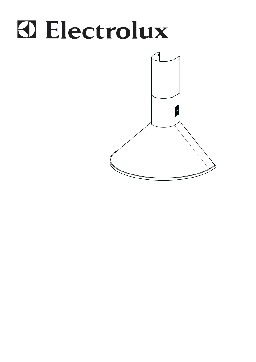
EFC 90505
Page 2

EN
Instructions Manual
INDEX
RECOMMENDATIONS AND SUGGESTIONS......................................................................................................................5
CHARACTERISTICS..............................................................................................................................................................6
INSTALLATION ......................................................................................................................................................................8
USE.......................................................................................................................................................................................11
MAINTENANCE....................................................................................................................................................................12
2
2
Page 3

ES
Manual de instrucciones
ÍNDICE
CONSEJOS Y SUGERENCIAS ...........................................................................................................................................13
CARACTERÍSTICAS............................................................................................................................................................14
INSTALACIÓN......................................................................................................................................................................16
USO......................................................................................................................................................................................19
MANTENIMIENTO................................................................................................................................................................20
3
3
Page 4

PT
Manual de Instruções
ÍNDICE
CONSELHOS E SUGESTÕES............................................................................................................................................21
CARACTERÍSTICAS............................................................................................................................................................22
INSTALAÇÃO.......................................................................................................................................................................24
UTILIZAÇÃO.........................................................................................................................................................................27
MANUTENÇÃO....................................................................................................................................................................28
4
4
Page 5
EN
RECOMMENDATIONS AND SUGGESTIONS
INSTALLATION
• The manufacturer will not be held liable for any damages resulting
from incorrect or improper installation.
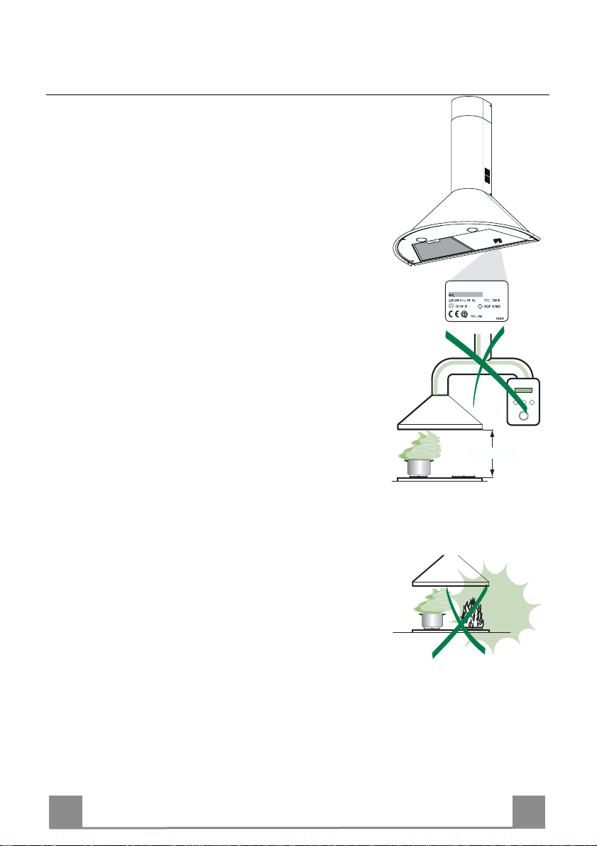
• The minimum safety distance between the cooker top and the extrac tor hood is 650 mm.
• Check that the mains voltage corresponds to that indicated on the
rating plate fixed to the inside of the hood.
• For Class I applianc es, c heck t hat th e domes tic po wer suppl y gua rantees adequate earthing.
Connect the extractor to the ex haust flue through a pi pe of minimum
diameter 120 mm. The route of the flue must be as short as possible.
• Do not connect the extractor hood to exhaust ducts carryi ng combustion fumes (boilers, fireplaces, etc.).
• If the extractor is used in conj unction with non-electrical appliances
(e.g. gas burning appliances), a suffici ent degree of aeration must be
guaranteed in the room in order to prevent the backflow of exhaust
gas. The kitchen must have an opening communicating directl y with
the open air in order to guarantee the entry of clean air.
USE
• The extractor hood has been designe d ex cl usi vely for domesti c us e to
eliminate kitchen smells.
• Never use the hood for purposes ot her than for which it has ben designed.
• Never leave high naked flames under the hood when it is in operation.
• Adjust the flame intensity to direct it onto the bottom of the pan only,
making sure that it does not engulf the sides.
• Deep fat fryers must be continuously monitored during use: overheated oil can burst into flames.
• The hood should not be used by chil dren or persons not inst ructed in
its correct use.
MAINTENANCE
• Switch off or unplug the appliance from the mains supply before carrying out any maintenance work.
• Clean and/or replace the Filters after the specified time period.
• Clean the hood using a damp cloth and a neutral liquid detergent.
650 mm min.
5
5
Page 6

EN
CHARACTERISTICS
Dimensions
270
MIN.400 - MAX.660
6
6
Page 7

EN
Components
Ref. Q.ty Product Components
1 1 Hood Body, complete with: Controls, Light,
Blower, Filter s
2 1 Telescopic Chimney comprising:
2.1 1 Upper Section
2.2 1 Lower Section
9 1 Reducer Flange ø 150-120 mm
14.1 2 Air Outlet C onnection Ex tension
15 1 Air Outlet C onnection
Ref. Q.ty Installation Components
7.1 1 Hood Body Fixing Bracket
7.2.1 2 Upper Chimney Section Fixing Brackets
11 6 Wall Plugs
12a 6 Screws 4,2 x 44,4
12c 6 Screws 2,9 x 9,5
Q.ty Documentation
1 Instruction Manual
15
14.1
9
1
12c
12a 11
12c
7.2.1
7.1
7
7
Page 8

EN
INSTALLATION
Wall drilling and bracket fixing
7.2.1
650 min.
Wall marking:
• Draw a vertical line on the supporting wall up to the ceiling, or as high as practical, at the
centre of the area in which the hood will be installed.
• Draw a horizontal line at 650 mm above the hob for installation without the back panel, or at
height H (H = height of the visible part of the panel) for installation with the back panel.
• Place bracket 7.1 on the wall as shown, 287 mm above the horizontal reference line, align-
ing the centre (notch) with the vertical reference line.
• Mark t he wall at the centres of the holes in the bracket.
• Place bracket 7.2.1 on the wall as shown about 1-2 mm from the ceiling or upper limit align-
ing the centre (notch) with the vertical reference line.
• Mark t he wall at the centres of the holes in the bracket.
• Place bracket 7.2.1 on the wall as shown at X mm below the first bracket (X = height of the
upper chimney section supplied), aligning the centre (notch) with the vertical line.
• Mark t he wall at the centres of the holes in the bracket.
1÷2
X
7.1
H 287
REAR PANEL (OPTIONAL)
The Rear Panel must be fitted before fixing the hood body and, for both upper an lower positiion fixing, must be fitted at the correct height prior to installing the bases. As this operation is
rather complex, it should be carried out either by the kitchen installer or a qualified person
who knows the final dimensions of the units.
For the upper fixing posi tion , proceed as follows:
• Rest the back pan el on the base, in serting th e lower plat e between the u pper surface an d the
wall, centring it on the vertical reference line.
• Mark the centres of the two holes in the upper plate.
• Drill ø 8 mm holes at all the centre points marked.
• Insert the wall plugs 11 in the holes.
• Fi x the brackets using the 12a screws (4,2 x 44,4) supplied.
• Fix the back panel (where present) using the 12a (4,2 x 44,4) screws supplied.
8
8
Page 9

EN
Mounting the hood body
• Before hooking up the hood body, adjust the two screws Vr
located on the hood body connection points so that they are at
the half way point.
• Hook the hood body to the mounted bracket.
• Adjust the screws Vr to level the hood body.
• Tighten the lock screw Vf.
Connections
DUCTED VERSION AIR EXHAUST SYSTEM
When installing the ducted version, connect the hood to the
chimney using either a flexible or rigid pipe ø 150 or 120 mm,
the choice of which is left to the installer.
• To install a ø 120 mm air exhaust connection, insert the reducer flange 9 on the hood body outlet.
• Fix the pipe in position using sufficient pipe clamps (not supplied).
• Remove any activated charcoal filters.
Vf
Vr
ø 120ø 150
9
RECIRCULATION VERSION AIR OUTLET
• Push fit connection 15 onto the hood body outlet.
• Insert the con nection extensio n pieces laterall y 14.1 in conn ection 15.
• Make sure that the outlet of the extension pieces 14.1 is horizontally and vertically aligned with the chimney outlets. If this
is not the case, adjust the position by either reversing the connection extension pi eces 14.1 and then reasse mble as d escrib ed
previously.
• Ensure that the activated charcoal filters have been inserted.
14.1
15
9
9
Page 10

EN 110
ELECTRICAL CONNECTION
• Connect the hood to the mains through a two-pole switch having a contact gap of at least 3 mm.
• Re move the grease filters (see paragraph Maintenance) being
sure that the conn ector of the feeding cable is correctly inserted
in the socket placed on th e side of the fan.
Flue assembly
7.2.1
12c
Upper exhaust flue
• Slightly widen the two sides of the upper flue and hook them
behind the brackets 7.2.1, making sure that they are well
seated.
• Secure the sides to the br ackets using the 4 screws 12c (2,9 x
9,5) supplied.
Lower ex haust flue
• Slightly widen the two sides of the flue and hook them between the upper flue and the wall, making sure that they are
well seated.
• Fix the lower part laterally to the hood body using the 2 screws
1
12c
12c (2,9 x 9,5) supplied.
Page 11

EN 111
USE
3
2
1
1
0
1
0
V
M
L
L Light Switches the lighting system on and off
M Motor Switches the extractor motor on and off
V Speed Sets the operating speed of the extractor:
1. Low speed, used for a co ntinu ous and silent air ch ange i n the presen ce o f
light cooking vapour.
2. Medium speed, suitable for most operating conditions given the optimum
treated air flow/noise level ratio.
3. Maximum speed, used for eliminating the highest cooking vapour emission, including long periods.
Page 12

EN 112
MAINTENANCE
Grease filters
CLEANING META L SELF- SUPPORTING GREASE FILTERS
• The filters must be cleaned every 2 months of operation, or
more frequently for particularly heav y usage, and can be
washed in a dishwasher.
• Remove the filters one at a time by pushing them towards
the back of the group and pulling down at the same time.
• Wash the filters, taking care not to bend th em. Allow them
to dry before refitting.
• When refitting the filters, make sure that the handle is visible
on the outside.
Activated charcoal filter (Recirculation version)
These filters are not washable and cannot be regenerated, and
must be replaced approximatel y every 4 months of operati on, or
more frequently with heavy usage.
REPLACING THE ACTIVATED CHARCOAL FILTE R
• Remove the metal grease filters
• Remove the saturated activated charcoal filter as shown (A).
• Fit the new filters (B).
• Replace the metal grease filters.
B
A
Lighting
LIGHT REPLACEMENT
40 W incandescent light.
• Remove the metal grease filters.
• Unscrew the bulb s and replace th em with new on es having the
same characteristics.
• Replace the metal grease filters.
Page 13

Page 14

Page 15

Page 16

The symbol on th e product or on its packaging indicates that this produc t m ay n ot be treated as household waste. Instead it shall
be handed over to the appl icable col lection p oint for t he recycli ng of electr ical and el ectronic equipment . By ensurin g this product is
disposed of correctly, you will help prevent potential negative consequences for the environment and human health, which could otherwise be caused by inap propr iat e wast e ha ndl ing of this pro duc t. For mor e det ail ed inf ormati o n about recy cli ng of this pro duc t, ple ase
contact your local city office, your household waste disposal service or the shop where you purchased the product.
El símbolo en el produc to o en su embalaje ind i c a q ue este producto no s e puede tratar como desperdicios normales del hogar.
Este product o se de be entre g ar al p unt o de r ec olec ci ón d e equi pos el éctri cos y el ectr óni cos p ar a reci cl aje. A l as eg urars e d e qu e est e
producto se des eche c orrec tame nte, us ted ay udar á a evi tar posi bles c onsec uenci as neg ativas par a el ambi ente y l a salu d públ ica, lo
cual podría oc urrir si este pr oduct o no se mani pula de form a adec uada. P ara obte ner inf orma ción más detall ada so bre el r ecicl aje de
este product o, pó ngas e e n c ontac to c on l a a dm ini str ación d e su ci ud ad, c on s u s ervi ci o de desec hos del hog ar o co n la tien da d onde
compró el producto.
O símbolo no produto ou na em b al a gem indica que este produ to n ão pode ser tratado com o l i x o d om és ti co. Em vez disso, deve
ser entregu e ao centro de recolha sel ectiva para a reciclag em de equip amento eléctr ico e elec trónico. Ao garantir uma eliminação
adequada deste produto, irá ajud ar a ev i t ar eventuais consequê nci as negativas para o meio ambiente e para a sa úde pública, que, de
outra forma, p oderiam ser provocadas p or um tratamento incorrecto d o produto. Para obter inf o r m aç õ es m ai s p or m en or i zadas sobre a
reciclagem des te pro duto, con tacte os s erviços munici palizados locai s, o centr o de recol ha sel ectiva da s ua área de r esidê ncia ou o
estabelecimento onde adquiriu o produto.
436003244_ver1
 Loading...