

Page 1
Gebrauchsanweisung , Notice d'utilisation et d'installation
EFC 6450
Installatie- en gebruiksaanwijzing , User manual
D
F
NL
UK
Page 2

Contents
Safety warnings 27
for the installer 27
for the user 27
Description of the appliance 2 8
Extractor version 28
Filter V ersion 28
Control Panel 2 9
Correct ventilation 29
If the hood does not function 2 9
Before you make contact to service 29
Service and spare parts 29
Maintenance and care 3 0
Cleaning 30
Metal grease filter 30
Open the metal grease filter 30
Warning 30
Charcoal filter 31
Changing the light bulb 31
Technical Specifications 3 1
Special accessories 31
Installation 32
Unpacking 32
Placement 32
Electrical connection 32
Mounting accessories included 33
W all unit mounting 33
UK
Before you use the cooker hood we recommend that you read through the whole user manual giving a direct
description of the cooker hood and its functions.
T o avoid the risks, that are always present when you use a product driven by electricity, it is important that the
cooker hood is installed correctly and that you read the safety instructions carefully to avoid misuse and hazard.
Save the instruction manual and keep it available at use of the cooker hood
26
Page 3
Safety warnings
for the installer
• When used as an extractor unit, the hood must
be fitted with a 150mm diameter hose.
Should there already be a pipe of diameter 125
mm that ducts to the outside through the walls
or roof, it is possible to use the 150/125 mm
reduction flange provided. In this case the hood
will be slightly more noisy .
• When installing the hood, make sure you
respect the following minimum distance
from the top edge of the cooking hob/ring
surfaces:
electric cookers 500 mm
gas cookers 650 mm
coal and oil cookers 750 mm min.
• The national standard on fuel-burning systems
specifies a maximum depression of 0.04 bar in
such rooms.
• The air outlet must not be connected to chimney
flues or combustion gas ducts. The air outlet
must under no circumstances be connected to
ventilation ducts for rooms in which fuel-burning
appliances are installed.
• It is advisable to apply for authorization from the
relevant controlling authority when connecting
the outlet to an unused chimney flue or
combustion gas duct.
The air outlet installation must comply with the
regulations laid down by the relevant authorities.
• When the unit is used in its extractor version, a
sufficiently large ventilation hole must be
provided, with dimensions that are
approximately the same as the outlet hole.
• National and regional building regulations
impose a number of restrictions on using hoods
and fuel-burning appliances connected to a
chimney , such as coal or oil room-heaters and
gas fires, in the same room.
• Hoods can only be used safely with appliances
connected to a chimney if the room and/or flat
(air/environment combination) is ventilated from
outside using a suitable ventilation hole approximately 500-600 cm
possibility of a depression being created during
operation of the hood.
• If you have any doubts, contact the relevant
controlling authority or building inspector’s
office.
• Since the rule for rooms with fuel burning
appliances is “outlet hole of the same size as the
ventilation hole”, a hole of 500-600 cm2, which
2
large to avoid the
is to say a larger hole, could reduce the performance of the extractor hood.
• If the hood is used in its filtering function, it will
operate simply and safely in the above
conditions without the need for any of the
aforementioned measures.
• When the hood is used in its extractor function,
the following rules must be followed to obtain
optimal operation:
— short and straight outlet hose
— keep bends in outlet hose to a minimum
— never install the hoses with an acute angle,
they must always follow a gentle curve only
— keep the hose as large as possible
(preferably the same diameter as the outlet
hole).
• Failure to observe these basic instructions will
drastically reduce the performance and increase
the noise levels of the extractor hood.
for the user
• Always cover lighted elements, to prevent
excess heat from damaging the appliance. In
the case of oil, gas and coal fired cookers it is
essential to avoid open flames.
• Also, when frying, keep the deep frying pan on
the cooker top/cooker under careful control.
• The hot oil in the frying pan might ignite due to
overheating.
• The risk of self-ignition increases when the oil
being used is dirty .
• It is extremely important to note that
overheating can cause a fire.
• Never carry out any flambé cooking under
the hood.
• Always disconnect the unit from the power
supply before carrying out any work on the
hood, including replacing the light bulb
(take the cartridge fuse out of the fuse holder or
switch off the automatic circuit breaker).
• It is very important to clean the hood and
replace the filter at the recommended
intervals. Failure to do so could cause
grease deposits to build up, resulting in a
fire hazard.
27
Page 4
Description of the appliance
Extractor version
• The hood is supplied as an extractor unit and
can also be used with a filtering function by
fitting one charcoal filter (special accessory).
• Y ou will need original ELECTROLUX charcoal
filter for this function (see Special Accessories).
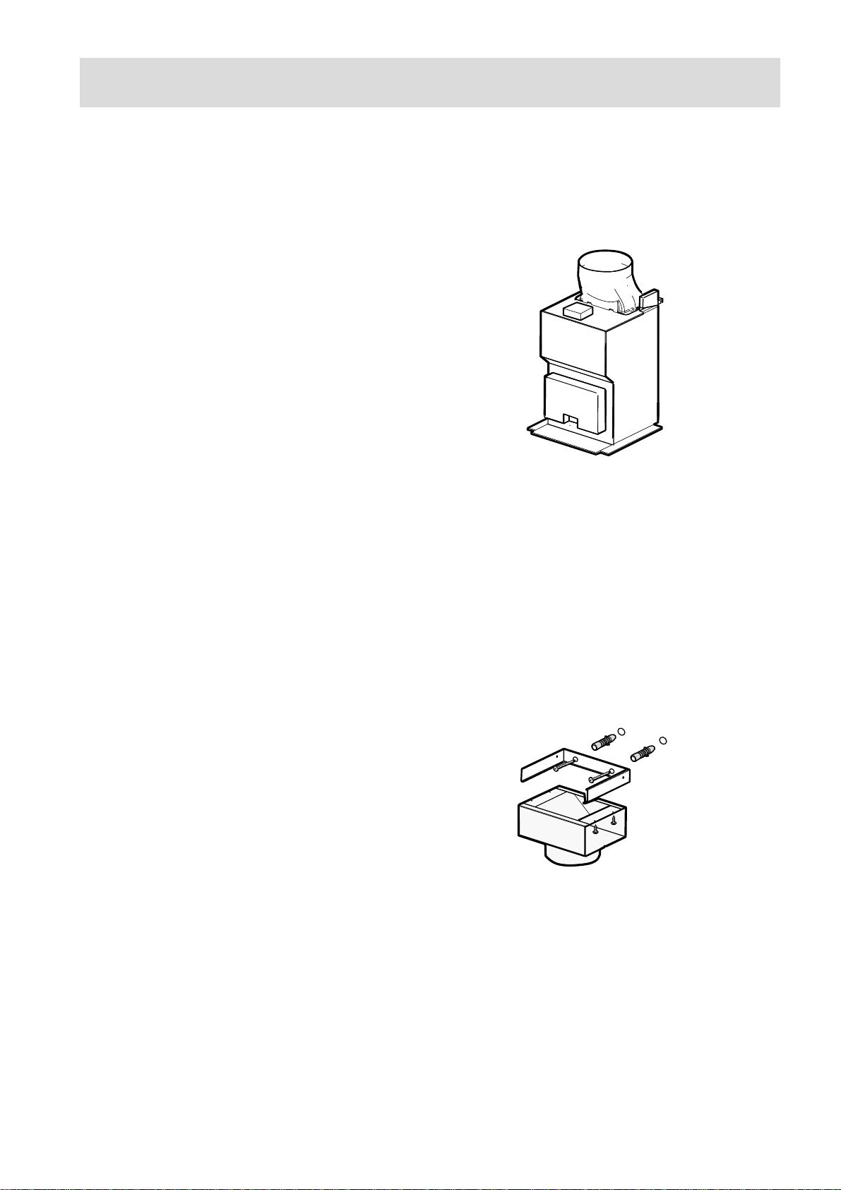
• The air is discharged to the outside through a
pipe, which must be fitted to connection flange
D. Fig. 1.
• In order to obtain the best performance the hose
should have a diameter equal to the outlet hole.
Should there already be a pipe of diameter 125
mm that ducts to the outside through the walls
or roof, it is possible to use the 150/125 mm
reduction flange provided. In this case the hood
will be slightly more noisier.
D
Fig. 1
Filter Version
• The air is filtered through a charcoal filter and
returned to the kitchen through the top grill of
the outlet pipe.
• Y ou will need an original ELECTROLUX KF20
charcoal filter for the filtering function. (See
Special Accessories).
• Fix the deflector using 4screws Ø2,9x6,5mm .
Fig. 2.
Fig. 2
28
Page 5

Control Panel
• The hood is fitted with one motor having several
speed. Turn the hood on a few minutes before
you start cooking, you will then get an under
pressure in the kitchen. The hood should be left
on after cooking for about 15 minutes or until all
the odours have disappeared.
The control switches are located on the unit’s
front panel:
• the light switch switches the hood lamp on and
off;
• Light switch: this switch is used to turn the
light fitted in the hood on and off.
• Extractor fan switch/Push-button 1: used to
turn the fan off and to set the fan to speed 1.
• Push-button 2: used to set the fan to speed 2.
• Push-button 3: used to set the fan to speed 3.
Correct ventilation
Lamp indicator
Extractor fan
Push-button
Light switch
Fig. 3
switch/
1
Push-button
Push-button
3
2
If the cooker hood is to work correctly there must
be an under pressure in the kitchen. It is important
to keep the kitchen windows closed and have a
window in an adjacent room open.
If the hood does not function
Before you make contact to
service
Check that the power plug is connected to the wall
power outlet and that no fuse is blown. Do not do
any operations that can cause hazard or damage to
the product. If the problem remains contact your
dealer or an approved service company
denomination. This information you will find on the
rating label.
Take away the grease filter and you will find the
rating label behind.
Model:_________________________________
Product number: ________________________
Remember to save the purchase recite and the
Warranty card (only used in some countries)
Service and spare parts
Service and spare parts you will get via your dealer
or service company.
When you order service or spare parts you should
be ready to give the product number and model
Date of purchase: ________________________
29
Page 6

Maintenance and care
The hood must always be disconnected from the electricity supply before beginning any
maintenance work.
Cleaning
• W arning: always disconnect the hood from the
mains power supply before cleaning it.
Never insert pointed objects in the motor’s
protective grid.
• Wash the outside surfaces using a delicate
detergent solution. Never use caustic detergents
or abrasive brushes or powders.
• Only ever clean the switch panel and filter grille
using a damp cloth and delicate detergents.
• It is extremely important to clean the unit and
change the filters at the recommended intervals.
Failure to do so will cause grease deposits to
build up that could constitute a fire hazard.
Metal grease filter
• The purpose of the grease filters is to aspirate
grease particles which form during cooking and
it must always be used, either in the external
evacuation or internal recycling function.
Attention: the metal grease filters must be
removed and washed, either by hand or in the
dishwasher, every four weeks.
Warning
• Failure to observe the instructions on cleaning
the unit and changing the filters will cause a fire
hazard. You are therefore strongly
recommended to follow these instructions.
• The manufacturer declines all responsibility for
any damage to the motor or any fire damage
linked to inappropriate maintenance or failure to
observe the above safety recommendations.
Open the metal grease filter
• Pull out the spring-lock to release the grease
filter. Fig. 4.
Hand washing
Soak grease filters for about one hour in hot
water with a grease-loosening cleaner, then
rinse off thoroughly with hot water. Repeat the
process if necessary. Refit the grease filters
when they are dry.
Dishwasher machine
Place grease filters in dish washer. Select most
powerful washing programme and highest
temperature, at least 65°C. Repeat the process.
Refit the grease filters when they are dry.
When washing the metal grease filter in the
dishwasher a slight discoloration of the filter can
occur, this does not have any impact on its
performance.
• Clean the inner housing using a hot detergent
solution only (never use caustic detergents,
abrasive powders or brushes).
Fig. 4
30
Page 7

Charcoal filter
• The charcoal filter should only be used if you
want to use the hood in its filtering function.
• T o do this you will need an original
ELECTROLUX charcoal filter (see special
accessories).
• Cleaning/replacing the carbon filter
Unlike other carbon filters, the LONGLIFE
charcoal filter can be cleaned and reactivated.
At normal use the filter should be cleaned every
second month. The best way to clean the filter
is in the dishwasher. Use normal detergent and
choose the highest temperature (65º C). Wash
the filter separately so that no food parts gets
stuck on the filter and later causes bad odours.
T o reactivate the charcoal, the filter should be
dried in an oven for 10 minutes with a temperature of maximum 100º C.
After approximately three years of use, the
carbon filter should be replaced with a new, as
the odour reduction capacity will be reduced.
• Mounting
Remove the frame i which supports the filter h
by turning 90° the two knobs g, Fig.5. Insert
the charcoal mattress inside the frame and put
all parts back in their place.
• To dismount proceed in reverse order.
• Always specify the hood model code number
and serial number when ordering replacement
filters. This information is shown on the
registration plate located on the inside of the
unit.
• The charcoal filter can be ordered from the
ELECTROLUX technical assistance service.
h
i
g
g
g
g
h
Fig. 5
Changing the light bulb - Fig. 6
• Disconnect the cooker hood from the main
supply .
• Remove the lamp cover, use a screw driver as a
lever.
• Replace the old bulb with a new one of the
same type.
• Remount the lamp cover.
• If the light does not come on, make sure the
bulb has been inserted in correctly before
contacting the technical assistance service.
Fig. 6
31
Page 8

Technical Specifications
Dimensions (cm) Height 86 - 115
Width 89,9
Depth 50
Lighting 2 x 20 W
Grease filter 1
power absorption 210 W
We reserve the right to generate constructive and chromatic modifications as required by technological growth.
Special accessories
Carbon filter KF 20 E-Nr . 942 120 600
Installation
Unpacking
Check that the cooker hood has no damages.
Transportation damages should immediately be
reported to the one responsible for the transport
Damages, faults and eventually missing details
should immediately be reported to the seller.
Take care of the packing material so that small
children cannot play with it.
Placement
The hood is to be mounted on the wall.
When installed, the hood must be not less than
50cm. above electric burners or 65 cm. above gas
or mixed-fuel burners (fig. 7).
Electrical connection
Safety warnings for the electrician
Before connecting the appliance to the power
supply , check that the voltage indicated on the
rating plate corresponds to the mains power supply
available. Appliances fitted with a plug can be
connected to any standard power socket within
easy access.
Should it be necessary to provide a fixed
connection, the hood must only be installed by an
electrician authorised by the local electricity board.
When installing, an omnipolar disconnector with a
distance of at least 3 mm between contacts must
be provided.
Min
50 cm
Min
65 cm
Fig. 7
This disconnector may be for example a switch,
fuses (plug fuses must be removed from the fuse
box, fault current switches and remote switches
with a distance of over 3 mm between contacts.
The manufacture declines all responsibility for
malfunctions resulting from failure to comply with
the above instructions.
If the power socket is applied directly above the
hood this gives two advantages:
1. the socket is not visible.
2. the appliance can be disconnected at need
merely be removing the plug.
Electrical connection
230 V – by means of fixed power cable with plug.
(Fixed connection of the appliance must only be
carried out by an authorised electrician.)
32
Page 9

Installation
Mounting accessories included
1 deflector, 1 chimney support, 1 reduction flange Ø 125-120 mm, 1 support bracket, 5 wood-screws 5 x 45 mm,
5 wall plugs Ø 8 mm, 6 metal screws 2,9 x 6,5, 10 metal screws 3 x 9
Wall unit mounting - Fig. 8
Disconnect the hood during electrical
connection, by turning the home
mains switch off.
• Sign the wall with a center line,
this will aid mounting procedure
F
(1), position the template so that
the mid line printed on the
template matches with the center
line previously signed, the lower
5
side of the template corresponds
to the lower side of the hood once
mounted (2).
• Drill two holes Ø 8mm and fix the
support bracket with two wall
plugs and screws (3).
• Hang the hood (4) and thread the
lower part of the hood onto it (5).
5
5
• Make all the electrical connections
between the two parts (6).
• Fasten the hood to the suction unit
using 10 screws (7).
• Adjust the position (8-9) and from
the inside of the hood sign one
point for definitive fixing (10),
remove the hood (11) and drill an
6
hole Ø 8mm (12), fit a wall plugs
(13).
• Drill two holes Ø 8mm on the
upper side close to the ceilling
(14), fit two wall plugs and fix the
chimney support with two screws
(15).
• Hang the hood again (16).
• Fix it definitively with a screw
(17). T o simplify the mounting
operation remove the carbon filter frame.
• In case the hood is to be used in filter version, mount the deflector F on the chimney support G with four
screws 2,9x6,5 and fit an exhausting pipe (18) to connect deflector to the outlet hole D of the hood.
In case the hood is to be used in exhausting version, then the deflector must not be mounted and fit an
exhausting pipe (18) to connect outlet hole D of the hood to the outside.
• Make electrical connection (13), but leave the hood disconnected from the home general electric panel.
• Fix the chimney (16a) to the chimney support (16b).
Slide down the lower section on the proper housing on top of the hood. Connect the hood the the home general
electric panel and check if the hood work properly .
5
20a
19
Fig. 8
20a
H
20b
14
14
G
15
4-16
11
18
9
8
9
17
5
9
D
8
8
13
7
7
4-16
12
20b
1
11
3
2
10
7
7
33
Page 10

34
Page 11

35
Page 12

LI1X9A Ed.04/02
 Loading...