

Page 1
Instructions Manual
Kullanim Kilavuku
EFC 60110
Page 2

EN
Instructions Manual
INDEX
WARNINGS - COMPONENTS...............................................................................................................................................4
INSTALLATION ......................................................................................................................................................................5
USE - MAINTENANCE...........................................................................................................................................................6
2
2
Page 3

TR
Kullanim Kilavuku
IÇERIKLER
UYARILAR - PARÇALARI......................................................................................................................................................7
MONTAJ.................................................................................................................................................................................8
KULLANIM - BAKIMI VE TEMİZLENMESİ.............................................................................................................................9
3
3
Page 4
EN
WARNINGS - COMPONENTS
WARNINGS
This appliance has been design ed for use as eith er an EXTRACTION (ducting to the outside)
or RECIRCULATION (filtering) hood. The measurements contained on the drawings in this
booklet refer to two models of cooker hood. Therefore, it is essential that you refer to the correct drawing when taking measurements for installation.
- The minimum distance betw een the cooking surfac e and the metal g rease filters on the
underside of the hood must be 650mm.
- This cooker hood must be installed in accordance with the installation instructions and
all requirements must be adhered to.
- If the room where the coo ker h ood is to be us ed co ntai ns a fu el burni ng a pplian ce suc h
as a central heating boiler then its flue must be of the room sealed or balance flue type.
- If other ty pes of f l ue or a ppl ian ces are f it ted e ns ure t hat t here is an adequate su pply of
air to the room.
- When the cooker hood is used in conjunction with appliances supplied with energy
other than electricity, t he negative pressure i n the room must not ex ceed 0.4 mbar to
prevent fumes being drawn back into the room by the hood.
- The ducting system for this appliance must not be connected to any ve ntilation system
which is being used for any other purpose.
- The ducting system for this appli ance must not be connect ed t o any existing ventilation
system which is being used for any other purpose.
- Do not leave naked flames or carry out flambè cooking under this cooker hood.
CONNECTION TO THE MAINS WARNING: DOUBLE INSULATED DO NOT EARTH
Before connecting to the mains supply ensure the mains voltage corresponds to the voltage on
the rating plate inside the hood.
This appliance is fitted with a 2 core mains cable and must be permanently connected to the
electricity supply via a double-pole switch having 3mm minimum contact gap on each pole.
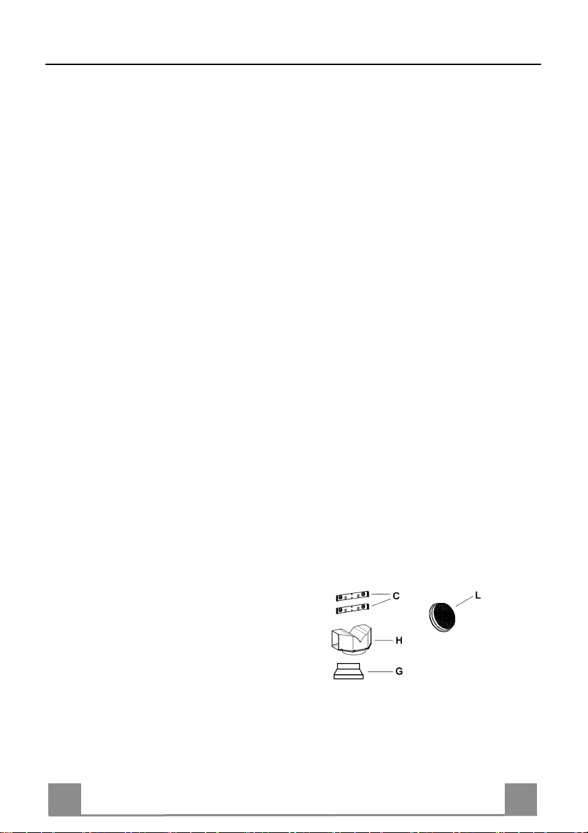
COMPONENTS
- 2 No Wall Brackets C
- 1 No 150-120mm Ducting Spigot G
- 1 No Air Outlet Connection H
- 2 No Charcoal F i lters L (Optional)
4
4
Page 5

EN
INSTALLATION
The cooker hood must be installed centrally over a cooking appliance. The minimum distance
between the cooking surface and the metal grease filters on the underside of the hood must be
at least 650mm.
To install the hood proceed as follows:
1) Drill six 8mm diameter holes at X1-X2-J and insert the plastic rawl plugs supplied as illus-
trated in fig. 2 ensuring the brackets are fitted as shown in the blow up.
2) Secure the two brackets C to the wall inserting two of the screws supplied through the two
holes on line X1-X2 as illustrated in fig. 2.
3) Slide the canopy down the wall to locate the key hole over the washer then secure the can-
opy to the wall by inserting two of the screws supplied through the two outer holes in the
rim of the canopy J1 and J2 as illustrated in fig. 3.
4) EXTRACTION OR RECIRCULATION INSTALLATION:
• EXTRACTION (DUCTED)
When installing the ducted version, connect the hood to the chimney using either a flexible or
rigid pipe ø 150 or 120 mm, the choice of which is left to the installer.
• To install a ø 120 mm air exhaust connection, insert the reducer flange 9 on the hood body
outlet.
• Fix the pipe in position using sufficient pipe clamps (not supplied).
• Remove any activated charcoal filters.
• RECIRCULATION (FILTERED)
• When the hood is fitted in the recirculation mode the Air Outlet Connection H should be
fitted as illustrated in fig. 6.
• Fit the (optional) charcoal filters by repeating the following operation on each side of the
motor housing. Place the two key hole slots in the filter L and turn the filter clockwise to
lock the filter in position as illustrated in fig. 7.
WARNING: It is a possible fire hazard if the metal grease filters are not cleaned and the
charcoal filters replaced regularly.
Fitting The Chimney
5) FITTING THE CHIMNEY UPPER
To fit the upper chimney A, place the top edge of the ch imney o ver th e bracket C as illus-
trated in fig. 8 and secure the chimney using two of the 2.9mm self tapping screws provided.
The distance H in the height between the fixing holes X1 and X2 is determined by the
height of the upper chimney A.
6) F ITTI N G TH E CH IM N E Y LO W ER
To fit the lower chimney B, apply slight force to the two rear edges to in crease the widt h
of the apperture, then sleeve the chimney B over the chimney A as illustrated in fig. 9.
5
5
Page 6

EN
USE - MAINTENANCE
USE
The cooker hood functions are controlled by a series of slider or push button switches mounted
on the front of the hood and control the worktop lighting and fan motor speeds. This cooker
hood will not remove steam.
1) SLIDER SWITCHES
- A switch controls the wotktop lighting - ON/OFF.
- A switch controls the fan speeds - OFF/ON-1-2-3.
- The red neon lamp illuminates when the motor is switched ON .
2) PUSH BUTTON SWITCHES
- A switch controls the worktop lighting - ON/OFF.
- A button switches the motor OFF/ON at the low speed setting.
- A button switches the motor to the medium speed setting.
- A button switches the motor to the high speed setting.
- The red neon lamp illuminates when the motor is switched ON.
3) SPEED SETTINGS
- 1/Low should be selected when simmering or when using only one pan.
- 2/Medium should be selected for cooking when using up to four pans.
- 3/High should be selected when frying or cooking food with a strong odour.
MAINTENANCE
N.B. Before carring out any kind of maintenance, cleaning or replacing lamps, disconnect the
hood from the mains supply.
1. Lighting
Comprises two 40W bulbs. To repl ace the bu lbs, pro ceed as follo ws (fig.10 ): Remove on e
of the pins at the sides of the lamp co ver. Slide the glass to wards the side from which the
pin has been remo ved until the opposite edge has been freed, then pull gently downwards.
Replace the bults and fit the glass again by repeating the above operations in reverse order.
2. Filters
- The metal grease filter should be cleaned every two months or more frequently if the hood
is used consistently and can be cleaned in a dishwasher or by hand using a mild detergent
or liquid soap. When replacing, ensure that they are dry.
- The charcoal filter cannot be washed and should be replaced at least every 2 months or
more frequently if the hood is used consistently.
3. Cleaning
When cleaning the hood, it is recommended to use a damp cloth and mild liquid household
cleaner. Never use abrasive cleani ng materials.
IMPORTANT: When using a gas hob in connection with the cooker hood never leave the
burners of the hob uncovered while the hood is in use or when the pans have been removed. It is very important to follow all instructions for cleaning the hood and filters.
There could be a possible fire hazard if the filters are no t replaced according to these instructions.
ATTENTION: The manufacturer declines all responsibility for any damage or injury
caused as a result of not following the instructions for installation, for maintenance and replacement times of filters indicated (in order to avoid a possible risk of fire when the filters
are saturated with grease).
6
6
Page 7

TR
UYARILAR - PARÇALARI
UYARILAR
Bu cihaz ASPİRATÖRLÜ (havayı dışarı tahliye eden) yada FİLTRELİ (içerideki havayı
tekrar aktive eden) model davl umbaz olarak tasarlanmıştır.
- Tezgâh (setüstü ocak) ile davlumbazın alt kısmı arasındaki mesafe en az 650 mm olmalıdır.
- Davlumbazda havanın dışarı tahliye edildiği (aspiratörlü kullanım şekli) söz konusu
olduğunda aşağıdaki talimatlara uyunuz.
- Davlumbaz ile elektrik enerjisinden farklı bir ene rji ile çalışan cihazların aynı anda
çalışır duru mda oldukları mekânda iyi bir ha valandırma bul unmasına di kkat ediniz;
odanın negatif basıncı (vakumu) 4 atmosfer basıncını aşmamalıdır (4x10⁻⁵ bar).
- Mekânda toplanan hava, elektrik dışında bir enerji ile çalışan cihazlardan çıkan dumanları tahliye eden kanala-bacaya sevk edilmemelidir.
- Hava tahliyesi ile ilgili ol arak yerel yetki mercilerinin yönetmeliklerine uyunuz.
- Davlumbazın altındaki alanda serbest alev bulunmasına engel o lunuz.
- Davlumbaz Sınıf’II ye dahil izolasyona sahip olarak imal edilmiştir ve bu nedenle t oprak bağlantısı gerektirmez.
- Tüm bakım işl e mleri nden önce ciha zın elektri k bağlantısını kesiniz.
BESLEME KABLOSUNUN ŞEBEKEYE BAĞLANMASI
Montajdan önce cihaz üzerindeki etikette belirtilen şebeke voltajının evinizdeki voltaja uygun
olmasına dikkat ediniz. Kablo üzerine etikette belirtilen standartlarda bir fiş takılmalıdır; şebe-
keye direkt ba ğlantı yapılacaksa, cih az ile şebeke arasına temas aralığı en az 3 mm ol an çift
kutuplu bir elektr ik anahtarı konul malı, bu anahtar he m kaldıracağı yüke, hem de uluslararası
standartlara uygun olmalıdır.
PARÇALARI
- 2 adet tesbit braketi C
- 1 adet redüksiyon flanşı G
- 1 adet filtre rakoru H
- 2 adet aktif karbon filtresi L (isteğe bağlı)
7
7
Page 8

TR
MONTAJ
Davlumbaz setüstü ocağın tam merkezine monte edilmelidir. Setüstü ocak ile davlumbazın altı
arasındaki mesafe en az 650 mm olmalıdır.
Davlumbazın montajı için şu şekilde hareket ediniz:
1) Şekil 1’deki ölçülere uyarak 6 adet 8 mm çapında delik açınız (X1-X2-J).
2) Muhtelif parçaların montajlarında cihaz donanımındaki vidaları ve dübelleri kullanınız.
3) Braketleri C (şekil 2) duvardaki deliklere X1-X2 tesbit ediniz.
4) Davlumbazı duvardaki dış deliklere J1 ve J2 tesbit ediniz (şekil 3).
5) ASPİRATÖRLÜ yada FİLTRELİ modelin montajı:
• ASPIRATÖRLÜ
Aspiratörlü model montajında Davlumbazı çıkış borusuna seçimi montöre kalmış sert ya da
esnek 150 veya 120 mm çapında bir boru ile bağlayınız.
• 120 mm çapında boru ile bağlamak istiyorsanız Redüksiyon Flanşını 9 Davlumbaz Gövde-
si Çıkışına takınız.
• Boruyu uygun kelepçelerle tesbit ediniz. Bu malzeme donanımda verilmemiştir.
• Varsa Aktif Karbonlu Koku Filtrelerini çıkarınız.
• FİLTRELİ (OPSİYONEL MODEL)
- Filtre rakorunu H takınız (şekil 6).
- Aktif karbonlu filtreleri L (şekil 7) saat yönünde (yaklaşık 10° derece) döndürüp klik sesi
duyunca takıldıklarını anlayınız. Sökerken bu işlemleri tersine yapınız.
Baca Montajı
6) Üst bacayı A (şekil 8) braketlere C (şekil 2 / şekil 8) donanımdaki 4 adet 2,9 mm.lik vidayı
kullanarak sabitleyiniz. Tesbit vidaları arasındaki X1 - X2 mesafesi üst bacanın boyuna H
göre belirlenir.
7) Ön cepheden, yan taraflarını hafifçe açıp davlumbaza geçi rmek suretiyl e alt bacayı B (şe-
kil 9) monte ediniz (şekil 9).
8
8
Page 9

TR
KULLANIM - BAKIMI VE TEMİZLENMESİ
KULLANIM
Cihazı pişirme başlamadan kısa süre öncesinden çalıştırmanızı ve pişirme işlemi sona erdikten
sonra da koku tamamen giderilene kadar yaklaşık 15 dakika çalışır durumda bırakmanızı öneririz.
1) Elektrik düğmeleri bulunan kumanda paneli
- Bir adet aydınlatma düğmesi.
- Bir adet üç farklı çalışma hızı düğmesi.
- Motorun çalışmakta olduğunu gösteren uyarı lambası.
2) Butonlu kumanda paneli
- Motoru birinci hızda çalıştıran bir buton; son derece sessiz çalışarak hava dolaşımı sağla-
masıyla mutfakta az duman açığa çıkaran kullanım türüne uygundur.
- Motoru ikinci hızda çalıştıran bir buton; temizlediği hava miktarı ile çıkardığı gürültü ara-
sındaki oran mükemmel olduğundan en sık kullanım türlerine uygun çalışma şeklidir.
- Motoru üçüncü hızda çalıştıran bir buton; Uzun süreli ve çok dumanlı pişirme işlemlerinin
yapıldığı türden kullanımlara uygun çalışma şeklidir.
- Bir adet aydınl at ma butonu.
BAKIM
Not: Her türlü bakım, onarım ve ampul değiştirme işleminden önce, cih azla elektrik şebekesi
arasındaki bağlantıyı kesiniz.
1. Aydınlatma
Aydınlatmayı sağlayan iki adet 40 W ampuldür. Bunları değiştirirken şu şekilde hareket
ediniz (şekil 10):
Tavan lambasının kenarlarındaki iki adet pimden birini çıkarınız. Camı pimin çıkarılmış
olduğu tarafa kaydırınız ve karşı ucu kurtarıp aşağı doğru hafifçe çekiniz. Ampulleri değiş-
tiriniz ve işlemleri tersine yaparak camı takınız.
2. Filtreler
Davlumbazın kullanımıına göre sık ya da daha uzun aralıklarla, her halükârda ayda 2 kezi
geçirmemek suretiyle metalik filtreleri sökmek, sıcak su ve sabunla yıkamak gerekir. Bunları bulaşık makinasında da yıkamak mümkündür ve yerlerine takılmadan önce kurutulmaları lazımdır (aktif karbonlu filtreler kesinlikle yıkanmaz ve 2 ayda bir değiştirilirler).
3. Temizlik
Davlumbazın dış kısımlarının temizlenmesi için alkolle nemlendirilmiş bir bez ya da piya-
sada bulunan bu işe ait ürünler kullanılır. Aşındırıcı ve yıpratıcı ürünler kullanmayınız.
ÖNEMLİ: Serbest alev filtrelere zarar verir, bu yüzden ocakları üzerinde tencere olmadan
açık bırakmayınız. Filtrelerin ve davlumbazın bakımı, temizliği ve değişmesi gereken filtrelerin vaktinde değiştirilmeleri yangın riskini önlemek için ihmal edilmemelidir.
DİKKAT: Yağ filtrelerinin gerektiği gibi bakım gör memesi (i ki ayda bi r yıkama) , karbo n
filtrelerinin vaktinde değiştirilmemesi ve montaj ile elektrik bağlantılarının verilen talimatlara uygun olarak yapılmaması neticesinde gerçekleşecek olası hasar ve zararlar karşısında
üretici firma hiç bir sorumluluk üstlenmeyecektir.
9
9
Page 10

= =
= =
= =
180
A
B
180
180
750 min
1140 max
590 min
290
275
15
X1
H
X2
J
S30_01_n
600
700
900
X
X1
1
J
S30_02_n
C
J
H
X2
1
C
2
J
S30_03_n
2
2
1
3
G
4 5
Page 11

H
H
L
M
L
6
8
7
B
9
10
Page 12

The symbol on the product or o n i ts pac kaging indicates tha t thi s pr o d uc t m ay n ot b e tr e ated as household wast e. Instead it shall
be handed over to the appl icable col lection p oint for t he recycli ng of electr ical and el ectronic equipment . By ensurin g this product is
disposed of correctly, you will help prevent potential negative consequences for the environment and human health, which could otherwise be caused by inap propr iat e wast e ha ndl ing of this pro duc t. For mor e det ail ed inf ormati o n about recy cli ng of this pro duc t, ple ase
contact your local city office, your household waste disposal service or the shop where you purchased the product.
Ürün veya paketi üz erindeki sembolü, bu ürünün norm al bir evsel atık olar ak görülmemesi ve bu tip elektrikli veya elektronik
cihazların at ıldığı dönüşümlü toplama nokt aları na ter kedil mesi gerekti ğine işaret eder . Bu ür ünü gerek tiği gibi eli mine etm e kur allar ına
uyarsanız çevre ve insan sağlığı üzerindeki olumsuz etkilerini bert araf etmeye katkı s ağlamış olursunuz. Bu ür ünün geri dön üşüm
koşulları hakkında daha ayrıntılı bilgi için hudutları içinde bulunduğunuz belediyenin ilgili diaresine, atık yoketme servisine veya ürünün
satıcısına danışınız.
436003407_ver1
 Loading...