

Page 1
Installation
Instructions
Built-In Side-By-Side
Refrigerators
If you have questions, call 1-877-4ELECTROLUX 877-435-3287 or visit our website at:
BEFORE YOU BEGIN
Read these instructions completely
and carefully.
•
IMPORTANT — Observe all
governing codes and ordinances.
• Note to Installer – Be sure to leave these
instructions for the consumer’s and local
inspector’s use.
• Note to Consumer – Keep these instructions
with your Owner’s Manual for future reference.
• Skill Level – Installation of this refrigerator
requires basic mechanical, carpentry and
plumbing skills. Proper installation is the
responsibility of the installer. Product failure
due to improper installation is not covered
under the Electrolux Home Products
Warranty. See warranty information.
• Completion Time – 90 minutes (new
installations require more time than
replacement installations).
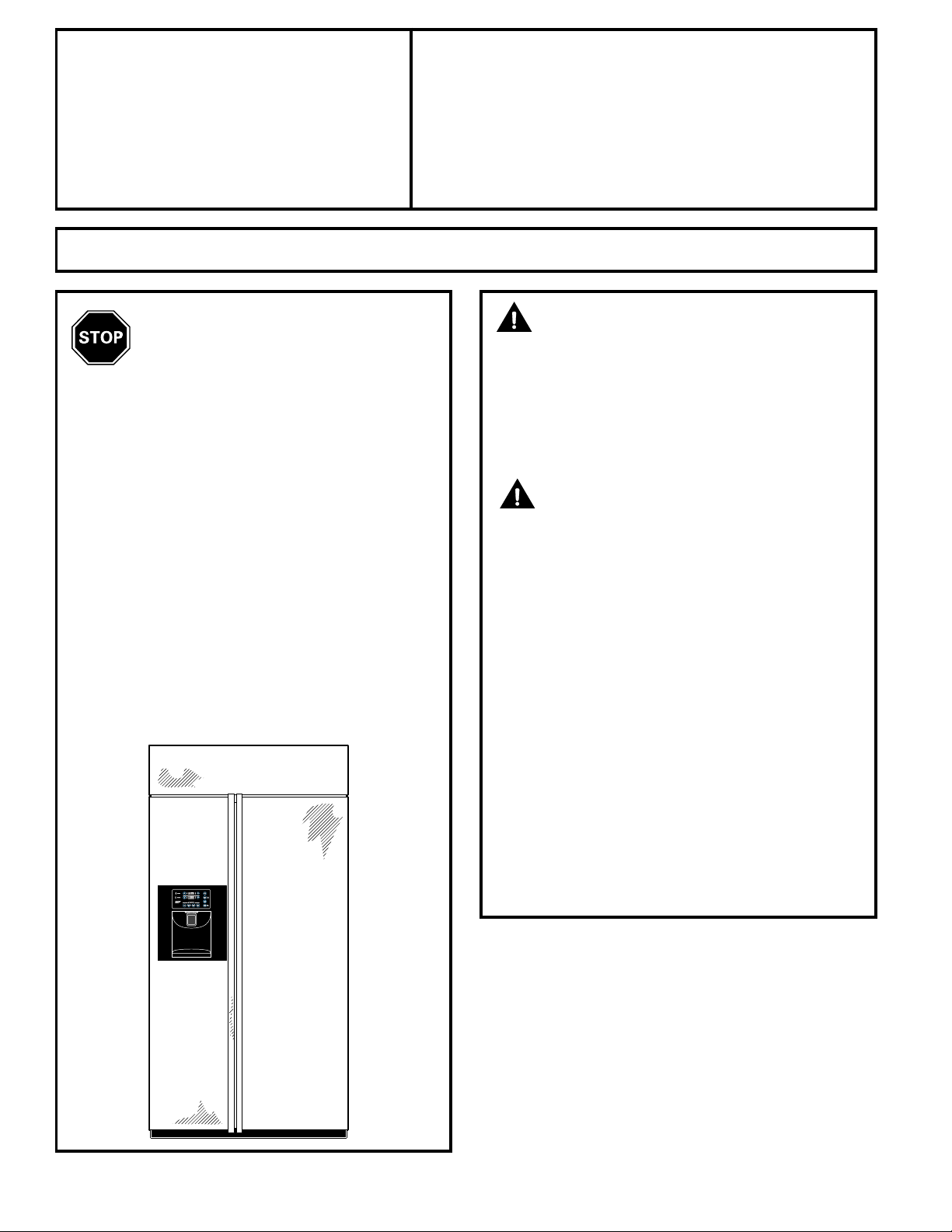
CAUTION:
Due to the weight and size of this refrigerator,
and to reduce the risk of personal injury or
damage to the product, A MINIMUM OF 4
PEOPLE ARE REQUIRED TO BRING THE UNIT
INTO THE HOME AND 2 PEOPLE ARE
REQUIRED FOR PROPER INSTALLATION.
WARNING:
• These refrigerators are top-heavy and must
be secured to prevent the possibility of
tipping forward. Anti-Tip protection is
required. See Step 4 on page 30 for details.
• Use this appliance only for its intended purpose.
• Immediately repair or replace electric power
supply cords that become frayed or damaged.
• Set the Master Power switch to the
O (OFF) position before cleaning or making
repairs.
• Repairs should be made by a qualified
service technician.
For local service in your area, call
1-877-4ELECTROLUX or 877-435-3287
For parts and accessories, call
1-877-4ELECTROLUX or 877-435-3287
READ CAREFULLY.
KEEP THESE INSTRUCTIONS.
15
Page 2
Installation Instructions
16
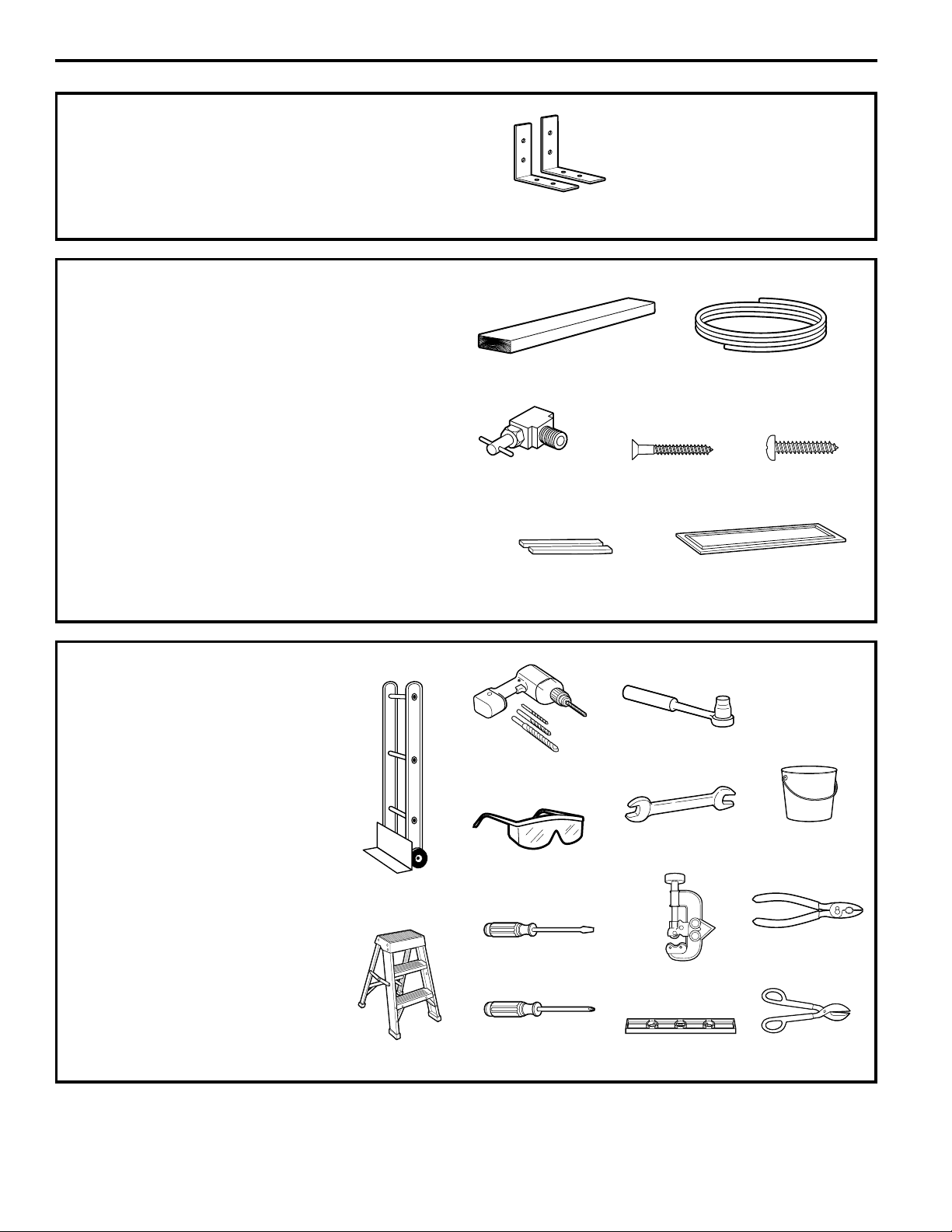
HARDWARE SUPPLIED
• Anti-Tip brackets
Anti-Tip Brackets
MATERIALS REQUIRED
• 36″ long, 2″ x 4″ wood block for Anti-Tip
bracket installation
• #12 or #14 wood screws for Anti-Tip bracket
• Screws to secure refrigerator to cabinets
• 1/4″ O.D. copper water line tubing.
• Water shutoff valve
• Custom panels for doors and grille panel
(if installing custom panels)
• Special 3M Dual Lock adhesive strips for
1/4″ side panels (if installing side panels)
36″ Wood Block 1/4″ O.D. Copper Water Line
Tubing
TOOLS REQUIRED
• Tinsnips to cut banding
• Stepladder
• Bucket
• Level
• Appliance dolly
• Tubing cutter
• Flathead screwdriver
• 1/2″ open-end wrench
• #2 Phillips screwdriver
• Drill and appropriate bits
• 7/32″, 1/2″ sockets
• Safety glasses
• 7/16″ open-end wrench
• Pliers
Appliance Dolly
Stepladder
Safety Glasses
Water Shutoff Valve #12 or #14
Wood Screws
Screws
Special 3M Dual Lock
Adhesive Strips
Custom Panels
Sockets
Open-end Wrenches Bucket
Drill & Bits
Flathead Screwdriver
Tubing Cutter
Phillips Head
Screwdriver
Level
Pliers
Tinsnips
Page 3
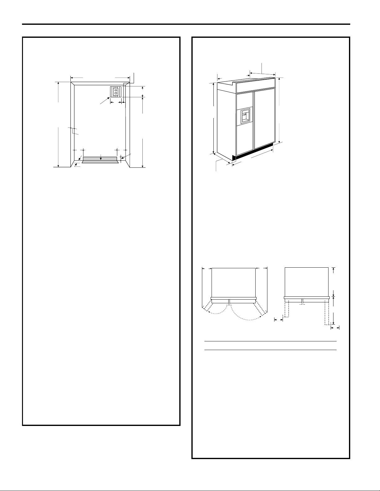
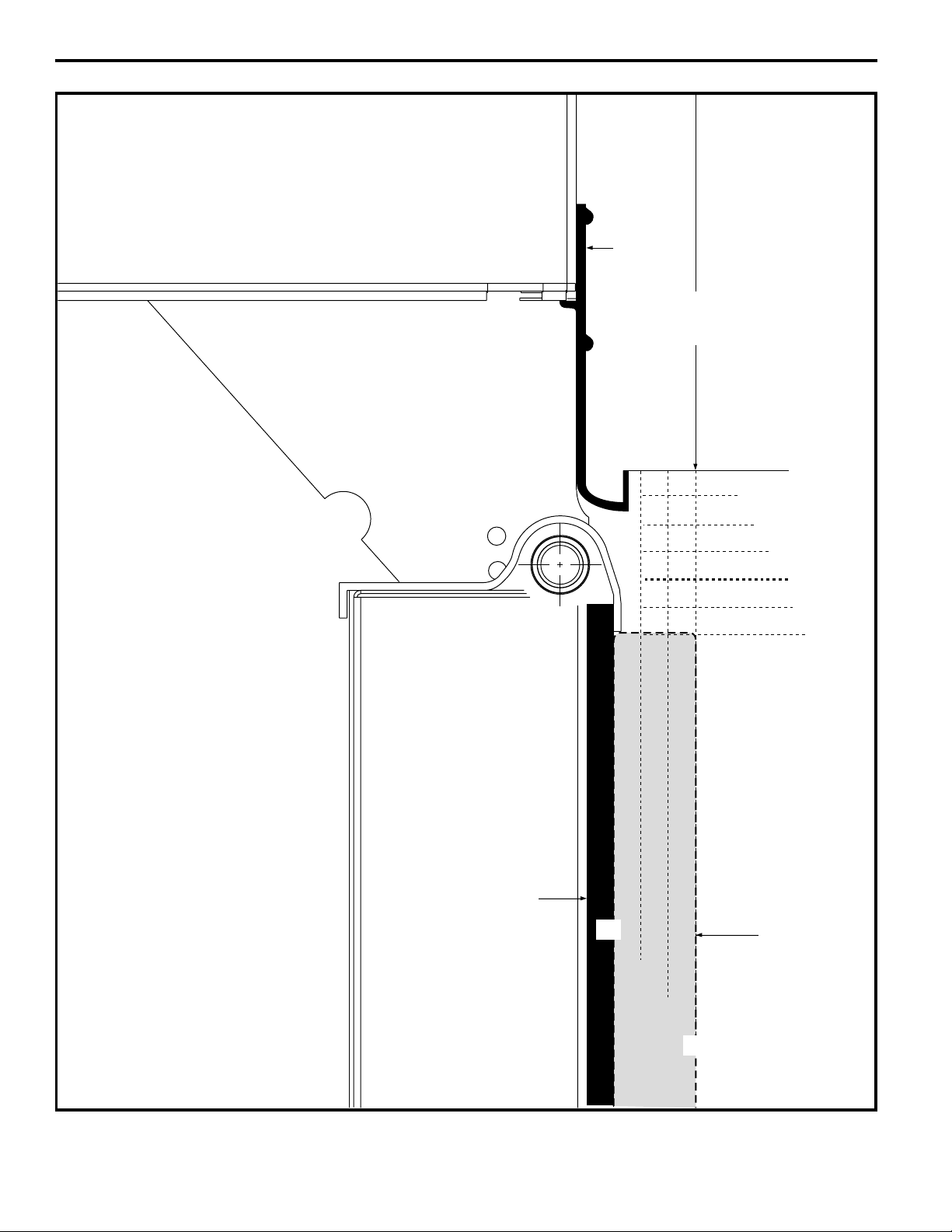
THE INSTALLATION SPACE
Water and Electrical Locations
The opening must be prepared with the
electrical and water supply located as shown.
The cutout depth must be 24″
The refrigerator will project forward, slightly
beyond adjacent cabinets, depending on
your installation.
Additional Specifications
• A 120 volt, 60Hz, 15 or 20 amp power
supply is required. An individual properly
grounded branch circuit or circuit breaker
is recommended. Install a properly
grounded 3-prong electrical receptacle
recessed into the back wall. Electrical must
be located on rear wall as shown.
Note: GFI (ground fault interrupter) is not
recommended.
• Water line can enter the opening through
the floor or rear wall. The water line
installed should be 1/4″ O.D. copper tubing
between the cold water line and water
connection location. The line should be
long enough to extend to the front of the
refrigerator. Installation of an easily
accessible shutoff valve in the water line is
required.
DIMENSIONS AND CLEARANCES
Allow minimum clearances for Freezer
door (Dimension A) and Fresh Food door
(Dimension B) for a full 130° door swing
and to allow for drawer removal.
Four inch (4″) minimum clearance is required
when door swing is adjusted to 90°. If the 90°
door stop position is used, drawer access is
maintained, but drawer removal is restricted.
See illustrations, pages 18 and 19, to
determine door swing interaction with
adjacent cabinets or countertops.
*The finished cutout width must be:
41-1/2″ for 42″ models
42" Frame-to-Frame
Depth Including
Handles 26-7/8"
41"
Case Width
25-3/8" Case Depth
*81-3/4"
at Rear
*84" From
Floor to
Top Frame
*Finished Width
Electrical
Area
84 1/2" max
83 1/2" min
Finished
Opening
74"
From Floor
to Bottom
of Electrical
24"
5"
5"
3 1/2"
Water Supply
3 1/2"
3"
7"
7"
Product Clearances
These refrigerators are equipped with a 2
position door stop. The factory set 130° door
swing can be adjusted to 90° if clearance to
adjacent cabinets or walls is restricted.
130° Door Swing 90° Door Swing
B
A
23-7/8"
Behind
Frame
C
D
D
Models A B C D
42″ 12-3/16″ 16″ 24″ 4″
Installation Instructions
*Shipping height
The front height
may be adjusted
from 83-1/2" to 84-1/2"
by adjusting front and
rear leveling legs a
maximum of 1".
17
Page 4
1/2"
1"
3/4" Custom Panel
(Nominal Size)
1/4"
1/2"
3/4"
2"
1-1/4"
1-1/2"
1-3/4"
3"
2-1/4"
2-1/2"
2-3/4"
1/4"
1/2"
3/4"
Fresh Food
Door
Backer Panel
23-7/8" From
Rear of
Refrigerator
1"
Refrigerator
Case
Trim
3/4"
1/4"
1"
Top View
130° Door Swing
(factory setting)
Scale 1:1
Installation Instructions
18
Page 5
1/2"
1/4"
1/2"
3/4"
1"
1-1/4"
1-1/2"
23-7/8"
From Rear of
Refrigerator
3/4" Custom Panel
(Nominal Size)
Case Trim
Refrigerator
Fresh Food
Door
Backer Panel
3/4"
1/4"
1"
Top View
90° Door Swing
(optional setting)
Scale 1:1
Installation Instructions
19
Page 6
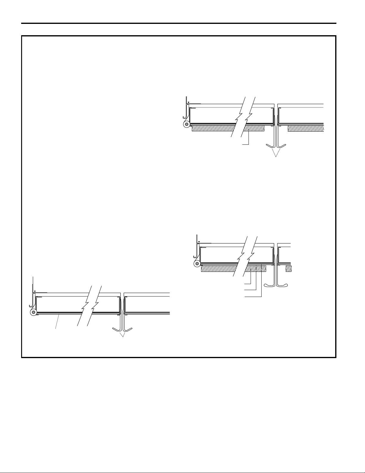
CUSTOMIZATION BASICS:
Stainless Steel Wrapped Models
Stainless Steel Wrapped Refrigerators
Stainless Steel wrapped refrigerators have
wrapped doors and grille panels, and beveled
edges. These models are shipped ready for
installation.
Trimmed Models
Trimmed Refrigerator Panels
Trimmed refrigerators are designed to be
customized with decorative panels. Field
installed custom door and grille panels are
required. There are three custom panel
options. You can install a 1/4″ framed panel,
a 3/4″ framed custom panel or a 3/4″ full-
width overlay custom panel.
1/4″ Framed Panels
You may install 1/4″ thick custom panels from
your cabinet manufacturer. The decorative
panel slides into the factory installed trim.
Door Handles On Trimmed Refrigerators
The handles can be used to accommodate
both framed or custom panels.
NOTE: For 3/4″ custom panels, please refer
to diagrams on page 23 for optimum handle
clearance.
3/4″ Framed Custom Panels
3/4″ framed custom panels are secured
to a 1/4″ finished backer panel. They are
designed to slide into the factory installed
trim, no kits required. The backer panel
will be exposed on the handle side and
therefore must be finished.
3/4″ Full-Width Overlay Custom Panels
3/4″ full-width overlay custom panels are
designed to slide into the factory installed
trim, no kits required. In this design, you
can achieve a nearly trimless appearance. A
spacer panel must be installed between the
finished backer and appearance panel. The
backer panel will be exposed on the handle
side and therefore must be finished.
Door Handles
3/4" Custom Panel
3/4" Overlay Panel
.10" Thick Spacer Panel
1/4" Thick Backer Panel
Framed Panel
Door Handles
Installation Instructions
20
Page 7
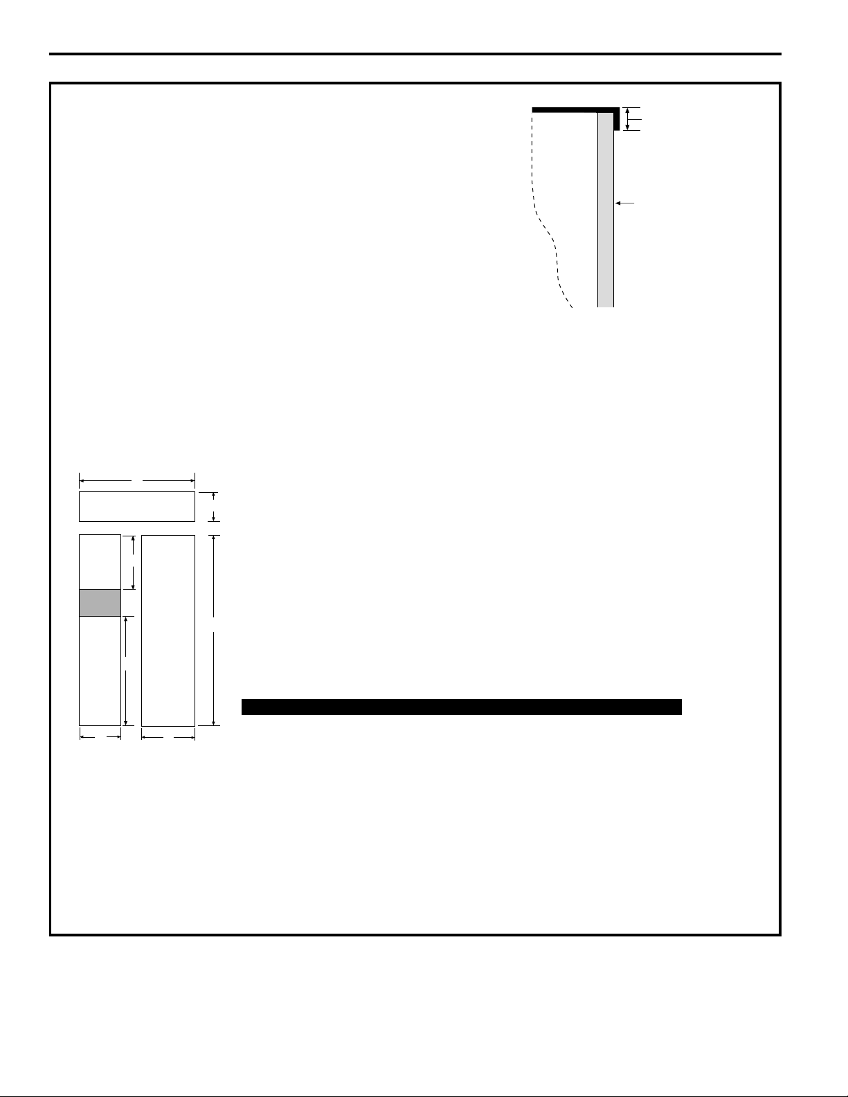
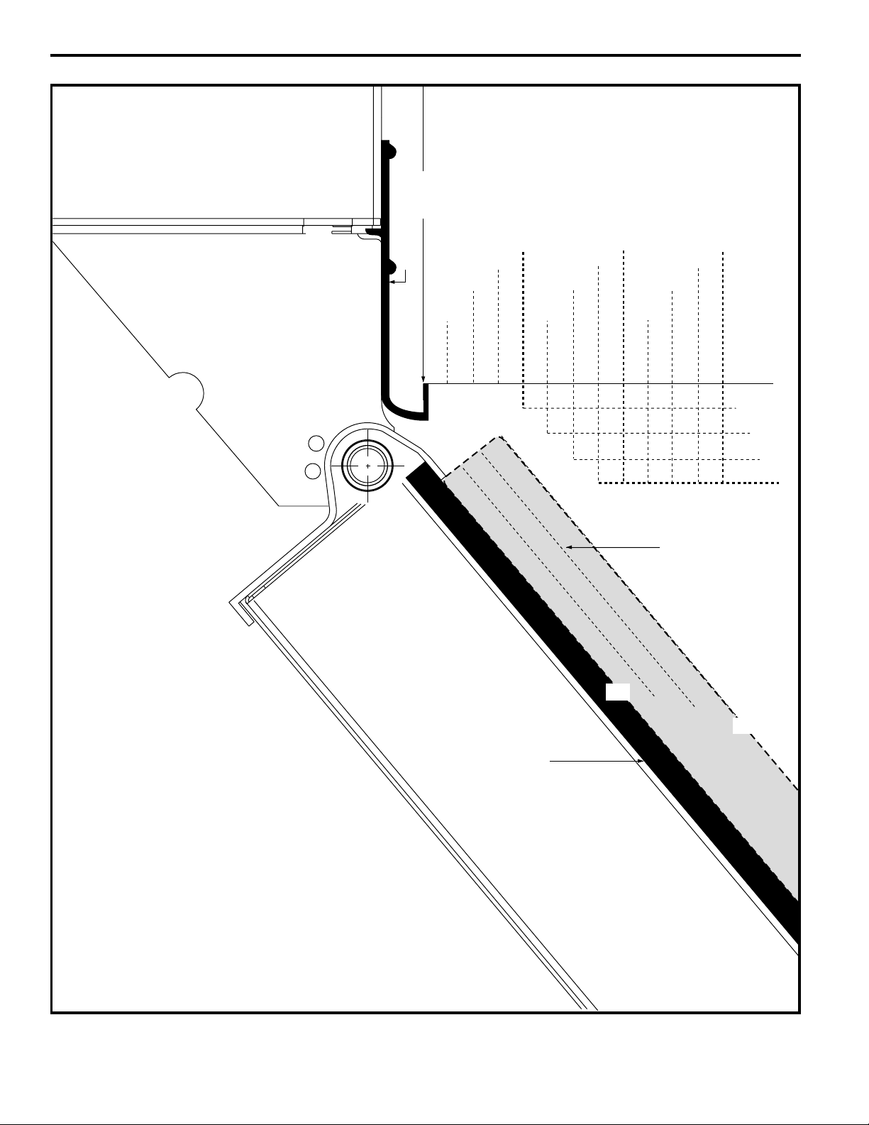
1/4″ FRAMED PANEL DIMENSIONS
If you choose to install framed panels, they
must be cut to the dimensions shown. The
panels will slide into the frame on the door
and grille.
IMPORTANT NOTE: Maximum weight
for Fresh Food panel is 70 pounds and
30 pounds total for Freezer panels.
IMPORTANT NOTE: Dispenser Trim
The refrigerator is supplied with factory installed
dispenser trim.
• If panel is less than 1/4″ thick, a noticeable gap will be
created around the dispenser trim. Foam tape may be
applied on the door to improve the fit.
• If panel is more than 1/4″ thick, the panel will not fit
behind the trim.
E
D
F
A
B
Grille Panel
C
Dispenser
Cutout
Freezer
Panel
Fresh Food
Panel
G
1/4"
Panel
Door
5/16"
Trim
Reveal
Front Panel Dimensions (in inches)
ABCD E F G
42″ Models 39-15/16 10-3/4 67-7/8 16-7/16 22-11/32 17-13/16 35-5/32
Installation Instructions
21
Page 8

3/4″ FRAMED CUSTOM PANEL OPTION
For a more custom appearance, 3/4″ framed custom
panels may be installed on trimmed models. The overlay
panel is secured to a 1/4″ finished backer panel. The
assembled custom panel then slides into the trim with
the same procedure described on page 33.
3/4″ FULL-WIDTH OVERLAY
CUSTOM PANEL OPTION
This design provides a nearly trimless appearance. The full
width overlay panel covers most of the door trim. In this design,
a spacer panel must be installed between the finished backer
and overlay panel.
NOTE: Left-to-right offset is not equal
to top-to-bottom offset.
NOTE: Left-to-right offset is not equal
to top-to-bottom offset.
.250 + .750 = 1.000 Maximum Total Panel Thickness
IMPORTANT NOTE: Maximum total weight for any
assembled Fresh Food panel is 70 pounds and
30 pounds total for Freezer panels.
Installation Instructions
22
.250 + .10 + .750 = 1.100 Maximum Total Panel Thickness
Door
3/4"
Custom
Overlay
Panel
3/4"
1/4"
Backer
Panel
Overlay Panel
Overlay Panel
Backer Panel
Spacer Panel
Backer Panel
Door
1/4"
Backer
Panel
Custom
Overlay
Panel
.10 Inch
Spacer
Page 9

3/4″ FRAMED CUSTOM WOOD PANELS
Secured to a 1/4″ finished backer panel. This design
provides a framed appearance.
Fresh Food Panel
Installation Instructions
23
42″ Models A B
1/4″ Backer Panel 22-5/16″ 67-7/8″
3/4″ Overlay Panel 18-13/16″ 67-1/4″
3-1/8"
1" Thick Max.
or 3/4" Plus
1/4" Backer
1/4" Max.
5/16"
3/8"
Required for Optimal
Handle Clearance
3-1/8" Min.
2-1/2"
B
5/16"
A
Page 10

3/4″ FRAMED CUSTOM WOOD PANELS
Secured to a 1/4″ finished backer panel. This design provides a framed appearance.
Grille Panel
Upper Freezer Panel
Lower Freezer Panel
Installation Instructions
24
42″ Models A B
1/4″ Backer Panel 39-15/16″ 10-3/4″
3/4″ Overlay Panel 39-7/16″ 10-1/8″
42″ Models A B
1/4″ Backer Panel 16-7/16″ 17-13/16″
3/4″ Overlay Panel 12-15/16″ 17-3/16″
42″ Models A B
1/4″ Backer Panel 16-7/16″ 35-1/8″
3/4″ Overlay Panel 12-15/16″ 34-1/2″
1" Thick Max.
or 3/4" Plus
1/4"
1/4" Backer
1/4"
5/16"
5/16"
B
A
1" Thick Max.
or 3/4" Plus
1/4" Backer
3/8"
3-1/8"
5/16"
Required for Optimal
Handle Clearance
3-1/8" Min.
1/4"
Max.
B
5/16"
A
2-1/2"
1" Thick Max.
or 3/4" Plus
1/4" Backer
3/8"
B
3-1/8"
5/16"
5/16"
A
Page 11

3/4″ FULL-WIDTH OVERLAY CUSTOM PANELS
This panel design provides a nearly trimless appearance.
Assemble the spacer
panel onto the finished
backer panel. Allow
1/2″ clearance on the
top, bottom and hinge
side. Allow 3-5/8″ on
the handle side. Secure
the panels with glue.
Be sure to observe
clearances shown on
all sides.
Secure the overlay
panel to the assembled
backer/spacer panel.
Use glue and screws.
Countersink screws
into the backer panel.
Installation Instructions
25
42″ Models A B
1/4″ Backer Panel 22-5/16″ 67-7/8″
0.10″ Spacer Panel 18-3/16″ 66-7/8″
3/4″ Overlay Panel 19-5/16″ 68-1/8″
Fresh Food Panel
Spacer
Panel
Finished
Backer
Panel
3-5/8"
1/2"
1/2"
Required for Optimal
Handle Clearance
1/4"
Max.
3-1/8" Min.
3-1/8"
2-1/2"
B
A
1/2"
Page 12

3/4″ FULL-WIDTH OVERLAY CUSTOM PANELS
This panel design provides a nearly trimless appearance.
Assemble the spacer panel onto the backer panel. Allow 1/2″ clearance on all four sides of the
grille spacer panel. Allow 1/2″ clearance on the top and hinge side, 15/16″ on the bottom and 3-5/8″
on the handle side of the upper freezer door panel. Allow 15/16″ on the top, 1/2″ clearance on the
bottom and hinge side and 3-5/8″ on the handle side of the lower freezer door panel. Secure the
panels with glue. Be sure to observe clearances on all sides.
Secure the appearance panel to the assembled backer/spacer panel. Use glue
and screws. Countersink screws into the backer panel.
Grille Panel
Lower Freezer Panel
Upper Freezer Panel
Installation Instructions
26
42″ Models A B
1/4″ Backer Panel 39-15/16″ 10-3/4″
0.10″ Spacer Panel 38-15/16″ 9-3/4″
3/4″ Overlay Panel 40-3/16″ 11″
42″ Models A B
1/4″ Backer Panel 16-7/16″ 35-1/8″
0.10″ Spacer Panel 12-5/16″ 33-11/16″
3/4″ Overlay Panel 13-7/16″ 34-15/16″
42″ Models A B
1/4″ Backer Panel 16-7/16″ 17-13/16″
0.10″ Spacer Panel 12-5/16″ 16-3/8″
3/4″ Overlay Panel 13-7/16″ 17-5/8″
3-5/8"
15/16"
1/2"
1/2"
Spacer
Panel
Finished
Backer Panel
Spacer
Panel
Finished
Backer Panel
Upper Freezer Panel
Spacer Assembly
Lower Freezer Panel
Spacer Assembly
B
5/16"
5/16"
A
3-1/8"
Required for Optimal
Handle Clearance
3-1/8" Min.
B
2-1/2"
A
3-1/8"
B
A
1/4"
Max.
1/2"
15/16"
1/2"
3-5/8"
Page 13

GROUNDING THE REFRIGERATOR
IMPORTANT—Please read carefully
FOR PERSONAL SAFETY, THIS APPLIANCE
MUST BE PROPERLY GROUNDED.
The power supply cord of this appliance is
equipped with a three-prong (grounding)
plug which mates with a standard threeprong (grounding) wall receptacle to
minimize the possibility of electric shock
hazard from this appliance.
Have the wall outlet and circuit checked by a
qualified electrician to make sure the outlet is
properly grounded.
Where a standard 2-prong wall outlet
is encountered, it is your personal
responsibility and obligation to have it
replaced with a properly grounded 3-prong
wall outlet.
DO NOT, UNDER ANY
CIRCUMSTANCES, CUT
OR REMOVE THE THIRD
(GROUND) PRONG
FROM THE POWER CORD.
DO NOT USE AN ADAPTER PLUG TO
CONNECT THE REFRIGERATOR TO A
2-PRONG OUTLET.
DO NOT USE AN EXTENSION CORD
WITH THIS APPLIANCE.
SIDE PANELS
Side panels (not
supplied) must be
used whenever
the sides of the
refrigerator will be
exposed. The 1/4″
side panels will slip
into the side case
trim. Order side
panels from your
cabinet manufacturer .
*Depending on
installation height.
FLOORING
For proper installation, this refrigerator must
be placed on a level surface of hard material
that is at the same height as the rest of the
flooring. This surface should be strong
enough to support a fully loaded refrigerator,
or approximately 1500 lb.
NOTE: Protect the finish of the flooring. Cut a
large section of the cardboard carton and place
under the refrigerator where you are working.
Installation Instructions
27
24"
*84"
*3" to 4"
1-1/2"
Page 14

1 REMOVE PACKAGING
CAUTION: Refrigerator is
Top-Heavy—be careful when moving.
When using an appliance dolly, handle
from Freezer side only.
• Carefully cut banding at the top and
bottom; remove outer carton.
• Slide out rear corner posts (2).
• Slide carton off top of cabinet.
NOTE: DO NOT LAY CABINET DOWN
IN ORDER TO REMOVE SKID!
• The unit is secured to the skid with
six 7/16″ bolts and six 1/2″ nuts.
• Remove all six 7/16″ bolts that secure
metal brackets to the refrigerator.
• Remove the three 1/2″ nuts and washers
from the Freezer side.
• Remove nut from rear wood block
on Freezer side.
• Tilt unit up on Freezer side toward Fresh
Food side.
• Push bolts down, remove metal bracket
from Freezer side. Remove wood block
from Freezer side.
• Slide the appliance dolly underneath the
Freezer side.
• Using corner posts (2 on front corners)
to prevent damage, secure unit to
appliance dolly.
NOTE: If corner posts are too long, cut the
posts to a shorter length.
• Lift the unit off the skid with the appliance
dolly.
• Remove toekick taped to the top of the
unit.
• Set toekick aside for final installation.
CAUTION: DO NOT ATTEMPT
TO ROLL OR DRAG UNTIL UNIT IS OFF SKID.
CAUTION: MAKE SURE THE
WATER LINE IS CLEAR OF APPLIANCE
DOLLY TO AVOID DAMAGE.
Installation Instructions
28
Toekick Taped to
Top of Unit
Metal
Bracket
1/2" Nuts
Bolts
Page 15

2 INSTALL WATER LINE
• A cold water supply is required for
automatic icemaker operation. The water
pressure must be between 40 and 120 psi.
• Route 1/4″ O.D. copper tubing between
cold water line and the water connection
location.
• Tubing should be long enough to extend
to the front of the refrigerator. Allow
enough tubing to accommodate bend
leading into the water line connection.
NOTE: Certain types of plastic may crack or
rupture with age and cause water damage to
your home.
Shut off the main water supply.
Turn on the nearest faucet long enough
to purge all the water from the line.
• Install a shutoff valve between the
icemaker water valve and cold water pipe
in a basement or cabinet. The shutoff
valve should be located where it will be
easily accessible.
NOTE: It is best to install the valve into a
vertical water pipe. If you install the valve into
a horizontal water pipe, make the connection
at the top or side to avoid drawing off any
sediment from the water pipe.
• Drill a 1/4″ hole in the water pipe.
• Fasten the shutoff valve to the pipe with
pipe clamp.
• Tighten the clamp screws until the
sealing washer begins to swell. Do not
OVERTIGHTEN.
• Place a compression nut and ferrule
(sleeve) for copper tubing onto the end
of the tubing and connect it to the shutoff
valve. Make sure the tubing is fully inserted
into the valve and ferrule is tightened.
• Turn on the main water supply and
flush debris. Run about a quart of water
through the tubing into a bucket. Shut
off water supply at the shutoff valve.
NOTE: Saddle type shutoff valves are
included in many water supply kits. Before
purchasing, make sure a saddle type valve
complies with your local plumbing codes.
NOTE: Commonwealth of Massachusetts
Plumbing Codes 248CMR must be adhered
to. Saddle valves are illegal and use is not
permitted in Massachusetts. Consult with
your licensed plumber.
Installation Instructions
29
Floor
Copper Tubing
Saddle Type
Shutoff Valve
Packing Nut
Outlet Valve
Compression Nut
Ferrule
(Sleeve)
Page 16

3 INSTALL SIDE PANELS
SKIP THIS STEP WHEN NOT USING SIDE P ANELS
If you are using 1/4" side panels, they should be
inserted into the case trim. Fasten the panels to
the refrigerator with the 3M Dual Lock adhesive
strips before setting refrigerator in place.
4A ALTERNATE ANTI-TIP
PRECAUTIONS
SKIP THIS STEP WHEN USING ANTI-TIP
BRACKETS
All Profile built-in refrigerators are Top-Heavy.
They must be secured to prevent the possibility
of tipping forward. Use this alternative method
to secure the refrigerator whenever steel wall
studs are encountered.
• Adjust height of refrigerator to match
installation cutout opening 83-1/2″ to
84-1/2″. The refrigerator must be level and
plumb with cabinets. The top case trim at
the front is 2-1/8″ higher than the rear and
will overlap upper cabinets or cabinet trim.
• Open grille panel to access the top case trim.
• Use a 3/16″ bit to drill 4 evenly spaced
clearance holes through the metal top
case trim.
• Use a 1/16″ bit to drill pilot holes through
the metal clearance holes and into wood
soffit. The holes should be centered in the
soffit or a 3/4″ minimum wood brace. The
brace spanning the enclosure must be
securely fastened to cabinets on both sides.
• Install four 1-1/2″ drywall screws into the
pilot holes.
4
INSTALL ANTI-TIP BRACKETS
WARNING:
The refrigerator is T op-Heavy and must be secured
to prevent the possibility of tipping forward.
•
Cut a 2″ x 4″ wood block 36″ long,
and secure the block to
the mounting
brackets
provided,
using #12 or
#14 wood screws.
•
Secure the
brackets with
wood block to the
back wall so that it is
82″ (or the rear installation height) from the
finished floor. Use #12 or #14 wood screws.
•
Screws must penetrate at least 1″ into vertical
wall studs.
ANTI-TIP
PRECAUTIONS
Positioned
Anti-Tip
Bracket
Wall Stud
(Behind
Drywall)
Wood Screws
Mounted into
Vertical
Wood Studs
36"
Installation Instructions
30
3/4"
Min.
Side View
Top Case Trim
Install (4) 1-1/2" Drywall Screws
Through Trim and Into Soffit
or 3/4" Min. Wood Brace
Top Case Trim
Page 17

7 LEVEL REFRIGERATOR
All models have 4-point leveling. The front and
back are supported by leveling legs. Both are
accessible from the front of the refrigerator.
• To level the back of the refrigerator, turn
the 1/2″ hex nut located above the front
wheels. Turn clockwise to raise or
counterclockwise to lower the refrigerator.
• For front leveling, use a 7/16″ open-end
wrench.
• Adjust height of refrigerator to match
installation cutout opening 83-1/2″ to
84-1/2″. The refrigerator should be level
and plumb with cabinets.
IMPORTANT NOTE: The refrigerator must
be level. If it is not, the doors may not align
evenly at the top. See Step 16.
CAUTION:
The rear leveling legs and front leveling legs
are limited to a maximum height adjustment
of 1″. If the installation requires more than
84-1/2″ height, the installer should elevate the
refrigerator on a sheet of plywood or runners.
Cabinet trim could be added across the top
of the opening to shorten the opening. If you
attempt to raise the refrigerator more than
1″, you will damage the front and rear
leveling legs.
5 CONNECT POWER
• Connect refrigerator power cord plug to
a properly grounded receptacle. Set the
Master Power switch to the I (ON) position.
• Check to make sure power to refrigerator
is on by opening refrigerator door to see if
interior lights are on.
CAUTION:
• After power has been established, turn the
Master Power switch to the O (OFF) position.
6 MOVE INTO
INSTALLATION SPACE
• Slide the unit into the installation space.
• Place excess slack in the power cord on top
of the refrigerator.
• Use care to ensure the power cord is not
pinched behind the unit.
Installation Instructions
31
Raise
Grille
Panel
Master
Power Switch
Height
from
Floor to
Bottom
of Wood
Block
82"
Leveling Leg
Hex Nut Adjusts
Rear Leveling Legs
Page 18

10 INSTALL GRILLE PANEL
• Raise the grille panel to the stop position.
• Remove 4 screws on bottom trim; retain
all screws.
• Remove bottom trim.
• NOTE: Stainless steel and acrylic panels
are covered with a protective film. Remove
the film before installing the panel.
• Slide panel over the metal backer panel
and under the trim.
• If necessary, tap with a wood block until
panel slips under the top trim piece.
• Reassemble bottom trim. Tighten screws.
8 SECURE REFRIGERATOR
TO CABINETS
Whenever possible, perform this step for
anti-tip security.
The refrigerator must be secured to prevent
tipping.
• Raise the grille panel to access case trim.
• Drive a screw through the trim and into the
adjacent cabinet using holes provided.
• Follow the same procedure on the opposite
side.
9 ADJUST DOOR SWING
NOTE: This refrigerator has a 2-position door
stop. When space does not allow the door to
swing open fully to 130°, you may change the
door swing to a 90° opening.
SKIP THIS STEP IF DOOR OPENING IS
SATISFACTORY FOR YOUR INSTALLATION
SITUATION.
• Open the door to view the bottom hinge.
Note the door stop pin location. The pin is
factory installed in the 130° position.
• Partially close the door. From above, use a
flat-head screwdriver to unscrew the door
stop pin and reinstall into the 90° position.
Installation Instructions
32
Raise Grille Panel
to Stop Position
Drive Screws
Through Case Trim Into
Adjacent Cabinets
Raise
Grille
Panel
Interior
90°
130°
Door
Hinge
Page 19

11A
Install 1/4″ Decorative Panels:
• Remove Handles
Open door to 90°. Remove 5 Phillips head
screws from the Fresh Food and Freezer
door handles; retain all screws. Lift off
door handles.
• Install Door Panels
NOTE: Stainless steel and acrylic panels are
covered with a protective film. Remove the
film before installing the panel. Carefully
push the Fresh Food panel in until it slides
into the slot behind the trim. Gently push to
opposite side. Repeat procedure for upper
and lower Freezer panels.
• Reinstall Handles
Reinstall Fresh Food door handle with the
original 5 Phillips head screws. Tighten.
Repeat for Freezer door handle.
NOTE: Ensure that the edge of the handle
does not pinch the door gasket.
• 3/4″ Custom Decorative Panels
If you choose to install custom wood
panels, they must be cut to dimensions
shown on pages 23–26. The panels will
slide into the frame on the doors
and grille.
IMPORTANT NOTE: Maximum custom panel
thickness must not exceed 1-1/8″ thick and
70 lb for Fresh Food door, 30 lb total for
Freezer door and 15 lb for Grille panel.
Installation Instructions
33
INSTALL DOOR PANELS ON TRIMMED MODELS
Handle
Fresh Food
Refrigerator
Door
3/4" Custom Panel
if Required
Page 20

11B
1. Remove handles from cartoning and any other protective packaging.
2. Place handle over pre-installed shoulder bolts (A) that are fastened into door in four locations.
3. While supporting handle and looking at upper end cap, fasten top-most allen set screw (B) with
supplied allen wrench, then fasten bottom allen set screw (C). See Figure 1.
4. Repeat Step 3 with bottom end cap using allen set screws (D and E), once upper section of
handle is firmly secured to door. See Figure 2.
5. All set screws should be tightened and sub-flush (allen set screw should be buried just below
the surface of the end cap) of handle end cap. The end caps should be drawn tight to freezer
and refrigerator doors with no gaps.
Installation Instructions
34
INSTALL DOOR HANDLES ON STAINLESS STEEL MODELS
AA
B
C
AA
D
E
Figure 1
Upper End Cap
Figure 2
Bottom End Cap
Page 21

13 TURN ON THE POWER
• Set the Master Power switch to the I (ON)
position.
• Check to make sure power to refrigerator is
on by opening refrigerator door to see if
interior lights are on.
• The temperature controls are preset at 37°
for the Fresh Food section and 0° for the
Freezer section.
• Allow 24 hours to stabilize before making
adjustments.
• Dispense water for 2 minutes to remove
trapped air from the water system.
12 CONNECT WATER SUPPLY
Check to make sure that Master Power
switch is in the O (OFF) position.
• Locate and bring tubing to the front of the
cabinet.
• Turn the water on to flush debris from line.
Run about a quart of water through tubing
into a bucket, then shut off water.
Copper Tubing
• Slip a 1/4″ nut and ferrule onto end of
copper tubing. Insert tube into the union
fitting on the unit and tighten nut to union.
• Turn on the water to check for leaks.
Note: Make sure excess tubing length does
not interfere with toekick installation.
Installation Instructions
35
Refrigerator
Water Supply
House
Water Supply
Raise
Grille
Panel
Master
Power Switch
Page 22

16 DOOR ALIGNMENT
• Stand back from the refrigerator to inspect
the door alignment.
• Shipping or the addition of heavy door
panels may have caused the doors to move
slightly out of alignment.
• If necessary, the Fresh Food door may
be adjusted up or down to align with the
Freezer door.
• Loosen the leveling mechanism.
• Use a 7/32″ wrench to adjust the hinge pin
as shown.
• Tighten the leveling mechanism.
IMPORTANT NOTE: After the unit has been
leveled, if the fresh food door is higher than
the freezer door, adjust the front right leveling
leg lower to align the doors and, if required,
raise the left leveling leg to level the unit side
to side.
14 START ICEMAKER
• Flip the switch to I (ON). The icemaker will
begin operation automatically.
• Make sure nothing interferes with the
sweep of the feeler arm.
• Discard the first full bucket of ice cubes.
• To turn the icemaker off, set the switch to
O (OFF).
15 INSTALL TOEKICK
• Locate the supplied toekick (shipped taped
to the top of the refrigerator). Install with
2 screws provided.
• The vented toekick must remain unobstructed
for proper air flow.
Installation Instructions
36
Power Switch
Feeler Arm
Green Power Light
Bushing
Door Hinge
Case Hinge
7/32" Wrench
Raise
Clockwise
 Loading...