

Page 1
DF7190
DF7290
Einbau-Flachschirm-Dunstabzugshaube
Built-In- Flat-Screen Fume Extractor Hood
Hottes aspirantes encastrables à visière plate
Cappa aspirante da incasso con schermo piatto
estraibile
Inbouw-wasemkappen met plat scherm
Campana empotrable de aspiración de vahos con
visiera plana
Montage- und Gebrauchsanweisung
Installation and Operating Instructions
Instructions de montage et mode d'emploi
Istruzioni di montaggio e per l'uso
Montage- en gebruiksaanwijzing
Instrucciones de montaje y para el uso
Page 2

Bedienungsanleitung
INHALTSVERZEICHNIS
EMPFEHLUNGEN UND HINWEISE......................................................................................................................................8
CHARAKTERISTIKEN...........................................................................................................................................................9
MONTAGE............................................................................................................................................................................10
BEDIENUNG........................................................................................................................................................................12
WARTUNG...........................................................................................................................................................................13
DE
2
2
Page 3
RECOMMENDATIONS AND SUGGESTIONS
650 mm min.
INSTALLATION
• The manufacturer will not be held liable for any damages resulting
from incorrect or improper installation.
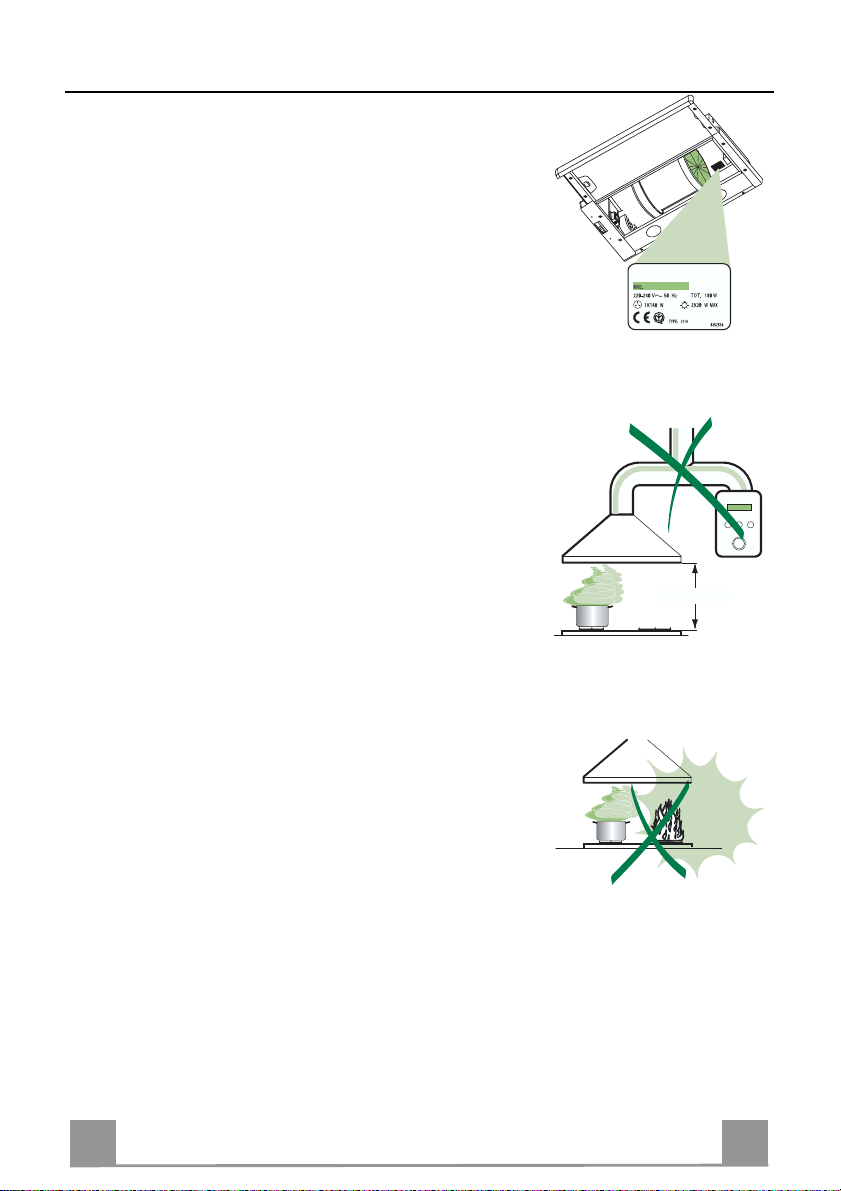
• The minimum safety distance between the cooker top and the extrac tor hood is 650 mm.
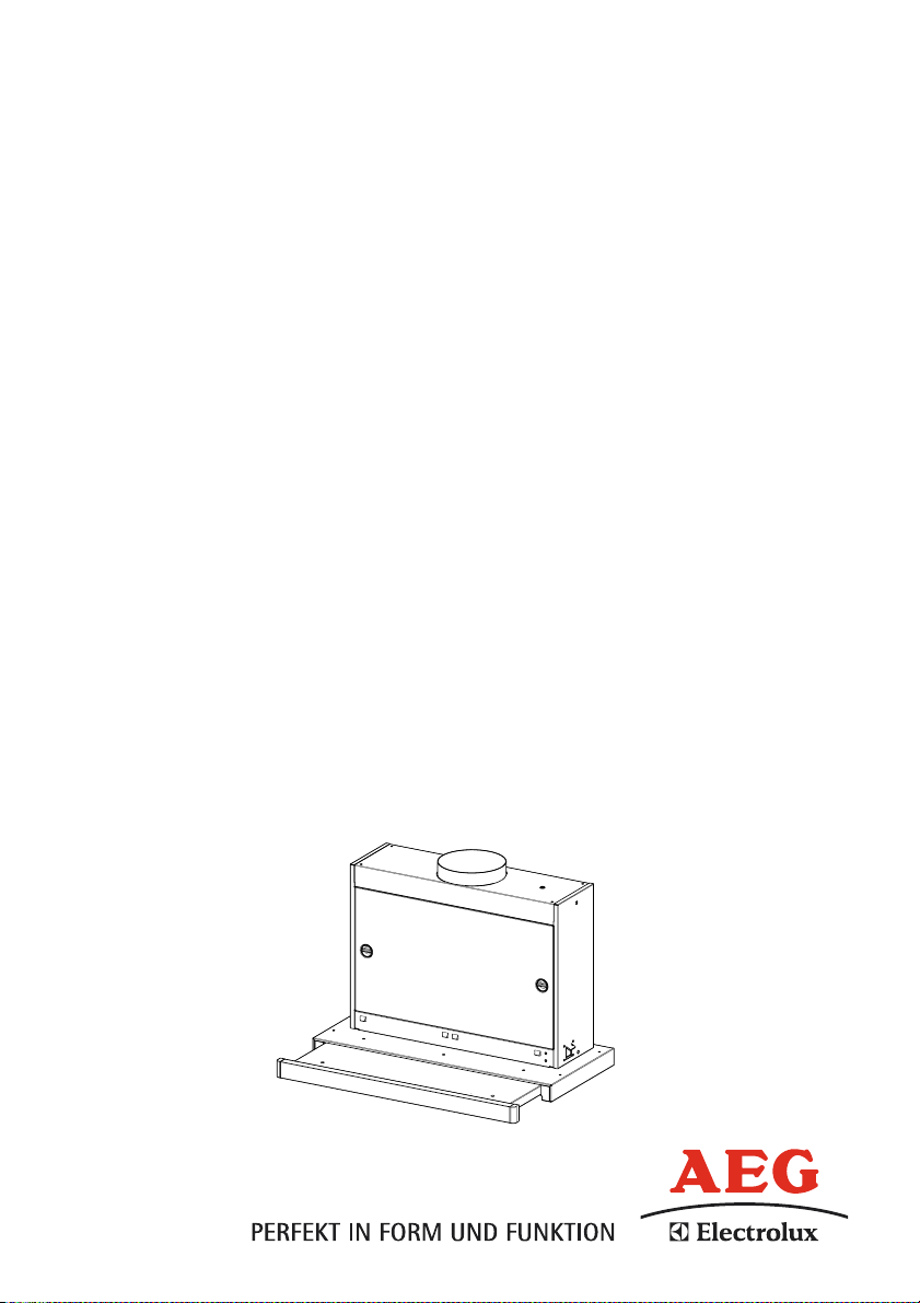
• Check that the mains voltage corresponds to that indicated on the
rating plate fixed to the inside of the hood.
• For Class I applianc es, c heck t hat th e domes tic po wer suppl y gua rantees adequate earthing.
Connect the extractor to the ex haust flue through a pi pe of minimum
diameter 120 mm. The route of the flue must be as short as possible.
• Do not connect the extractor hood to exhaust ducts carryi ng combustion fumes (boilers, fireplaces, etc.).
• If the extractor is used in conj unction with non-electrical appliances
(e.g. gas burning appliances), a suffici ent degree of aeration must be
guaranteed in the room in order to prevent the backflow of exhaust
gas. The kitchen must have an opening communicating directl y with
the open air in order to guarantee the entry of clean air.
USE
• The extractor hood has been designe d ex cl usi vely for domesti c us e to
eliminate kitchen smells.
• Never use the hood for purposes ot her than for which it has ben designed.
• Never leave high naked flames under the hood when it is in operation.
• Adjust the flame intensity to direct it onto the bottom of the pan only,
making sure that it does not engulf the sides.
• Deep fat fryers must be continuously monitored during use: overheated oil can burst into flames.
• The hood should not be used by chil dren or persons not inst ructed in
its correct use.
MAINTENANCE
• Switch off or unplug the appliance from the mains supply before carrying out any maintenance work.
• Clean and/or replace the Filters after the specified time period.
• Clean the hood using a damp cloth and a neutral liquid detergent.
EN
1
14
Page 4

CHARACTERISTICS
Dimensions
Components
Ref. Q.ty Product Components
1 1 Hood Body, complete with: Controls, Light, Blower,
8 1 Directional Air Outlet grille
9 1 Flange ø 150 mm
10a 1 Flange ø 120 mm
10b 1 Adapting ring ø 120-125 mm
20 1 Closing element
Ref. Q.ty Installation Components
7.1 2 Hood Body Fixing Brackets
12a 8 Screws 3,5 x 16
12e 2 Screws 2,9 x 12,7
12f 5 Screws 2,9 x 9,5
Filters
Q.ty Documentation
1 Instruction Manual
EN
12f
12e
8
9
12a
7.1
1
12a
20
10b
10a
12a
7.1
1
15
Page 5

INSTALLATION
1 2 3
4 6
Vr
7
8
9
5
Drilling the Support surface and Fitting the Hood
• The Hood can be fitted directly on the
lower surface of the Wall Units (650 mm
min. above the Cooker Top) using the snapon Side Supports.
• Make an opening on the lower surface of
the Wall Unit, as indicated. (fig.1)
• If the cabinet is without bottom, fix the two
brackets at a distance B of minimum 30mm
and maximum 60mm. (fig.2)
• Before carrying out the installation, the
wooden transportation protections screwed
on the visor and on the canopy body must
be removed. (fig.3)
• Choose the correct flange measure basing
on the air outlet diameter and insert it to the
upper air outlet opening. (fig.4)
• Screw the closing profile 20 onto the rear
part of the hood, using the screws 12f (2.9
x 9.5) provided. (fig.5)
• Open the sliding suction panel.
• Remove the metal grease filters one by one
by turning the hooks provided.
• Close the sliding suction panel again.
• Insert the Hood until the snap-on side supports click into place. (fig.6)
• Open the sliding suction panel.
• Lock in position by tightening the screws
Vf from underneath the Hood. (fig.6)
• If necessary, adjust the whole filter holder
unit and proceed as follows:
• Loosen the four adjustment screws Vr
and close the sliding panel again. (fig.7)
• Move the entire filter holder unit until it
is properly aligned with the wall unit.
(fig.8)
• Keeping the hood canopy still, remove
the sliding panel and lock the adjustment
screws again. (fig.7)
• The hood can now be fastened to the
wall unit using the four screws 12a (3.5
x 16) provided. (fig.9)
• Replace the metal grease filters.
• Close the sliding suction panel again.
162
523
10b
10a
9
10a
12a
EN
1
16
Page 6

Connections
DUCTING VERSION AIR EXHAUST SYSTEM
When installing the hood in ducting version, a rigid or a
flexible pipe with the diameter corresponding to the
flange diameter is used in order to connect the hood to
the air outlet piping.
• Fix the pipe with an adequate quantity of pipe
clamps (not supplied).
• Remove possible charcoal filters.
RECIRCULATION VERSION AIR OUTLET
• Cut a hole ø 125 mm in any shelf that may be positioned over the hood.
• Insert the flange 10a on the hood body outlet.
• Connect the flange to the outlet on the shelf over the
hood using a flexible or rigid pipe ø120 mm.
• Fix the pipe in position using sufficient pipe clamps
(not supplied).
• Fix the directional grille 8 on the recirculation air
outlet using the 2 screws 12e (2,9 x 12,7) provided.
• Ensure that the activated charcoal filters have been
inserted.
12e
8
ELECTRICAL CONNECTION
• Connect the hood to the mains through a two-pole switch having a contact gap of at least 3
mm..
EN
1
17
Page 7

USE
L
M
By pulling out the sliding panel it is possible to automatically activate all the hood functions.
By simply closing the sliding panel all the functions are switched off.
SWITCH FUNCTIONS
L Light Switches the lighting system on and off
M Motor Switches the extractor motor on and off
1. Low speed, used for a continuous and silent air change in the presence
of light cooking vapour.
2. Medium speed, suitable for most operating conditions, thanks to an optimum relation between hood performance and noise.
3. Maximum speed, suitable when the highest cooking vapour emission
has to be eliminated for longer periods.
i. Intensive speed, suitable for the strongest cooking vapours and odours.
EN
1
18
Page 8

MAINTENANCE
Grease filters
CLEANING METAL CASSETTE GREASE FILTERS
• The filters must be cleaned every 2 months, or more frequently
in case of particularly heavy use of the hood. Filters can be
washed in a dishwasher.
• Pull out the sliding suction panel.
• Remove the filters one by one, after having disconnected the
relative fastening elements.
• Wash the filters, taking care not to bend them. Let them get dry
before refitting them. (The colour of the filter surface may
change throughout the time but this has no influence to the filter efficiency).
• When refitting the filters, make sure that the handle is visible
on the outside.
• Close the sliding suction panel.
Charcoal filter (Recycling version)
REPLACING CHARCOAL FILTERS
• These filters are not washable and cannot be regenerated, and
must be replaced approximately every four months or more
frequently by particularly heavy use.
• Pull out the sliding suction panel.
• Remove the grease filters.
• Remove the saturated carbon filter by releasing the fixing
hooks
• Replace the grease filters.
• Close the sliding suction panel.
Lighting
LIGHT REPLACEMENT
11 W fluorescent light.
• Remove the metal terminals fixing the glass.
• Slide the glass cover to the right until the left hand is free.
Lower it slightly and slide it to the left to free it completely.
• Replace the light with a new one of the same type and rating.
• Replace the glass cover in reverse order.
EN
1
19
Page 9

Bitte geben Sie unserem Kundendienst folgende Angaben bei einer
Störung an:
If your appliance has a fault, please contact our service engineer and
state the following numbers:
Veuillez donner les indications suivantes à notre service après-vente en
cas de panne:
Qualora constataste un difetto vi preghiamo di comunicare i seguenti
dati al nostro servizio tecnico assistenza clienti:
Geef onze klantenservice bij een storing de volgende gegevens op:
Por favor suministre a nuestro Servicio Postventa los datos siguientes
al haber ocurrido una avería:
E-Nr. 610
F-Nr.
AEG Hausgeräte GmbH
Postfach 1036
D-90327 Nürnberg
© Copyright by AEG
436002988_ver2
Dir. 89/336/CEE
73/23/CEE
93/68/CEE
 Loading...