

Page 1

DD 8693
DD 8623
Dunstabzugshaube
Afzuigkap
Hotte aspirante
Cooker Hood
Cappa aspirante
Montage- und Gebrauchsanweisung
Installatie- en gebruiksaanwijzing
Manuel de montage et d’utilisation
Operating and Installation Instructions
Istruzioni di montaggio ed uso
Page 2

Printed on recycled paper
AEG - putting words into action
62
Page 3

Contents
Safety warnings 6 2
for the user 62
for the installer 62
Description of the Appliance 6 4
Extractor version 64
Filter Version 65
Hood Operation 6 6
Filter checking device for the detection of grease and active carbon 67
Led – Indicator for grease filter 67
Led - indicator for active carbon filter 67
Resetting the saturation indicator 67
Maintenance and care 68
Metal grease filter 68
Open the metal grease filter 68
Charcoal filter 69
Changing the light bulb 70
Cleaning 7 1
Special accessories 71
T echnical assistance service 7 1
Guarantee conditions 7 2
T echnic Details 74
Mounting accessories included 74
Electrical connection 7 5
Safety warnings for the electrician 75
Wall unit mounting 7 6
63
Page 4

Safety warnings
for the user
• Always cover lighted elements, to prevent excess heat from
damaging the appliance. In the case of oil, gas and coal fired
cookers it is essential to avoid open flames.
• Also, when frying, keep the deep frying pan on the cooker top/cooker
under careful control.
• The hot oil in the frying pan might ignite due to overheating.
• The risk of self-ignition increases when the oil being used is dirty .
• It is extremely important to note that overheating can cause a fire.
• Never carry out any flambé cooking under the hood.
• Always disconnect the unit from the power supply before
carrying out any work on the hood, including replacing the
light bulb (take the cartridge fuse out of the fuse holder or switch off
the automatic circuit breaker).
• It is very important to clean the hood and replace the filter at
the recommended intervals. Failure to do so could cause
grease deposits to build up, resulting in a fire hazard.
for the installer
• When used as an extractor unit, the hood must be fitted with a
150mm diameter hose.
• Should there already be a pipe of diameter 125 mm that ducts to the
outside through the walls or roof, it is possible to use the 150/125
mm reduction flange provided. In this case the hood will be slightly
more noisy .
• When installing the hood, make sure you respect the following
minimum distance from the top edge of the cooking hob/ring
surfaces:
electric cookers 500 mm
gas cookers 650 mm
coal and oil cookers 700 mm min.
• The national Standard on fuel-burning systems specifies a maximum
depression of 0.04 bar in such rooms.
• The air outlet must not be connected to chimney flues or combustion
gas ducts. The air outlet must under no circumstances be connected
to ventilation ducts for rooms in which fuel-burning appliances are
installed.
64
Page 5

• It is advisable to apply for authorization from the relevant controlling
authority when connecting the outlet to an unused chimney flue or
combustion gas duct.
The air outlet installation must comply with the regulations laid down
by the relevant authorities.
• When the unit is used in its extractor version, a sufficiently large
ventilation hole must be provided, with dimensions that are
approximately the same as the outlet hole.
• National and regional building regulations impose a number of
restrictions on using hoods and fuel-burning appliances connected to
a chimney , such as coal or oil room-heaters and gas fires, in the
same room.
• Hoods can only be used safely with appliances connected to a
chimney if the room and/or flat (air/environment combination) is
ventilated from outside using a suitable ventilation hole approximately
500-600 cm2 large to avoid the possibility of a depression being
created during operation of the hood.
• If you have any doubts, contact the relevant controlling authority or
building inspector’s office.
• Since the rule for rooms with fuel burning appliances is “outlet hole of
the same size as the ventilation hole”, a hole of 500-600 cm2, which
is to say a larger hole, could reduce the performance of the extractor
hood.
• If the hood is used in its filtering function, it will operate simply and
safely in the above conditions without the need for any of the
aforementioned measures.
• When the hood is used in its extractor function, the following rules
must be followed to obtain optimal operation:
— short and straight outlet hose
— keep bends in outlet hose to a minimum
— never install the hoses with an acute angle, they must
always follow a gentle curve only
— keep the hose as large as possible (preferably the same diameter
as the outlet hole).
• Failure to observe these basic instructions will drastically reduce the
performance and increase the noise levels of the extractor hood.
65
Page 6

Description of the Appliance
Extractor version
• The hood is supplied as an extractor unit and can also be used with
a filtering function by fitting one charcoal filter (special accessory).
• Y ou will need original AEG charcoal filter for this function (see
Special Accessories).
• The air is discharged to the outside through a pipe, which must be
fitted to connection flange D. Fig. 1.
• In order to obtain the best performance the hose should have a
diameter equal to the outlet hole.
Should there already be a pipe of diameter 125 mm that ducts to the
outside through the walls or roof, it is possible to use the 150/125
mm reduction flange provided. In this case the hood will be slightly
more noisy .
D
66
Fig. 1
Page 7
Filter Version
• The air is filtered through an charcoal filter and returned to the
kitchen through the top grill of the outlet pipe.
• Y ou will need an original AEG KF20 charcoal filter for the filtering
function. (See Special Accessories).
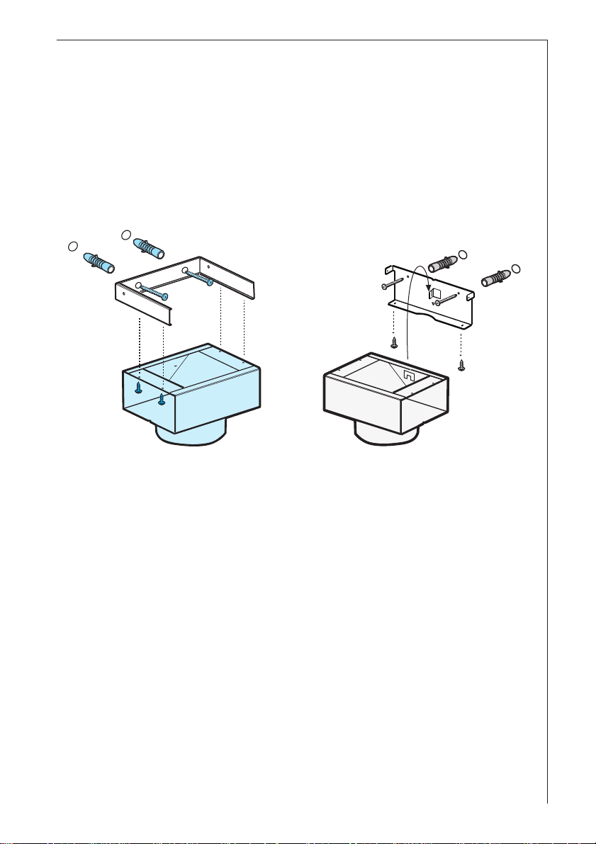
• Fix the deflector using 4 screws Ø 2,9x6.5 mm (2 screws for hood
model DD 8623). Fig. 2.
Fig. 2 - DD 8693 Fig. 2 - DD 8623
67
Page 8
Hood Operation
• Best results are obtained by using a low speed for normal conditions
and high speed when odours are more concentrated. Turn the hood
on a few minutes before you start cooking then you will get an
underpressure in the kitchen. It should be left on after cooking for
about 15 minutes or until all odours have disappeared.
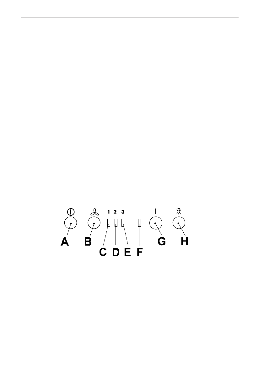
The control switches are located on the unit’s front panel:
A - Main switch, hood OFF.
B - Start and choice of motor speed 1-2-3-1-2.........
C - Indicates speed 1 (LED) and indication of the grease saturation
for the filter (flashing indicator).
D - Indicates speed 2 (LED) and indication of the active carbon
saturation for the filter (flashing indicator).
E - Indicates speed 3
F - Indicates Intensive speed (LED).
G - Intensive speed on/off. The Intensive speed runs for 5 minutes:
If the hood is on when the Intensive speed is activated, the hood
revert to previous speed after 5 minutes.
If the hood is off when the Intensive speed is activated, the hood
will automaticly be turned off after 5 minutes.
T o interrupt the Intensive speed, press button A or B.
H - Light ON/OFF
Should the hood or the controls fail to operate: disconnect the power
supply for at least 5 seconds, then turn the hood back on again.
68
Page 9

Filter checking device for the detection of
grease and active carbon
This type of vapour hood is predisposed with a device that signals when
the grease or active carbon filter requires cleaning (sold with the active
carbon filter by the manufacturer specialized in ventilation equipment).
This type of vapour hood is supplied by the manufacturer without the
active carbon filter, therefore the saturation signal is disabled.
The hood is purchased with active carbon filter included, and the
saturation signal is activated as follows:
Depress and hold the A and B buttons simultaneously for 3 seconds.
Initially only the LED indicator signal for the grease filter C is activated,
shortly after the LED indicator for the active carbon filter D will activate,
at this point the saturation detection has been enabled.
T o switch of f the saturation detection : depress and hold the A and B
buttons for 3 seconds until the LED indicator for the active carbon filter
is flashing.
Led – Indicator for grease filter C
The LED indicator for the grease filter will flash when it requires
cleaning.
Follow the maintenance instructions.
Led - indicator for active carbon filter D
The LED indicator for the active carbon filter illuminates when the filter
requires replacing.
This occurs after about 160 working hours from when the active carbon
filter was first put into operation.
Resetting the saturation indicator
After cleaning the filter depress and hold the G and H buttons again for
3 seconds until the LED – grease filter indicator or the LED – active
carbon indicator D are no longer flashing.
69
Page 10
Maintenance and care
• The hood must always be disconnected from the electricity
supply before beginning any maintenance work.
Metal grease filter
• The purpose of the grease filters is to aspirate grease particles which
form during cooking and it must always be used, either in the
external evacuation or internal recycling function.
Attention: the metal grease filters must be removed and washed,
either by hand or in the dishwasher, every four weeks.
Open the metal grease filter
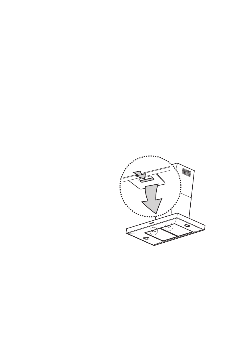
• First, push the metal grease filter stop backwards, then extract the
filter, pulling downwards. Fig. 3.
Hand washing
Soak grease filters for about
one hour in hot water with a
grease-loosening cleaner,
then rinse off thoroughly with
hot water. Repeat the process
if necessary . Refit the grease
filters when they are dry .
Dishwasher machine
Place grease filters in dish
washer. Select most powerful
washing programme and
highest temperature, at least
65°C. Repeat the process.
Refit the grease filters when
they are dry .
When washing the metal
grease filter in the dishwasher a slight discoloration of the filter can
occur, this does not have any impact on its performance.
• Clean the inner housing using a hot detergent solution only (never
use caustic detergents, abrasive powders or brushes).
70
Fig. 3
Page 11
Charcoal filter
• The charcoal filter should only be used if you want to use the hood in
its filtering function.
• T o do this you will need an original AEG charcoal filter (see special
accessories).
• Cleaning/replacing the charcoal filter
Unlike other charcoal filters, the LONGLIFE charcoal filter can be
cleaned and reactivated. At normal use the filter should be cleaned
every second month. The best way to clean the filter is in the
dishwasher. Use normal detergent and choose the highest temperature (65º C). Wash the filter separately so that no food parts gets
stuck on the filter and later causes bad odours. T o reactivate the
charcoal, the filter should be dried in an oven for 10 minutes with a
temperature of maximum 100º C.
After approximately three years of use, the charcoal filter should be
replaced with a new, as the odour reduction capacity will be reduced.
• Mounting
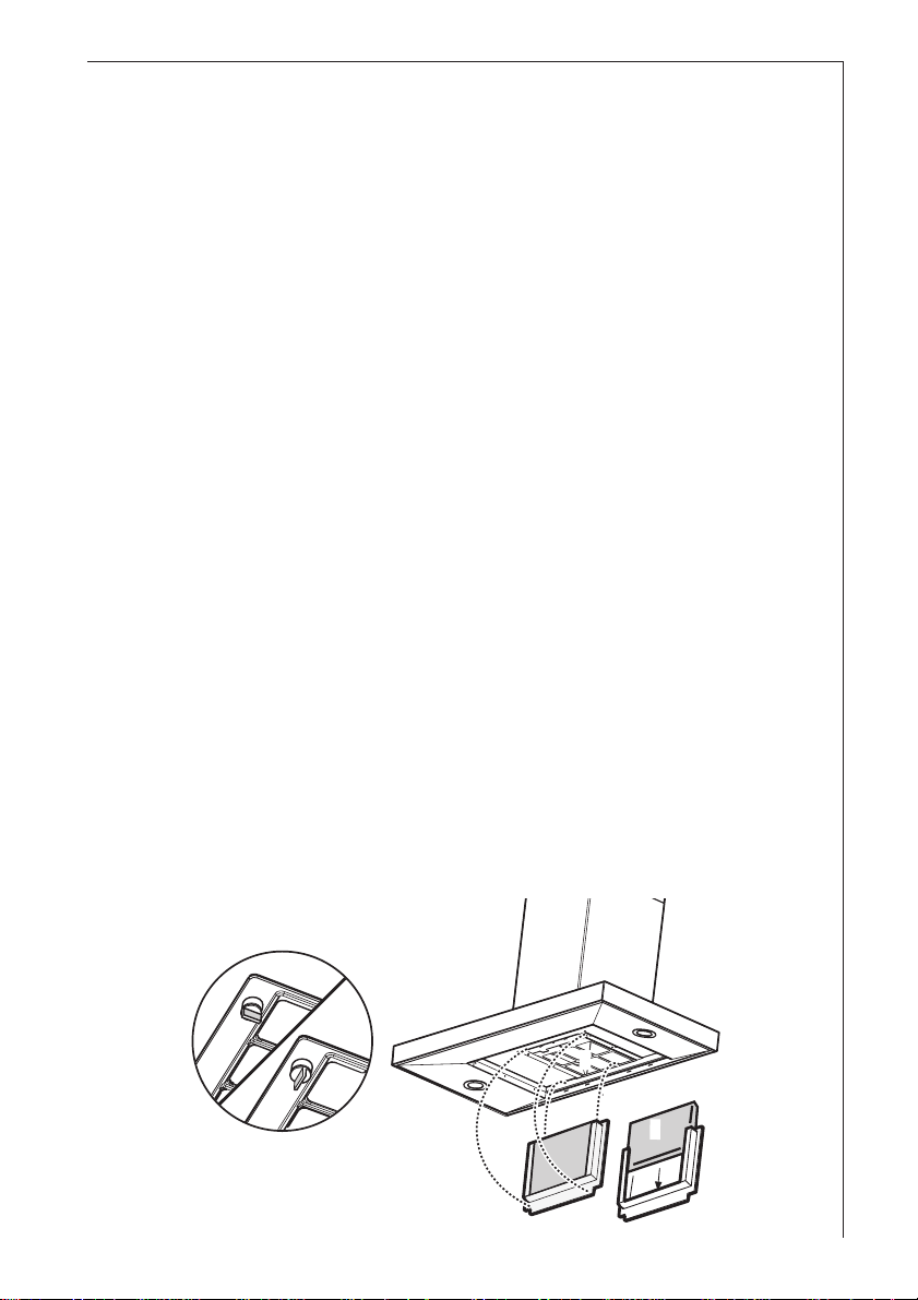
Remove the frame b which supports the filter c by turning 90° the
two knobs a, Fig.4. Insert the coal mattress inside the frame and
put all parts back in their place d.
• T o dismount proceed in reverse order.
• Always specify the hood model code number and serial number
when ordering replacement filters. This information is shown on the
registration plate located on the inside of the unit.
• The charcoal filter can be ordered from the AEG technical assistance
service.
a
d
a
c
b
Fig. 4
a
a
71
Page 12
Warning
• Failure to observe the instructions on cleaning the unit and changing
the filters will cause a fire hazard. Y ou are therefore strongly
recommended to follow these instructions.
• The manufacturer declines all responsibility for any damage to the
motor or any fire damage linked to inappropriate maintenance or
failure to observe the above safety recommendations.
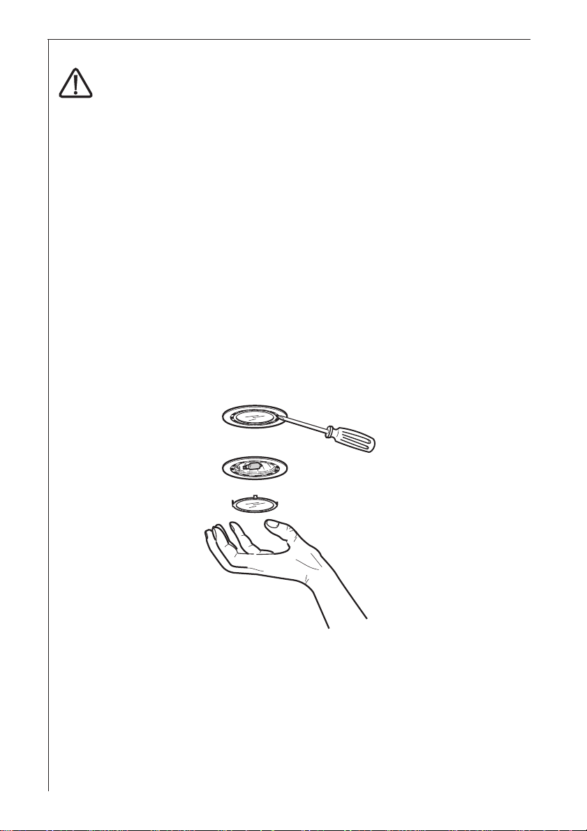
Changing the light bulb
• Disconnect the cooker hood from the main supply .
• Remove the lamp cover, use a screw driver as a lever . Fig. 5.
• Replace the old bulb with a new one of the same type.
• Remount the lamp cover.
• If the light does not come on, make sure the bulb has been inserted
in correctly before contacting the technical assistance service.
72
Fig. 5
Page 13

Cleaning
• Warning: always disconnect the hood from the mains power supply
before cleaning it.
Never insert pointed objects in the motor’s protective grid.
• Wash the outside surfaces using a delicate detergent solution. Never
use caustic detergents or abrasive brushes or powders.
• Only ever clean the switch panel and filter grille using a damp cloth
and delicate detergents.
• It is extremely important to clean the unit and change the filters at
the recommended intervals. Failure to do so will cause grease
deposits to build up that could constitute a fire hazard.
Special accessories
Charcoal filter KF20 942 120 600
T echnical assistance service
Y ou are welcome to telephone our technical assistance service (see list
of technical assistance centres) whenever you need information or in the
unlikely event of a fault.
When calling, please be ready to specify:
1. The model code number
2. The serial number (E-Nr.)
3. The manufacturing number (F-Nr.)
This information is shown on the registration plate inside the unit
behind the grease filter.
We reserve the right to change specifications and colours as a result of
our policy of continuing technological development.
73
Page 14

Guarantee conditions
Guarantee Conditions
AEG offer the following guarantee to the first purchaser of this appliance.
1. The guarantee is valid for 12 months commencing when the appliance
is handed over to the first retail purchaser, which must be verified by
purchase invoice or similar documentation.The guarantee does not
cover commercial use.
2. The guarantee covers all parts or components which fail due to faulty
workmanship or faulty materials. The guarantee does not cover
appliances where defects or poor performance are due to misuse,
accidental damage, neglect, faulty installation, unauthorised
modification or attempted repair, commercial use or failure to observe
requirements and recommendations set out in the instruction book.This
guarantee does not cover such parts as light bulbs, removable glassware or plastic.
3. Should guarantee repairs be necessary the purchaser must inform the
nearest customer service office (manufacturer`s service or authorised
agent). AEG reserves the right to stipulate the place of the repair
(i.e.the customer`s home, place of installation or AEG workshop).
4. The guarantee or free replacement includes both labour and materials.
5. Repairs carried out under guarantee do not extend the guarantee
period for the appliance. Parts removed during guarantee repairs
become the property of AEG.
6. The purchaser`s statutory rights are not affected by this guarantee.
European Guarantee
If you should move to another country within Europe then your guarantee
moves with you to your new home subject to the following qualifications:
- The guarantee starts from the date you first purchased your product.
- The guarantee is for the same period and to the same extent for labour
and parts as exist in the new country of use for this brand or range of
products.
- This guarantee relates to you an cannot be transferred to another user .
- Your new home is within the European Community (EC) or European
Free Trade Area.
- The product is installed and used in accordance with our instructions
and is only used domestically , i.e. a normal household.
- The product is installed taking into account regulations in your new
country .
74
Page 15

Before you move please contact your nearest Customer Care Centre, listed
below, to give them details of your new home.They will then ensure that the
local Service Organisation is aware of your move and able to look after you and
your appliances.
France Senlis +33 (0) 44 62 29 29
Germany Nürnberg +49 (0) 911 323 2600
ItalyPordenone+39 800 11 75 11
Sweden Stockholm +46 (0) 8 738 7910
UK Slough +44 (0) 1753 219899
75
Page 16
Technic Details
Model DD 8693 DD 8623
Dimensions (in cm):
Height 72-1 14 85-138
Width 89,8 1 19,8
Depht 45 45
Maximum absorbed power: 175 W 215 W
Motor absorption: 130 W 130 W
Lighting: 2 x 20 W 4 x 20 W
Lenght of the cable: 150 cm 150 cm
Mounting accessories included
1 deflector
1 chimney support
1 support bracket
1 reduction flange Ø 125-120 mm
6 wood-screws 5 x 45 mm
6 wall plugs Ø 8 mm
6 metal screws 2,9 x 6,5 (DD 8693)
4 metal screws 2,9 x 6,5 (DD 8623)
2 metal screws 3 x 9 (DD 8623)
76
Page 17

Electrical connection
Safety warnings for the electrician
Before connecting the appliance to the power supply , check that the voltage indicated on the rating plate corresponds to the mains power supply
available. Appliances fitted with a plug can be connected to any standard
power socket within easy access.
Should it be necessary to provide a fixed connection, the hood must only
be installed by an electrician authorised by the local electricity board.
When installing, an omnipolar disconnector with a distance of at least
3mm between contacts must be provided.
This disconnector may be for example a switch, fuses (plug fuses must
be removed from the fuse box, fault current switches and remote switches
with a distance of over 3 mm between contacts.
The manufacture declines all responsibility for malfunctions resulting from
failure to comply with the above instructions.
If the power socket is applied directly above the hood this gives two advantages:
1. the socket is not visible.
2. the appliance can be disconnected at need merely be removing the
plug.
Electrical connection
220-240 V – by means of fixed power cable with plug.
(Fixed connection of the appliance must only be carried out by an authorised electrician.)
77
Page 18

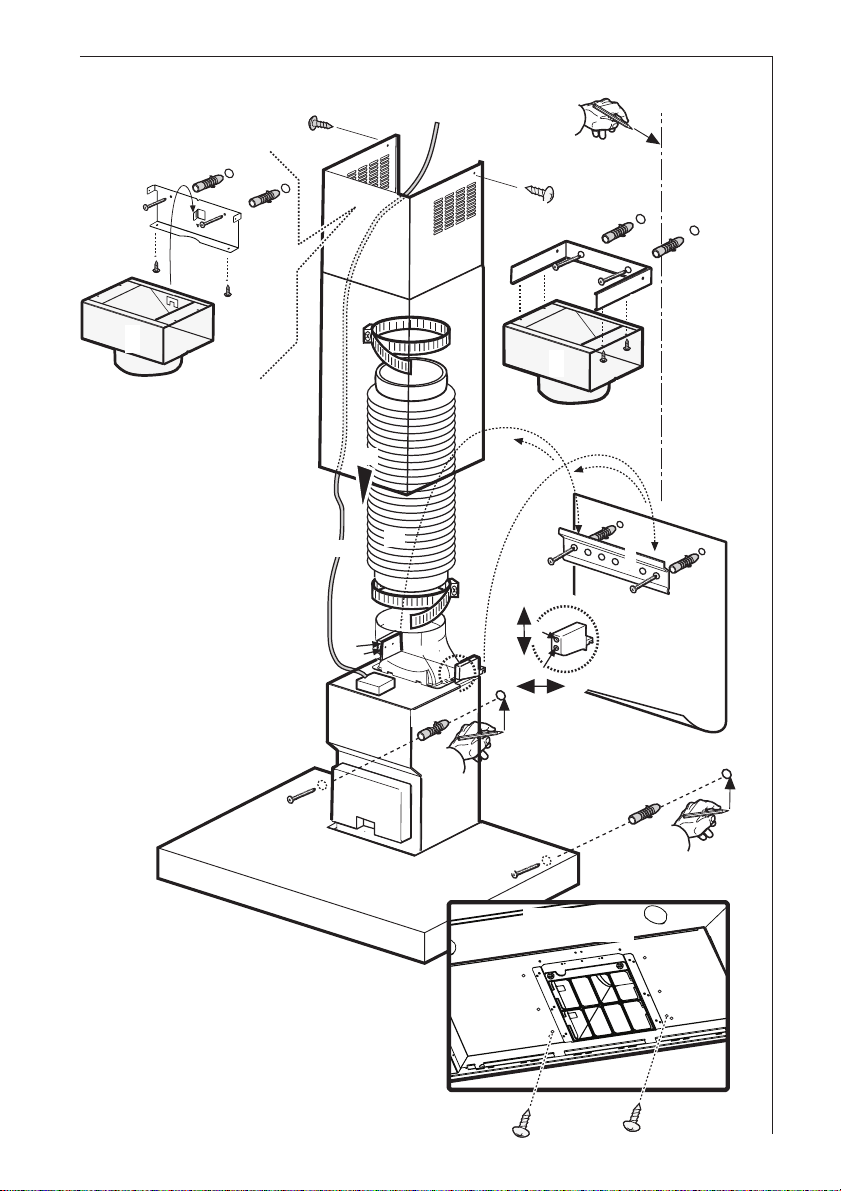
Wall unit mounting - Fig. 6
• Sign the wall with a center line, this will aid mounting procedure (1),
position the template so that the mid line printed on the template
matches with the center line previously signed, the lower side of the
template corresponds to the lower side of the hood once mounted
(2).
• Drill two holes Ø 8mm and fix the support bracket with two wall plugs
and screws (3). Hang the hood (4) and adjust its position (5-6).
• From the inside of the hood sign two points for definitive fixing (7).
• Remove the hood (8) and drill two holes Ø 8mm (9), fit two wall plugs
(10).
• Drill two holes Ø 8mm on the upper side close to the ceilling, fit two
wall plugs (11) (In case the hood is to be used in filter version,
mount the deflector F on the chimney support with four screws
2,9x6,5 (2 screws for hood model DD 8623)) and fix the chimney
support G with two screws (12).
• Hang the hood again (13) and fix it definitively with two screws (14).
• Fit an exhausting pipe (15) to connect the outlet hole A of the hood
to the outside (Extractor hood) or to the deflector F (Filter version).
• Make electrical connection (16).
• Fix the chimney first up (17a) to the chimney support (17b), then
slide the lower section of the chimney down into the proper housing
on top of the hood (18).
• Only for model DD 8623: Fix the lower section to the hood with two
screws 3 x 9 mm (19).
78
Page 19
17a
1
F
DD 8623
G
14
16
H
17a
17b
11
11
G
12
17b
F
4-13
18
15
B
6
5
10
8
6
5
9
7
4-13
8
3
10
2
9
7
Fig. 6
14
DD 8623
19
19
79
 Loading...