

Page 1

825 D / 8259 D
Extractor Hood
Installation and Operating Instructions
Page 2
Contents
Introduction 3
Extraction mode 3
Recirculation mode 4
Electrical connection for the UK 5
T echnical Details 6
Installation 7
Safety warnings 7
Installation 8
Hood Operation 11
Safety warnings for user 1 2
Maintenance and care 13
Metal grease filter 13
Opening the metal grease filter 1 3
Carbon filter 1 4
Changing the light bulb 1 5
Cleaning 16
Accessories 16
Something not working 17
Service & Spare Parts 18
Printed on recycled paper.
AEG – putting words into action.
2
Page 3
Introduction
Extraction mode
● The hood is supplied as an extractor unit and can also be used as a
filtered function by fitting activated carbon filters (available as an
accessory).
● You will need original AEG activated carbon filters for the filtered
function (see Accessories).
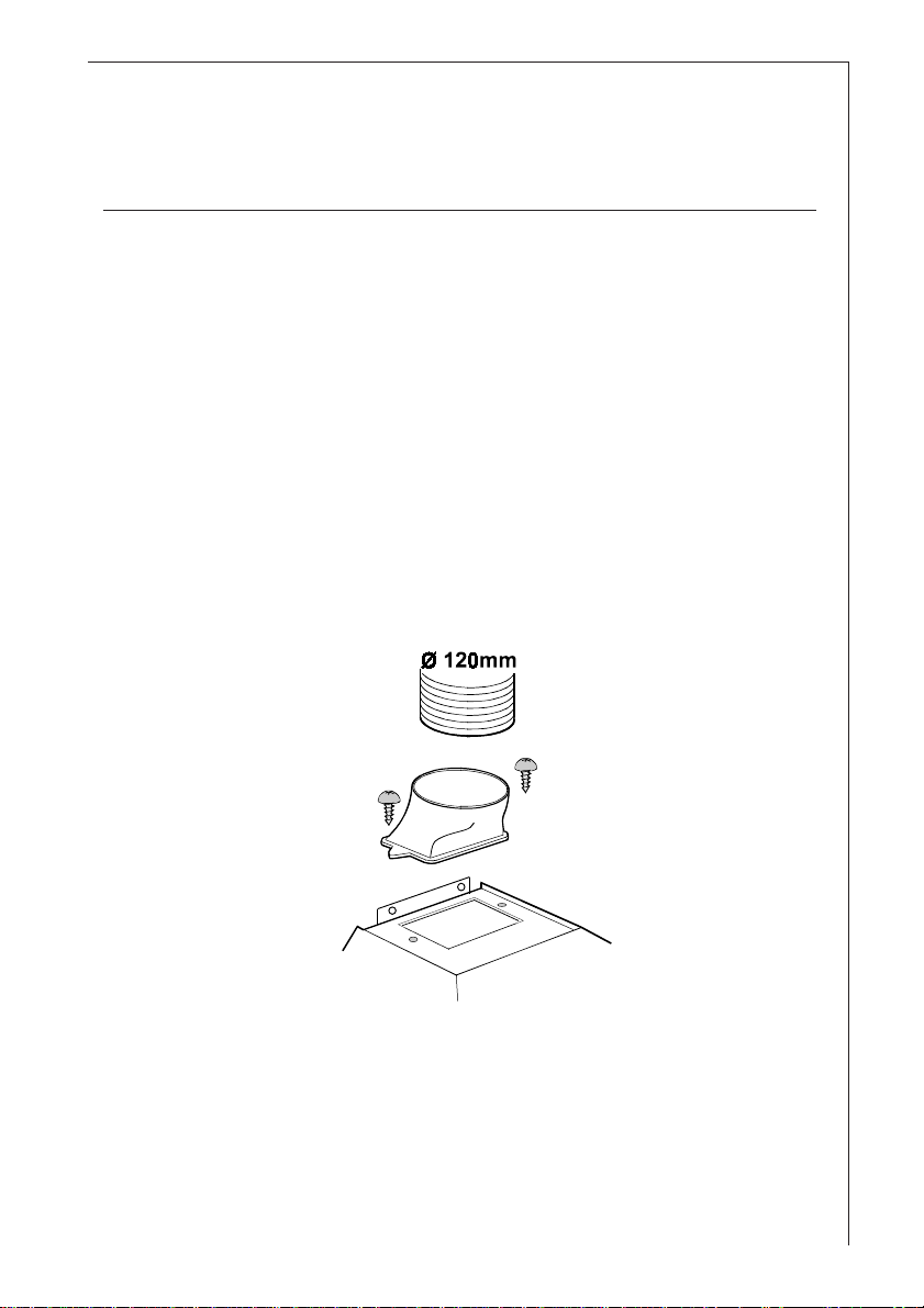
● The air is forced out through a hose fitted to the top of the hood
A. Fig. 1.
● The outlet hose must have a diameter of 120 mm (accessory) for
the extraction mode.
● Fit the connection ring above the hood with two screws then fir an
exhausting pipe long enough to reach the outside. Fig. 1.
A
Fig. 1
● If the cooking vapour is passed through an outside wall, you will
need an MKZ telescopic wall pipe (with intake and ventilation) ENr.: 610 899 004 (120 mm Ø) from our range of accessories.
3
Page 4
Recirculation mode
● The air is filtered through an activated carbon filter and passed
back into the kitchen through the top outlet duct grids.
● Y ou will need an original AEG KF 825 activated carbon filter for the
filtering function. (See Accessories).
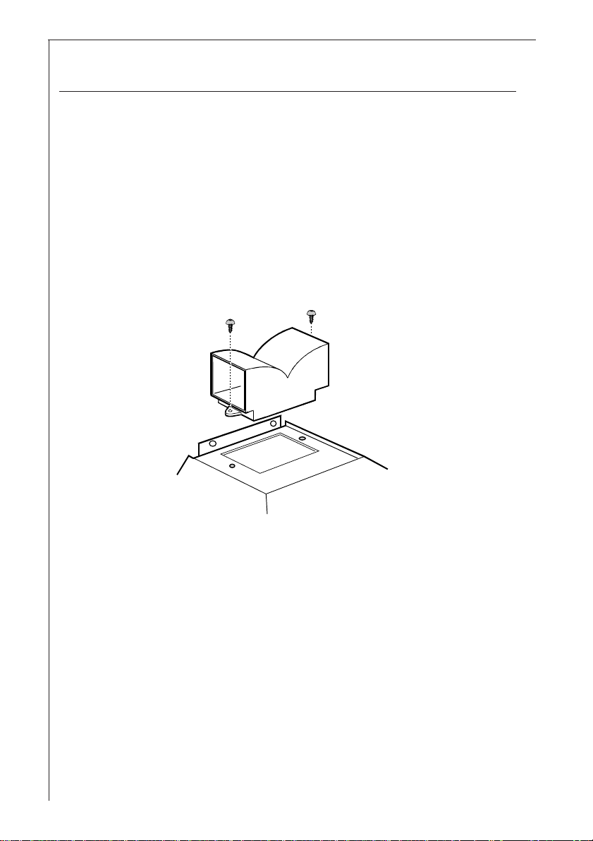
● Fix the deflector with two screws Ø3,5x6,5. Fig. 2.
Fig. 2
4
Page 5
Electrical connection for the UK
Appliances with 2 wires
WARNING: DOUBLE INSULATED - DO NOT EARTH
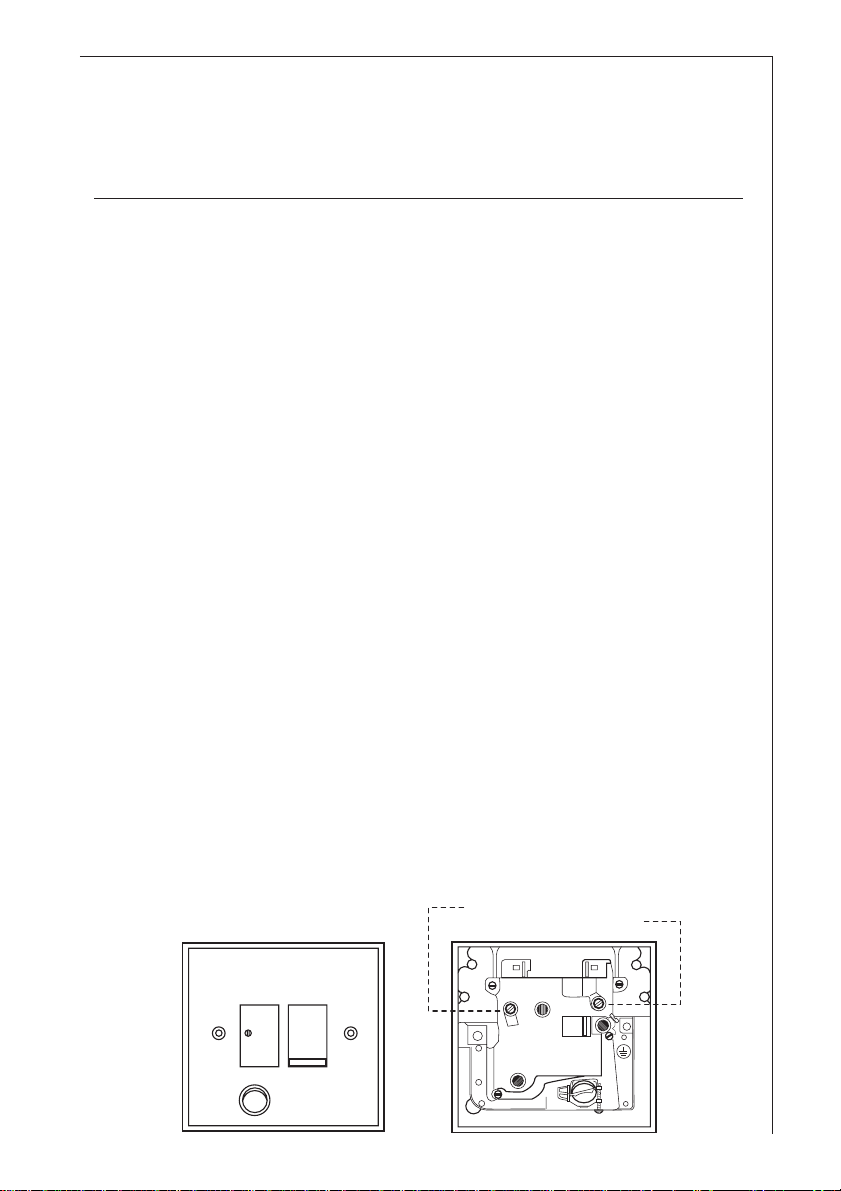
The appliance must be connected to fixed wiring with a double
pole switched fused spur outlet with or without pilot lamp.
We strongly recommend the appliance to be connected only by a
qualified electrician who is a member of the NICEIC who will comply with the IEE and any local regulations.
NOTE:
The terminology “DOUBLE POLE” means that both the live and the
neutral supplies are switched and disconnected at the same time.
The terminations labelled SUPPL Y are for the connection for the
internal house wiring and the terminations labelled LOAD are for
the appliance.
IMPORT ANT
The wires of the mains lead supplied with this appliance are
coloured in accordance with the following code:
Blue-Neutral
Brown-Live
As the colours of the flexible cord of this appliance may not
correspond with the coloured markings identifying the terminals in the plug, proceed as follows: The wire which is coloured brown must be connected to the terminal which is
marked with the letter L or coloured red.
The wire which is coloured blue must be connected to the
terminal which is marked with the letter N or coloured black.
FUSE
BLUE
(NEUTRAL)
SUPPLY
N
ON
N
LOAD
SUPPLY
DP 13A, 250V
BROWN
(LIVE)
L
LOAD
L
5
Page 6
T echnical Details
Dimensions (825 D):
Height x Width x Depht (in cm) 84-117 x 59,9 x 51.5
Dimensions (8259 D):
Height x Width x Depht (in cm) 84-117 x 89,9 x 51.5
Weight (825 D):
Net: 10,7 kg
Gross: 16,2 kg
Weight (8259 D):
Net: 13,1 kg
Gross: 19,6 kg
Maximum absorbed power: 250W
Motor absorption: 1 x 170 W
Lighting: 2 x 40 W
Length of the cable: 100 cm
Fan powers (speed), speed in compliance with DIN 44971
Extractor version:
1 179 m3/h
2 219 m3/h
3 336 m3/h
Filter version:
1 102 m3/h
2 150 m3/h
3 252 m3/h
Flange: 120 mm Ø
6
Page 7
Installation
Safety warnings for kitchen unit installer
● When used as an extractor unit, the hood must be fitted with a
120mm diameter hose.
● If the fumes must be forced out through the wall, you must obtain
a MKZ sizable wall exhaust pipe (with external exhaust and air
intake), E-Nr.- 610 899 004 (Ø 120 mm) which is one of our
optional parts.
● When installing the hood, make sure you respect the following minimum distance from the top edge of the cooking
hob/ring surfaces:
Electric hob 600 mm
Gas hob 650 mm
Electric cooker 685 mm
Gas cooker 787 mm
● The cooker hood must not be installed above a cooker with a
high level grill.
● The air outlet must not be connected to chimney flues or combustion gas ducts. The air outlet must under no circumstances be
connected to ventilation ducts for rooms in which fuel-burning
appliances are installed.
● It is advisable to apply for authorization from the relevant
controlling authority when connecting the outlet to an unused
chimney flue or combustion gas duct.
The air outlet installation must comply with the regulations laid
down by the relevant authorities.
● When the unit is used in its extractor version, a sufficiently large
ventilation hole must be provided, with dimensions that are
approximately the same as the outlet hole.
● National and regional building regulations impose a number of
restrictions on using hoods and fuel-burning appliances connected
to a chimney , such as coal or oil room-heaters and gas fires, in the
same room.
7
Page 8

● Regulations on fuel-burning systems specify a maximum
depression of 0.04 bar in such rooms.
● Hoods can only be used safely with appliances connected to a
chimney if the room and/or flat (air/environment combination) is
ventilated from outside using a suitable ventilation hole approximately 500-600 cm2 to avoid the possibility of a depression being
created during operation of the hood.
If you have any doubts, contact the relevant controlling authority
or building inspector’s office.
● Since the rule for rooms with fuel burning appliances is “outlet hole
of the same size as the ventilation hole”, a hole of 500-600 cm2,
which is to say a larger hole, could reduce the performance of the
extractor hood.
● If the hood is used in its filtering function, it will operate simply and
safely in the above conditions without the need for any of the
aforementioned measures.
● When the hood is used in its extractor function, the following rules
must be followed to obtain optimal operation:
— short and straight outlet hose
— keep bends in outlet hose to a minimum
— never install the hoses with an acute angle, they must
always follow a gentle curve only
— keep the hose as large as possible (120 mm Ø min.).
● Failure to observe these basic rules will drastically reduce the
performance and increase the noise levels of the extractor
hood.
● Where flexible ducting is fitted the length should be no more
than:
— 3 metres with one 90° bend
— 2 metres with two 90° bends.
Bends of more than 90° will reduce the efficiency of the hood
and reduce the air flow.
8
Page 9
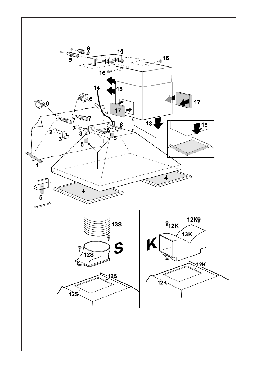
Installation - Fig. 3
●●
● Put the template onto the wall (1) and drill two Ø12mm holes
●●
(2).
●●
● Fit two hooks (3) on the drilled holes.
●●
●●
● Hang the hood on the hooks and adjust the position of the
●●
hood using the two screws on the bottom of the hooks (5).
●●
● Remove the metal filters (4) and mark two points (6).
●●
Remove the hood and drill two Ø8mm holes on the marked
points.
Fit two Ø8mm wall dowels (7), Hang again the hood and fix
the hood definitively with two screws 5X45 (8).
●●
● Fix the chimney support (10) with two screws 5 x 45 mm (9)
●●
and two wall dowels (11) on the wall close to the ceiling.
●●
● For exhausting version: Fit the connection ring (S) on the
●●
top of the hood with two screws Ø 3,5 x 6,5 mm (12S) then
fit an exhausting pipe long enough to reach the outside
(13S).
For recycling version: Fix definitively the deflector (13K)
on the top of the hood with two screws Ø 3,5 x 6,5 mm
(12K).
●●
● Prepare the electric connection (14) (see relative chapter).
●●
●●
● Fit the chimney (15) and fix it on the chimney support with
●●
two screws 3,0 x 9 mm (16).
The lower part of the chimney must be slided down and
inserted on the housing on the upper part of the hood (18).
●●
● Fit the two grids (17) on both sides of the chimney.
●●
9
Page 10
10
Fig. 3
Page 11
Hood Operation
● The hood is fitted with a variable speed motor . The most effective
use of the hood is obtained by switching it on a few minutes before
you start cooking and leaving it on for approximately 15 minutes
after you have finished, thus ensuring all cooking odours are
eliminated. The control switches are located on the unit’s front
panel:
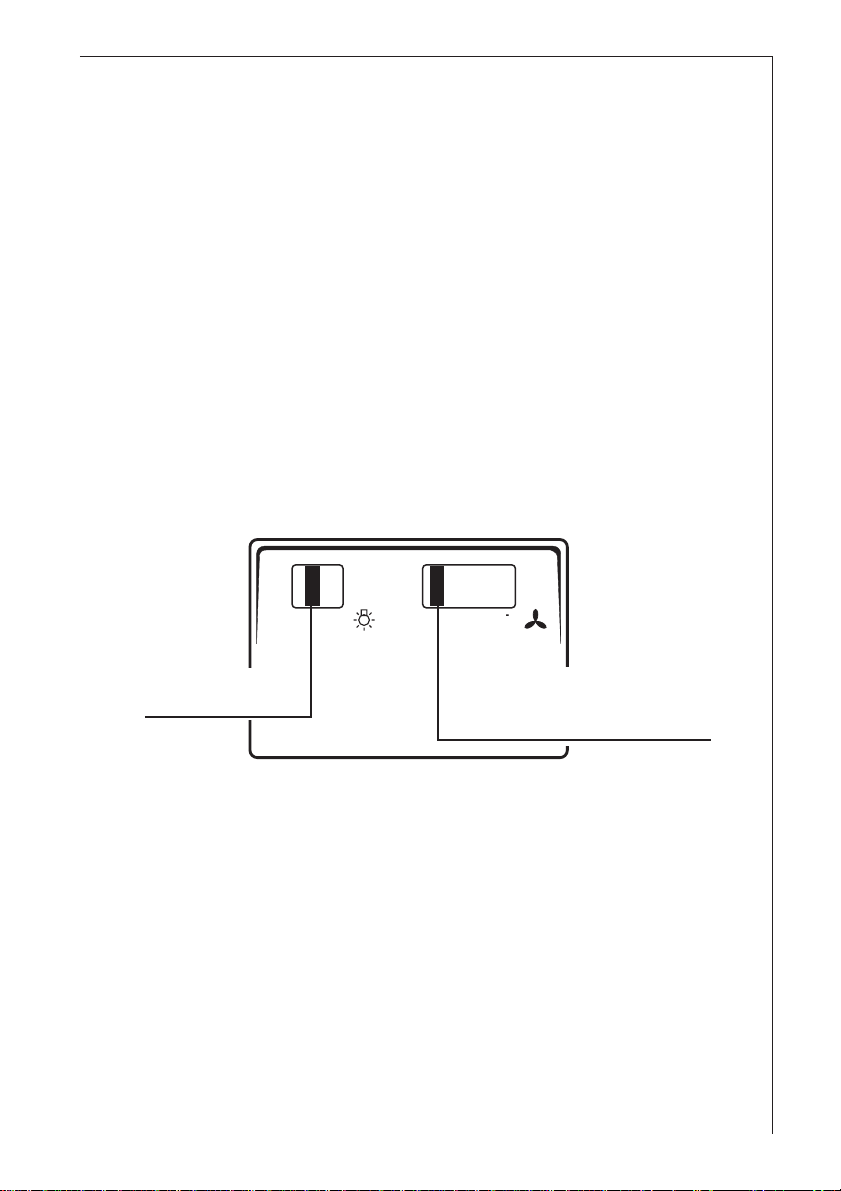
● the light switch switches the hood lamp on and off;
● the motor switch switches the extractor motor on and off,
enabling you to select one of the three different speeds.
OI O123i
Light switch
ON/OFF
O - OFF
I - ON
Motor power
adjustable to 3
positions
O - OFF
I - LOW
2 - MEDIUM
3 - HIGH
11
Page 12
Safety warnings for user
● Never leave a cooking hob or ring on without a pot or pan
on top of it, to avoid the possibility of excess heat damaging
the unit. Gas, oil or coal cooker flames in particular should
never be left uncovered.
● Special care should be taken when using deep fat fryers since
the oil in them can overheat and burst into flames.
● The risk of a fat fire increases when using dirty oil.
● It is extremely important to note that overheating can cause
a fire.
● Never carry out any flambé cooking under the hood.
● Always disconnect the unit from the power supply
before carrying out any work on the hood, including
replacing the light bulb (take the cartridge fuse out of the
fuse holder or switch off the automatic circuit breaker).
12
● It is very important to clean the hood and replace the
filter at the recommended intervals. Failure to do so
could cause grease deposits to build up, causing a fire
hazard.
Page 13
Maintenance and care
● The hood must always be disconnected from the mains
power supply before beginning any maintenance work.
Metal grease filter
● The purpose of the grease filters is to aspirate grease particles
which form during cooking and it must always be used, either in
extraction or recirculation mode.
Attention: the metal grease filters must be removed and washed,
either by hand or in the dishwasher , every four weeks.
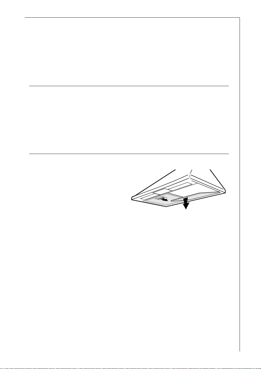
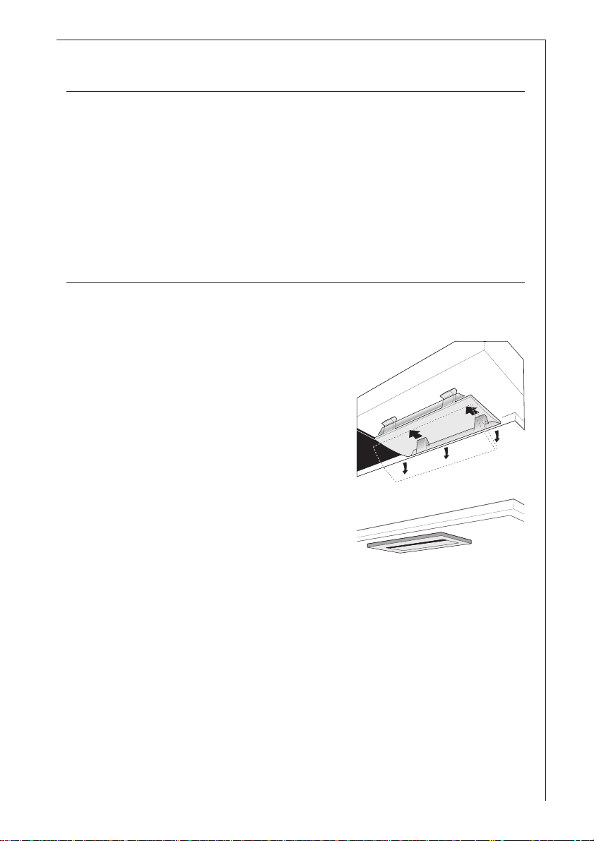
Open the metal grease filter
● Push the filters towards the
back of the unit and then pull it
down and out.Fig. 4.
Hand washing
Soak grease filters for about one hour in hot water with a greaseloosening cleaner, then rinse of f thoroughly with hot water. Repeat
the process if necessary . Refit the grease filters when it are dry.
Dishwasher
Place the grease filters in a dishwasher. Select the most intensive
washing programme and highest temperature, at least 65°C.
Repeat the process if necessary . Refit the grease filters when they
are dry .
When washing the metal grease filter in the dishwasher a slight
discoloration of the filter can occur, this does not have any impact
on its performance.
● Clean the inner housing using a hot detergent solution only (never
use caustic detergents, abrasive powders or brushes).
Fig. 4
13
Page 14
Carbon filter
● The activated carbon filter should only be used if you want to use
the hood in the recirculation.
● T o do this you will need an original AEG activated carbon filter (see
special accessories).
● This filter cannot be cleaned or reused.
● As a general rule, the activated carbon filter should be
replaced once every four months.
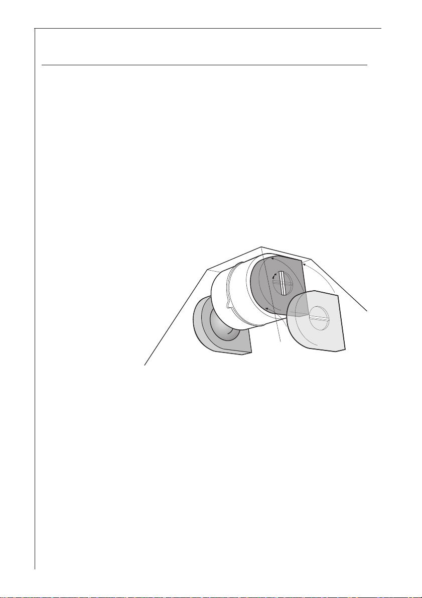
● Mounting — Fig. 5
Fit one carbon filter on the left and one on the right so to cover
the plastic grids that protect the fan wheel, then turn clockwise the
central handle of the carbon filter.
Fig. 5
● T o remove proceed in reverse order.
● Always specify the hood model code number and serial number
when ordering replacement filters. This information is shown on
the rating plate located on the inside of the unit.
● The activated carbon filter can be ordered from the AEG Service
Force.
14
Page 15
Warning
● Failure to observe the instructions on maintenance and cleaning,
and changing the filters will cause a fire hazard. Y ou are therefore
strongly recommended to follow these instructions.
● The manufacturer declines all responsibility for any damage to the
motor or any other damage linked to inappropriate maintenance
or failure to observe the above safety recommendations.
Changing the light bulb
● Disconnect the unit from the
mains power supply .
● Remove the lamp cover.
● Replace the old light bulb with a new
light bulb (40 W
max.).
● Fit the lamp cover on its seat.
● If the light does not come on, make
sure the bulb has been screwed in
correctly before contacting AEG
Service Force..
Fig. 6
15
Page 16

Cleaning
● Warning: always disconnect the hood from the mains power supply
before cleaning it.
Never insert pointed objects in the motor’s protective grid.
● Wash the outside surfaces using a mild detergent solution. Never
use caustic detergents or abrasive brushes or powders.
● Only ever clean the switch panel and filter grille using a damp cloth
and delicate detergents.
● It is extremely important to clean the unit and change the filters at
the recommended intervals. Failure to do so will cause grease
deposits to build up that could constitute a fire hazard.
Accessories
MKZ telescopic wall pipe E-Nr. 610 899 004
outlet hose ABS120 - 120 mm Ø 942 118 611
Carbon filter KFF 942 118 627
16
Page 17
Something not working
If your cooker hood fails to work properly please carry out the following checks.
Sympton Solution
The cooker hood will not start... The hood is connected to the
electricity supply .
Check that the fan speed control is
set to 1, 2 or 3.
The cooker hood is not working The fan speed is set high enough
effectively... for the task.
The grease filter is clean.
The kitchen is adequately vented to
allow the entry of fresh air.
If set up for recirculation, check that
the charcoal filter is still effective.
If set up for extraction, check that
the ducting and outlets are not
blocked.
The cooker hood has switched off The safety cut-out service has been
during operation... tripped.
Turn off the hob and then wait for the
device to reset.
If after all these checks, the problem persists, contact your local Service Force
Centre, quoting the model and serial number.
Please note that it will be necessary to provide proof of purchase for any inguarantee service calls.
In-guarantee customers should ensure that the above checks have been
made as the engineer will make a charge if the fault is not a mechanical or
electrical breakdown.
17
Page 18

Service & Spare Parts
If you require a service engineer or wish to purchase spare parts,
contact your local AEG Service Centre, by telephoning:
0990 929929
Help us to help you
Please determine your type of enquiry before telephoning. When you
contact us we need to know.
1. Y our name, address and post code
2. Y our telephone number
3. Clear and concise details of the fault.
4. The model, serial number (E-Nr) and the manufacturing
number (F-Nr) (This information can be found on the
rating plate).
5. Date of purchase.
Customer Care
For general enquiries regarding your AEG appliance, or further information
on AEG products please contact our customer care department.
Customer Care Department
AEG Domestic Appliances Limited
PO Box 47
Newbury
Berkshire RG14 5XL
T el: 01635 572700
Fax: 01635 42970
18
Page 19
19
Page 20

AEG Hausgeräte AG
Postfach 1036
D-90327 Nürnberg
© Copyright by AEG
LI03XA
Page 21

documentation manual, user maintenance, brochure, user reference, pdf manual
This file has been downloaded from:
User Manual and User Guide for many equipments like mobile phones, photo cameras, monther board, monitors, software, tv, dvd, and othes..
Manual users, user manuals, user guide manual, owners manual, instruction manual, manual owner, manual owner's, manual guide,
manual operation, operating manual, user's manual, operating instructions, manual operators, manual operator, manual product,
 Loading...