

Page 1
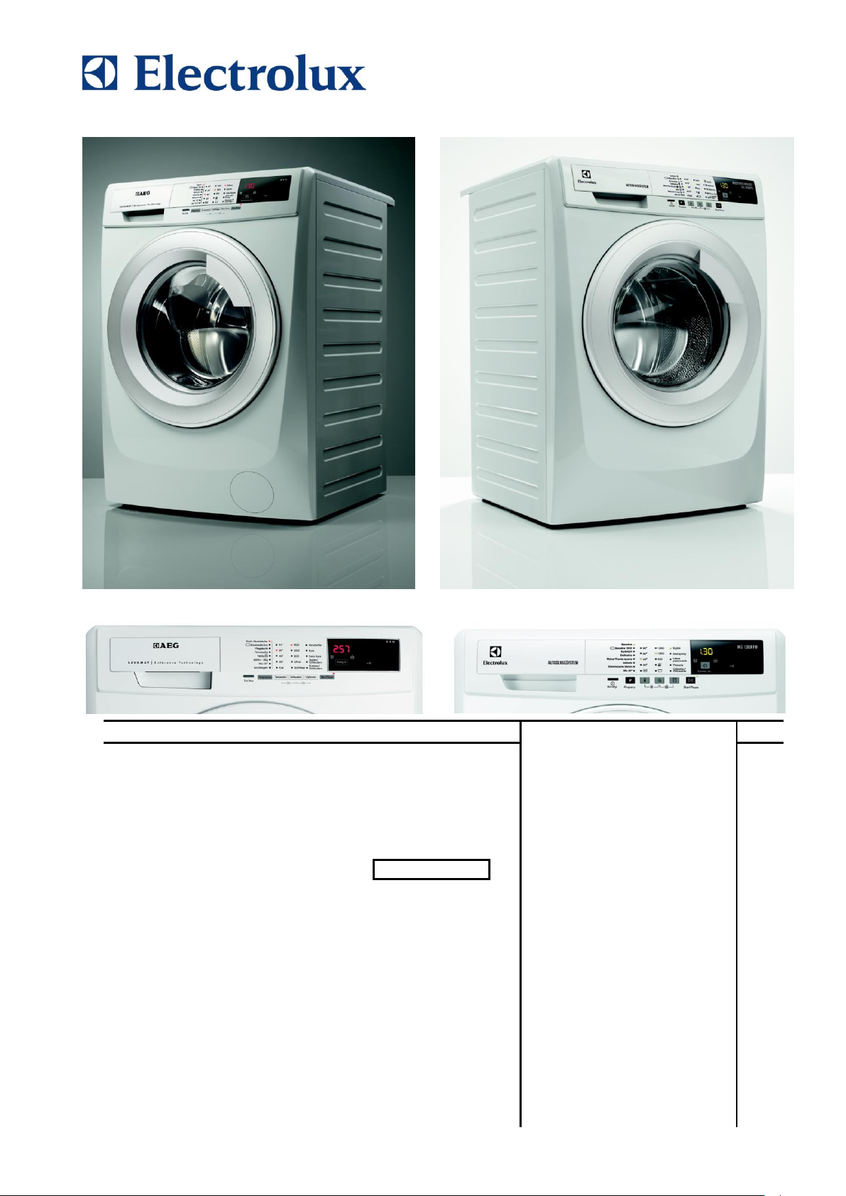
SERVICE MANUAL
Front-Loading Washing
Machines
with electronic control
system
EWX13611
Technical and functional
characteristics
PILOT 2
Styling
Core (P3.0)
P49
ELECTROLUX HOME PRODUCTS
Customer Care - EMEA
Training and Operations Support
Technical Support
Publication
number
599 78 10-24
Edition: 12/2014 - Rev. 01
EN
CORE (P3.0)
CORE (P3.0)
WASHING
Page 2

Technical Support - MDM 2/84 599 78 10-24 Rev.01
Page 3

INDEX
1 PURPOSE OF THIS MANUAL ............................................................................................................................. 5
1.1 Low consumption mode ................................................................................................................................. 5
1.1.1 With universal motor ............................................................................................................................... 5
2 WARNINGS .......................................................................................................................................................... 6
3 NORMAL ............................................................................................................................................................... 7
3.1 EWX13611 General characteristics ............................................................................................................... 7
3.2 Control panel.................................................................................................................................................. 8
3.2.1 Display board .......................................................................................................................................... 8
3.2.2 Control panel configuration..................................................................................................................... 9
3.2.2.1 Programme configuration ................................................................................................................ 9
3.2.2.2 Sensors – LEDs .............................................................................................................................. 9
3.2.2.3 Buttons – Sensors – LEDs ............................................................................................................ 10
3.2.2.4 Display ........................................................................................................................................... 13
3.2.2.5 Buzzer ........................................................................................................................................... 14
4 “DEMO” MODE ................................................................................................................................................... 16
4.1 Access to DEMO settings ............................................................................................................................ 16
4.2 Exiting DEMO mode .................................................................................................................................... 16
5 DIAGNOSTICS SYSTEM ................................................................................................................................... 17
5.1 Accessing diagnostics ................................................................................................................................. 17
5.2 Quitting the diagnostics system ................................................................................................................... 17
5.3 Phases of the diagnostics test ..................................................................................................................... 18
6 ALARMS ............................................................................................................................................................. 20
6.1 Displaying user alarms ................................................................................................................................ 20
6.2 Alarm reading/display .................................................................................................................................. 21
6.2.1 Displaying the alarm ............................................................................................................................. 21
6.2.2 Rapid reading of alarms ....................................................................................................................... 21
6.2.3 Deleting the last alarm .......................................................................................................................... 21
7 OPERATING TIME COUNTER .......................................................................................................................... 22
7.1 Reading the operating time .......................................................................................................................... 22
7.2 Display of total operating time ..................................................................................................................... 22
8 OPTIONS ............................................................................................................................................................ 23
8.1 Compatibility between options ..................................................................................................................... 23
8.2 Description of options .................................................................................................................................. 24
9 TECHNICAL CHARACTERISTICS..................................................................................................................... 25
9.1 Construction characteristics (with drain filter removable from the outside) ................................................. 25
9.2 Construction characteristics (with drain filter not removable from the outside) ........................................... 26
9.3 Detergent dispenser .................................................................................................................................... 27
9.4 Detergent drawer ......................................................................................................................................... 28
9.5 Washing unit ................................................................................................................................................ 29
9.6 Water circuit ................................................................................................................................................. 30
9.6.1 Traditional OKO version drain circuit (with drain filter removable from the outside) ............................ 30
9.6.2 OKO/IDB version drain circuit (with drain filter not removable from the outside) ................................ 30
9.7 Electronic control ......................................................................................................................................... 31
9.7.1 Programming/Updating the main circuit board ..................................................................................... 31
9.7.2 Electrical features ................................................................................................................................. 32
10 ELECTRICAL COMPONENTS ....................................................................................................................... 33
10.1 Noise filter ................................................................................................................................................ 33
10.1.1 General characteristics ......................................................................................................................... 33
10.2 Display board ........................................................................................................................................... 33
10.3 Drainage pump ......................................................................................................................................... 34
10.3.1 General characteristics ......................................................................................................................... 34
10.4 Heating element ....................................................................................................................................... 35
10.4.1 General characteristics ......................................................................................................................... 35
10.5 Temperature probe .................................................................................................................................. 36
10.5.1 General characteristics ......................................................................................................................... 36
10.6 Analogue pressure switch ........................................................................................................................ 37
10.6.1 General characteristics ......................................................................................................................... 37
10.7 Door safety interlock PTO (Pull To Open) ............................................................................................... 38
10.7.1 General characteristics ......................................................................................................................... 38
10.7.2 Operating principle ............................................................................................................................... 38
10.7.2.1 Mechanical operation .................................................................................................................... 39
10.7.3 Manual opening of the appliance door: ................................................................................................ 40
10.8 Universal motor ........................................................................................................................................ 41
10.8.1 General characteristics ......................................................................................................................... 41
Technical Support - MDM 3/84 599 78 10-24 Rev.01
Page 4

10.8.2 Operating principle ............................................................................................................................... 41
10.8.2.1 Motor speed control....................................................................................................................... 41
10.8.2.2 Direction of rotation of the motor ................................................................................................... 42
10.8.2.3 Tachometric generator .................................................................................................................. 42
10.8.3 Power supply to motor .......................................................................................................................... 43
10.9 Anti-foam control system .......................................................................................................................... 43
10.10 Solenoid valves ........................................................................................................................................ 44
10.10.1 General characteristics ..................................................................................................................... 44
10.10.2 Operating principle ............................................................................................................................ 44
10.10.3 Mechanical jamming of the solenoid valve ....................................................................................... 44
10.10.4 Low water pressure ........................................................................................................................... 44
11 ALARM SUMMARY TABLE ............................................................................................................................ 45
12 DIAGRAMS ..................................................................................................................................................... 48
12.1 EWX13611 Operating Circuit Diagram .................................................................................................... 48
12.2 EWX13611 Operating circuit diagram key ............................................................................................... 49
13 ACCESS .......................................................................................................................................................... 50
13.1 Worktop .................................................................................................................................................... 50
13.2 From the worktop, you can access .......................................................................................................... 50
13.2.1 Main board ............................................................................................................................................ 50
13.2.2 Solenoid valve ...................................................................................................................................... 53
13.2.3 Display board assembly ....................................................................................................................... 53
13.2.4 Control panel ........................................................................................................................................ 55
13.2.5 Analogue pressure switch .................................................................................................................... 58
13.2.6 Detergent dispenser ............................................................................................................................. 59
13.2.7 Upper counterweight ............................................................................................................................ 60
13.3 Accessing the front part ........................................................................................................................... 61
13.3.1 Door hinge - Door ................................................................................................................................. 61
13.3.2 Door safety interlock ............................................................................................................................. 61
13.3.3 Blade ..................................................................................................................................................... 64
13.3.4 Front panel ........................................................................................................................................... 66
13.4 From the front panel, you can access ...................................................................................................... 67
13.4.1 For appliances with drain filter removable from the outside ................................................................. 67
13.4.1.1 Front counterweight....................................................................................................................... 67
13.4.1.2 Bellow seal .................................................................................................................................... 67
13.4.1.3 Welded tub assembly .................................................................................................................... 68
13.4.1.4 Tub suspension springs ................................................................................................................ 68
13.4.1.5 Drain water circuit .......................................................................................................................... 69
13.4.1.5.1 Filter body ................................................................................................................................ 69
13.4.1.5.2 Drain pump .............................................................................................................................. 70
13.4.2 For appliances with drain filter not removable from the outside ........................................................... 71
13.4.2.1 Front counterweight....................................................................................................................... 71
13.4.2.2 Bellow seal .................................................................................................................................... 71
13.4.2.3 Welded tub assembly .................................................................................................................... 71
13.4.3 Tub suspension springs ........................................................................................................................ 71
13.5 Accessing the rear part ............................................................................................................................ 72
13.5.1 Back panel ............................................................................................................................................ 72
13.6 From the back panel, you can access ..................................................................................................... 72
13.6.1 Belt ........................................................................................................................................................ 72
13.6.2 Plastic pulley ( 273 mm) .................................................................................................................... 73
13.6.3 Motor ..................................................................................................................................................... 73
13.6.4 Heating ................................................................................................................................................. 73
13.7 From the base of the appliance, you can access .................................................................................... 74
13.7.1 For appliances with drain filter removable from the outside ................................................................. 74
13.7.1.1 Drain water circuit .......................................................................................................................... 74
13.7.1.1.1 Drainage pump ........................................................................................................................ 74
13.7.1.1.2 Tub drain pipe .......................................................................................................................... 74
13.7.2 For appliances with drain filter not removable from the outside ........................................................... 75
13.7.2.1 Drain water circuit .......................................................................................................................... 75
13.7.2.1.1 Drainage pump ........................................................................................................................ 75
13.7.2.1.2 Drain filter ................................................................................................................................ 76
13.7.2.1.3 IDB (Integrated Drain Body) .................................................................................................... 76
13.7.3 Pressure chamber (both versions) ....................................................................................................... 79
13.7.4 Shock absorbers (both versions) .......................................................................................................... 81
13.7.5 Shock absorber pin (both versions) ...................................................................................................... 81
13.7.6 Main drain pipe ..................................................................................................................................... 82
Technical Support - MDM 4/84 599 78 10-24 Rev.01
Page 5

1 PURPOSE OF THIS MANUAL
The purpose of this manual is to provide service engineers who are already familiar with the repair procedures for
traditional washing machines with information regarding washing machines fitted with the EWX13611 (P3.0)
electronic control system
Previous platforms (electronic/mechanical) used a safety pressure switch that checked the minimum water level in
the tub, below which the supply to the heating element was interrupted.
The current electronic appliances manufactured use a heating element with thermal fuses (inside its branches) as
safety, which interrupt if the water level drops below the minimum level permitted.
The incorporated NTC probe contacts have a 2.5 mm pitch.
The manual deals with the following topics:
General characteristics
Control panel and compatibility between washing programmes and options
Settings: Demo, Diagnostics
Alarms
Technical and functional characteristics
Access
1.1 Low consumption mode
In order to reduce electricity waste when the cycle is not running, the appliances on this platform are designed to
enter consumption reduction mode.
1.1.1 With universal motor
“Stand-Off” mode
When the appliance is switched off at the ON/OFF button, it is in the “Stand-Off” or “virtual” off status. The LEDs
and the LCD screen are turned off and the buttons are disabled, although the main circuit board and certain
electrical components are electrically powered.
You have to unplug the appliance to cut off the power supply
“Auto-off” mode
If, after 5 minutes, during the programme selecting phase or after the end of the cycle, the appliance receives no
further instructions, it is automatically turned off (for energy savings in conformity with the standards on energy
consumption).
All the settings are stored so that when the appliance is turned back on, the programme is ready or if the auto-off
mode was triggered after the end of the cycle, the user can see that the cycle ended normally, and can restart it if
necessary.
You have to unplug the appliance to cut off the power supply
If an alarm goes off when a wash programme is running, the automatic turn off is disabled showing the alarm.
Technical Support - MDM 5/84 599 78 10-24 Rev.01
Page 6
2 WARNINGS
Any work on electrical appliances must only be carried out by qualified personnel.
Before carrying out work on the appliance, use suitable instruments to check that
the power supply system in the house is fully efficient. For example: refer to the
indications provided/illustrated in the <<metratester>> course at the address
(http://electrolux.edvantage.net) on the Electrolux Learning Gateway portal.
On completing operations, check that the appliance has been restored to the same
state of safety as when it came off the assembly line.
If the circuit board has to be handled/replaced, use the ESD kit
(Code 405 50 63-95/4) to avoid static electricity from damaging the circuit board, see
S.B. No. 599 72 08-09 or consult the course <<Electrostatic charges>> at the address
(http://electrolux.edvantage.net) on the Electrolux Learning Gateway portal.
This platform is not fitted with an ON/OFF switch. Before you access internal
components, take the plug out of the socket to cut the power supply.
Make resistance measurements, rather than direct voltage and current
measurements
Warning the sensors located in the display board could be at a potential of
220 Volts.
When replacing the heating element, replace it with one that
has the same characteristics (2 thermal fuses) in order not to
compromise the safety of the appliance. It is strictly forbidden
to remove/switch the NTC sensors between heating elements.
Always empty the appliance of all the water before laying it on
its side (see the relevant paragraph).
Never place the appliance on its right side (electronic control system side): some of
the water in the detergent dispenser could leak onto the electrical/electronic
components and cause these to burn.
When replacing components, please refer to the code shown in the list of spare
parts relating to the appliance.
Do not place any kind of container under the appliance to catch any drips of water.
Make sure you wear gloves, because parts of the cabinet are sharp
Technical Support - MDM 6/84 599 78 10-24 Rev.01
Page 7
3 NORMAL
No. of buttons
maximum 1
No. of touch-sensitive keys
maximum 6 (5 options + start/pause)
No. LEDs
maximum 24 yellow + 1 red LED + Digit (made up of 22 LEDs)
Power supply voltage
220/240 V
50/60 Hz (configurable)
Washing type
Traditional with “Eco-ball” sphere
Rinsing system
Traditional with “Eco-ball” sphere
Motor
Collector, with tachometric generator (Universal)
spin speed
1,000 1,400 rpm
Anti-unbalancing system
AGS
Cold water fill
1 solenoid valve with 1 inlet - 2 outlets
Detergent dispenser
2 compartments: wash, conditioners
Control of water level in the tub
Electronic/analogue pressure switch
Door safety interlock
Instant “Pull To Open”
Heating element heat output
1,750 W with thermal fuses incorporated
Temperature check
NTC probe incorporated in the heating element
Buzzer
Traditional incorporated in the PCB
3.1 EWX13611 General characteristics
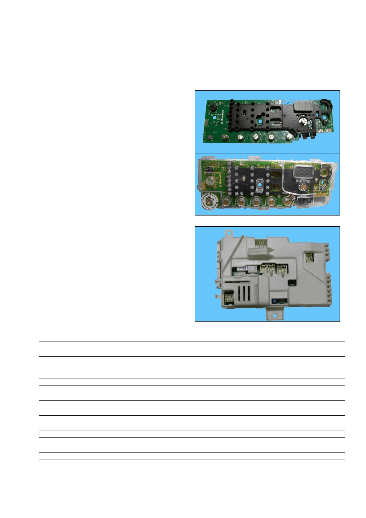
The electronic control system consists of two circuit boards.
In the event of problems with the touch sensors (difficulty selecting/adjusting them), clean and dry the display and
do not wear gloves when setting the chosen programme.
The control/display board, which is inserted in a
plastic container fixed to the control panel (the
figure shows: the display board and the display
board assembly).
Main board, positioned at the rear of the
appliance. It powers the electrical components
and receives commands from the display board.
Technical Support - MDM 7/84 599 78 10-24 Rev.01
Page 8
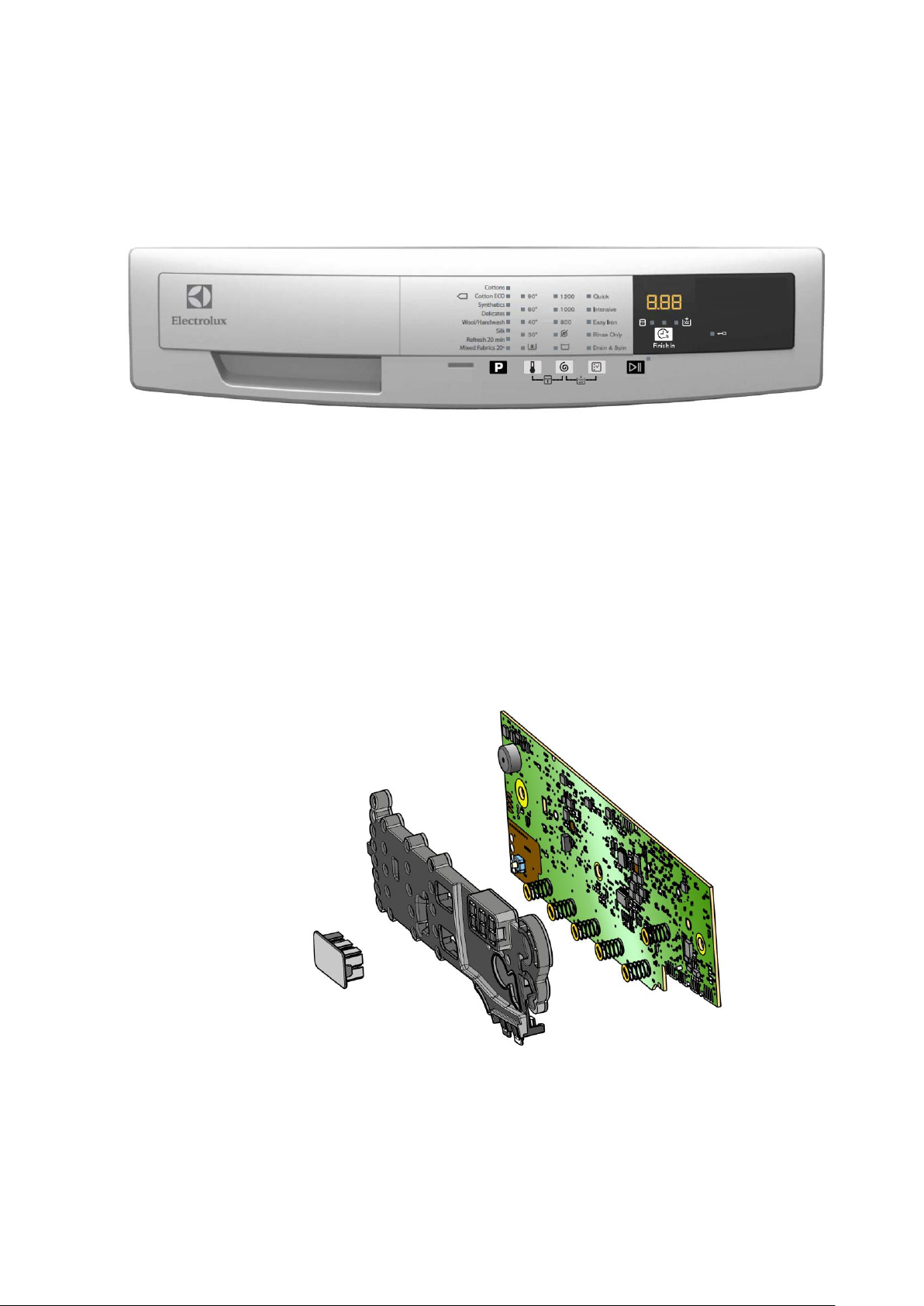
3.2 Control panel
1 2 3
Max. 1 Button
Max. 6 sensors
25 LEDs
1 LCD
3.2.1 Display board
Display board assembly, exploded view
1 Display board
2 Light divider
3 Light diffuser
Technical Support - MDM 8/84 599 78 10-24 Rev.01
Page 9
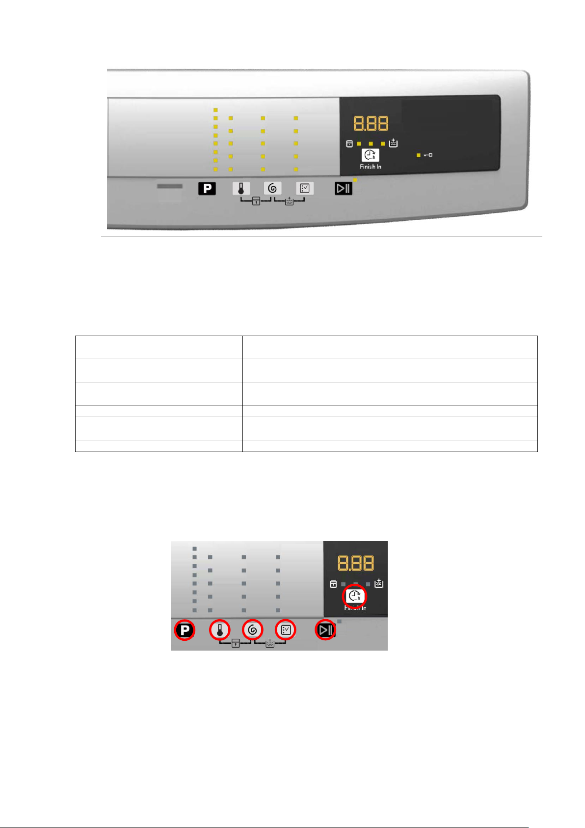
3.2.2 Control panel configuration
Types of fabric
Cotton/linen, Synthetic fabrics, Delicates, Wool, Hand-wash,
Shoes, Jeans, Duvet, Silk.
Special programmes
Cotton/linen + pre-wash, Soak, Miniprogramme, Easy-Iron,
Conditioner, Rinse, Drain, Spin, Economy.
Temperature
Normal, Minimum, Maximum: the initial temperature is the one
proposed for the washing programme.
Spin
Normal, Minimum, Maximum.
Options (Normal/Possible)
Rinse Hold, Pre-wash, Extra rinse, Easy-Iron, Economy (energy
label), Normal, Super quick, Reduced spin speed, No spin.
Programme phases
Pre-wash, Wash, Rinses, Spin, Delayed start.
L1
L28
L2
L3
L4
L5
L6
L7
L8
L9
L10
L11
L12
L13
L14
L15
L16
L17
L18
L19
L20
L21
L22
L23
L24
L25
L26
L27
The washing programmes and the functions and the various touch sensors vary according to the model,
since these are determined by the configuration of the appliance.
3.2.2.1 Programme configuration
The table below lists the parameters that can be used to define the washing programmes.
3.2.2.2 Sensors – LEDs
The function of each touch sensor is defined via the configuration of the appliance (the data and images are for
guidance only).
The touch sensors are positioned under the silk-screen printed symbols on the control panel (circled here in red)
A light touch on the center of the symbol is enough to activate/deactivate the function linked to the sensor with the
switching on/off of the relative Led confirming that the enabling/disabling has taken place.
At the same time as the enabling/disabling of options, the cycle duration time is updated via the digits (styling P3.0
only).
You need to keep your finger pressed down for a longer period of time with the Start/Pause sensor to confirm both
the cycle's start and pause, in order to avoid unwanted starts or accidental pauses.
Technical Support - MDM 9/84 599 78 10-24 Rev.01
Page 10
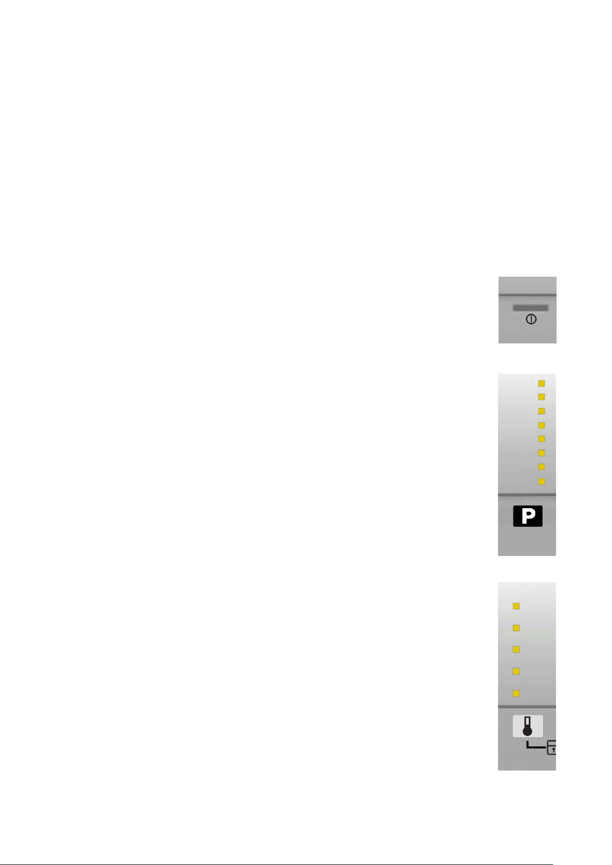
Every time you touch a sensor, you need to lift your finger up by a centimeter and half a second needs to elapse
P1
L9
L13
S2
L1
L8
S1
before touching it again, otherwise the electronic system does not recognize that the sensor has been touched for
a second time.
The sensors used for adjusting the: Temperature, Spin, delayed Start and Time Manager have a continued
variation of values as long as your finger is in contact with the sensor.
3.2.2.3 Buttons – Sensors – LEDs
Button no. 1: ON/OFF - ON
Press it to turn the appliance on, at the same time the buzzer will sound a tone (if enabled), the LEDs of the first
four touch sensors (S1÷S4) will light up from the bottom up, then the LEDs relating to the following will stay on: the
main programme, the recommended spin speed and temperature.
The operation of the ON/OFF depends on the configuration of the main circuit board.
Press the ON/OFF button to cancel the chosen programme.
To switch the appliance off, hold down the button for 1 second,
the buzzer will at the same time sound a tone (if enabled), all the LEDs will switch off, all
the options selected and any programme that is running will be cancelled.
Sensor no. 1: PROGRAMMES
The programmes are associated with the second sensor, combined with eight LEDs (L1÷L8).
As soon as the appliance is switched on, the first LED at the top corresponding to the main
programme lights up.
To the left of each LED, there is a description of the programme and each time the sensor is
touched, the LED underneath it lights up, so the programme selection occurs from the top
down; once the last programme has been reached, if you touch the sensor again, the
selection returns to the top, i.e. the initial programme.
The selected programme is shown by the LED beside the description silk-screen printed on
the control panel lighting up.
For a quicker selection, hold your finger down on the sensor for longer.
Sensor no. 2: TEMPERATURE
The temperature is associated with the second sensor, combined with five LEDs (L9÷L13).
The initial temperature displayed is that set for the chosen programme.
By touching the sensor you can lower the temperature. Once this has been reached the
selection starts again from the highest available one for the selected programme.
The selected temperature is shown by turning on the LEDs near the silk-screen printed value
on the control panel.
The temperatures available are: 90°C, 60°C, 40°C, 30°C, cold cycle.
The initial temperature set for each programme is configurable;
For a quicker selection, hold your finger down on the sensor for longer.
Technical Support - MDM 10/84 599 78 10-24 Rev.01
Page 11
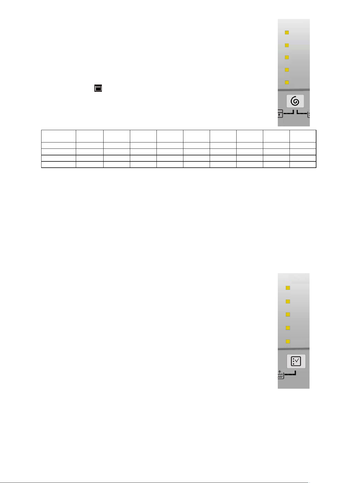
Sensor no. 3: SPIN SPEED (configurable)
Max spin
speed (rpm)
800
1,000
1,000
1,200
1,200÷
1,400
1,200÷
1,400
1,400-
1,600
1,400-
1,600
1,400-
1,600
Intermediate
600
800
800
800
1,000
1,000
1,200
1,200
1,200
Intermediate
400
400
600
400
800
800
800
800
1,000
Intermediate
0 0 400 0 0
400 0 400
800
Min. speed
Rinse hold
Rinse hold
0
Rinse hold
Rinse hold
0
Rinse hold
0
0
L14
L18
S3
L19
L23
S4
The function of the third sensor is dedicated to the spin speed selection, combined with the
five LEDs (L14÷L18) above; the related speed is silk-screen printed beside them on the
control panel.
The initial spin speed is that set for the chosen programme.
Touch the sensor to reduce the spin speed, indicated by the LED near the silk-screen printed
value on the control panel lighting up at the same time to confirm your selection. Once the
lowest speed has been reached, you can, if you wish, select “Rinse hold” and the related
LED beside the symbol silk-screen printed on the control panel lights up,
The next selection will be the highest speed available for the selected programme.
For a quicker selection, hold your finger down on the sensor for longer.
The speeds that can be combined with the five LEDs are shown in the following table.
The recommended intermediate spin speeds are:
800 rpm for the following programmes: Lingerie, Duvet, Shirts, Sport, 14 min., Silk, etc…
1,000 rpm for the Easy-Iron option
1,200 rpm for synthetic fabrics, delicates, wool
If you select the “Rinse hold” option when the cycle ends, the related LED flashes to remind the end user to drain
the water before opening the appliance door.
With the “Easy-Iron” option, the spin speed is reduced to 1,000 rpm even if the spin speed selected is higher; if the
option is deselected, the speed automatically returns to the chosen value
Sensor no. 4: OPTIONS (configurable)
The function of the fourth sensor is dedicated to the choice of option to combine with the
programme, combined with five LEDs (L19÷L23) above, beside which the name of the
related option is silk-screen printed on the control panel.
Touch the sensor when no option has been enabled (all the LEDs are switched off) to light
up the first LED relating to the most important option in the list.
Continue your selection to light up the subsequent LED (from the top down) and the previous
one is switched off, all the way to the last option at the bottom. The next time you press the
sensor all the LEDs will remain switched off.
You can only select one option per programme, as no combinations are possible
For a quicker selection, hold your finger down on the sensor for longer.
The following options can be combined with the first three LEDs (at the top):
Super Quick
Easy Iron
Intensive
Pre-wash
Daily
Half-load
Soak
The two LEDs (at the bottom) are combined with:
Rinse Only – performs the last rinse cycle for the selected programme. If “Extra Rinse” is set, two or more rinse
cycles are added (depending on the configuration)
Spin/Drain – performs the spin cycle for the selected programme, if the selected option is “No Spin” it only drains
off the water.
Technical Support - MDM 11/84 599 78 10-24 Rev.01
Page 12
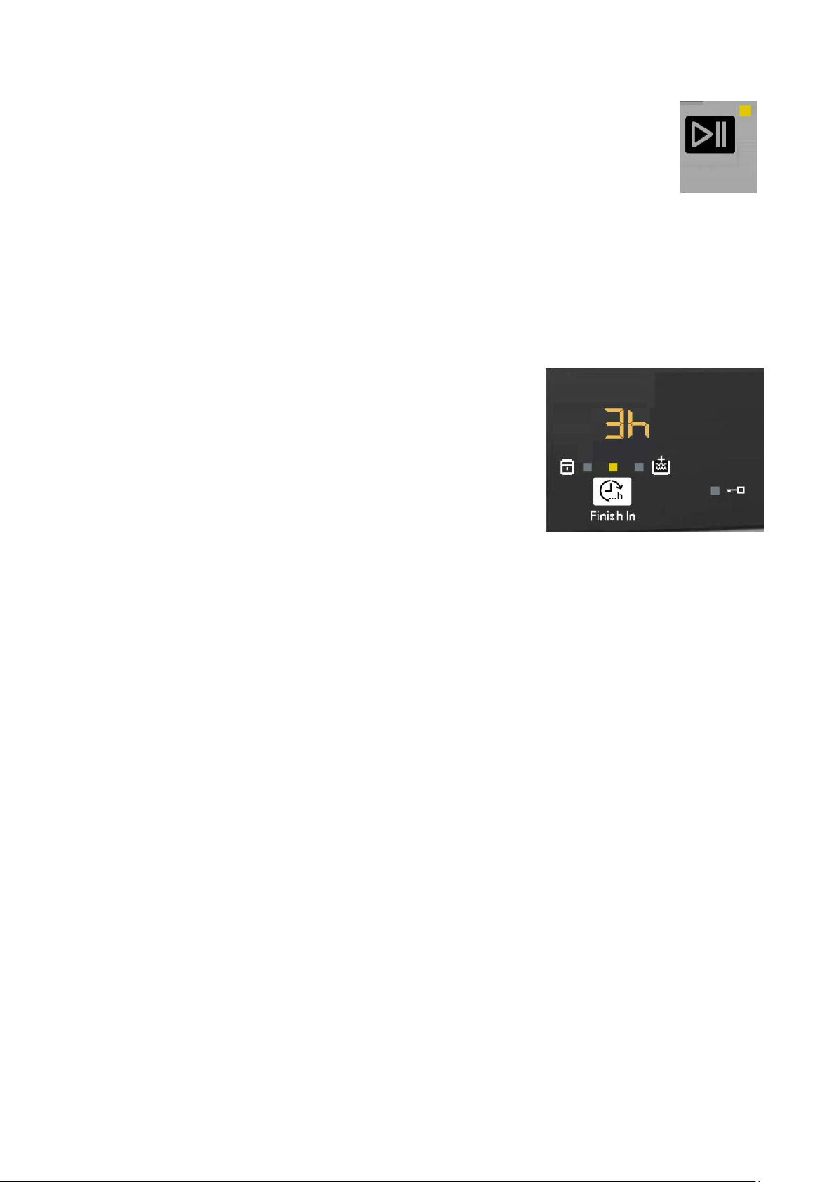
Sensor no.5: START/PAUSE
L24
S5
S6
L26
This sensor has the START/PAUSE function, used to start up a washing programme, after
selecting the washing cycle and required options; it can also pause a cycle that has already
started: to allow you to change selected option or open the door (if the temperature conditions
or water level allow for this).
The cycle re-starts if you touch the sensor again.
The (L24) LED combined with this sensor flashes slowly: in the selection phase, during the
pause and at the end of a cycle with water in the tub.
It stays lit when a cycle is running and turns off when the cycle has ended and the door is
unlocked.
While other sensors when touched immediately change from selected to de-selected, in the
case of this sensor, more time is needed to avoid unwanted cycle start ups or pauses.
Sensor no.6: THE CYCLE FINISHES IN (Finish In)
This sensor allows the end user to programme in how many hours' time
the washing cycle will finish and it is related to LED (26).
In detail, the cycle start can be delayed so as to have the cycle end at the
desired time.
You can select from a minimum of 3 hours to a maximum of 20 hours.
The first time you press the sensor, the display indicates 3 hours and the
related LED (26) lights up to indicate the option is enabled. The next time
you press it, the time increases by 1 hour, up to a total of 10 hours. The
increase is of 2 hours every time you press the button for the range
between 10 and 20 hours.
If the display indicates 20 hours, the next time you press the sensor,
“Finish In” will be disabled and the washing cycle time will be displayed
and the LED (26) will switch off.
For a quicker selection, hold your finger down on the sensor for longer.
Setting an option after selecting “Finish In”
“Finish In” must be enabled after an option has been selected (if necessary) and before you start the cycle. If the
end user, after setting “Finish In”, modifies the programme settings, “Finish In” will be disabled, the LED (26) will
flash once and the display will once again indicate the washing cycle time
“Finish In” after touching the START sensor
Once you have selected the programme and the option (if necessary) and set “Finish In”, the washing cycle starts
when you touch the START sensor; the appliance door is locked and the countdown begins, and is indicated on
the display at one-hour intervals until the start of the washing cycle. Once the “Finish In” time is up, the display
indicates the amount of time necessary to perform the washing cycle, starting the countdown of the cycle with oneminute intervals, until the end of the cycle.
If the appliance is paused during the countdown of the “Finish In” option to change the option and including “Finish
In”, the delay time is deleted and “Finish In” is disabled; touch the sensor and the display will indicate “error”.
Technical Support - MDM 12/84 599 78 10-24 Rev.01
Page 13
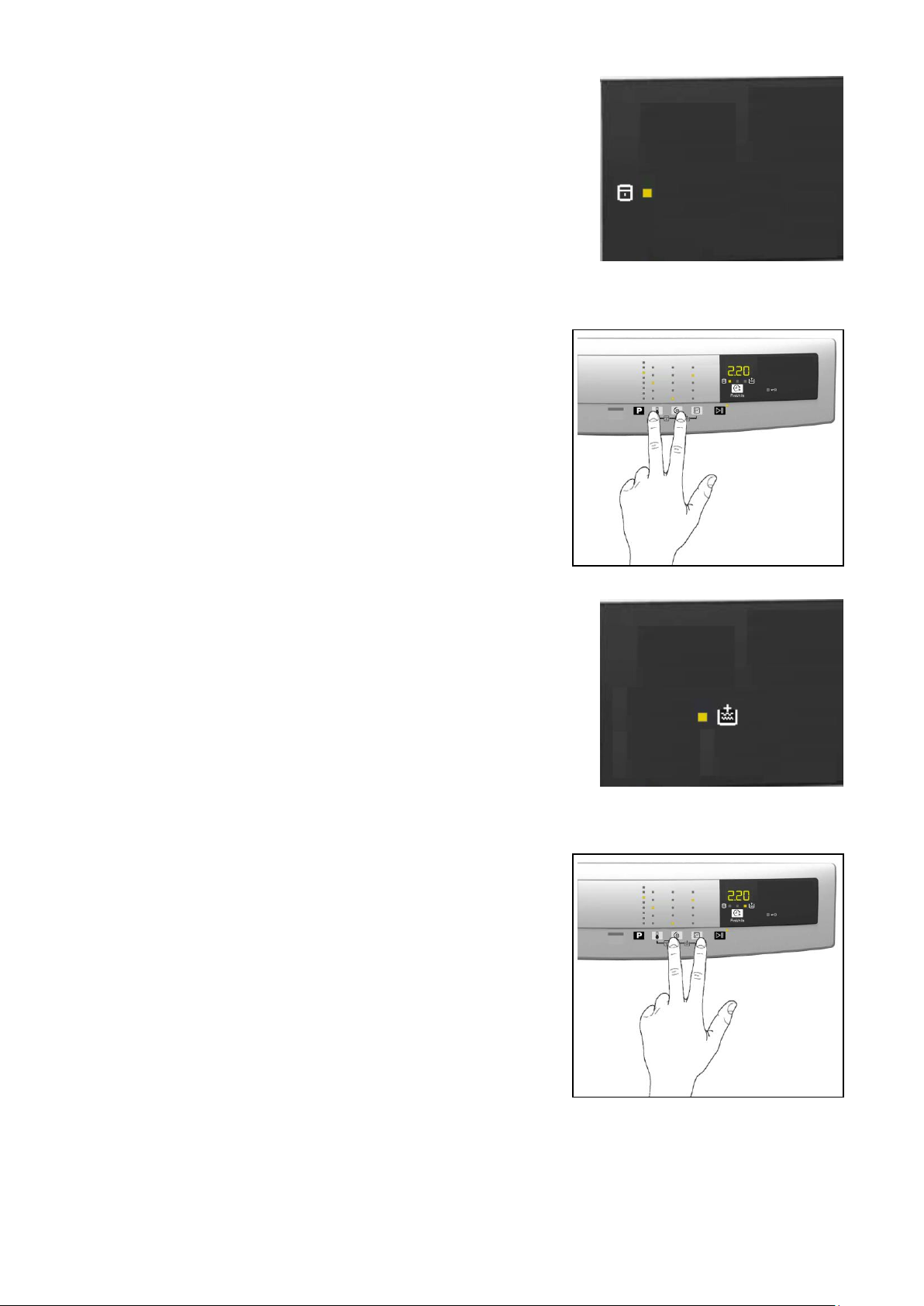
3.2.2.4 Display
L25
L27
Padlock
When the related LED (L25) is lit, it indicates that all the sensors are
disabled to prevent children from altering, starting or pausing the cycle.
When enabled, touch any sensor and the LED flashes three times to
remind the end user that the appliance is locked.
Use the combination of two sensors (touch for approximately 5 seconds) illustrated in the figure below to
enable/disable this option.
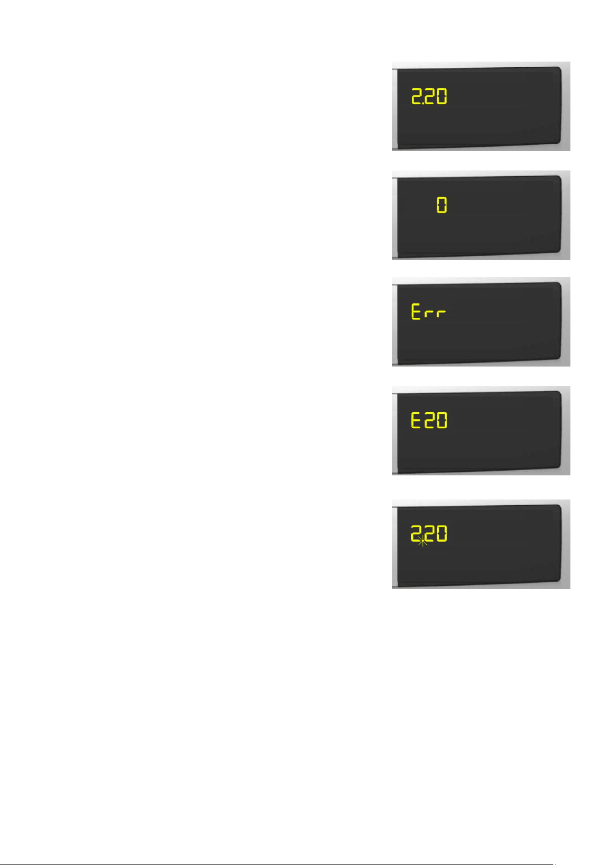
Extra Rinse
When the related LED (L27) is lit up, this indicates that the option is
enabled (it lights up during the washing and rinse cycles, and it remains
switched off during the drain and spin cycle).
The option remains enabled even after the appliance has been turned off
(for subsequent programmes).
Use the combination of two sensors illustrated in the figure below to enable/disable this option.
Technical Support - MDM 13/84 599 78 10-24 Rev.01
Page 14
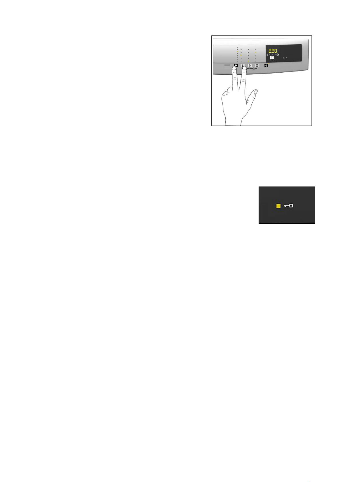
The following information also appears on the display:
Washing programme time
This appears after a washing programme has been selected. This
time corresponds to the time required for the maximum wash load
for each type of programme.
After the programme has started, the time decreases (and is
updated) minute by minute.
When the time is less than an hour, the initial zeros are not
displayed.
End of cycle
End of the programme is indicated by a permanently lit zero
(when the door can be opened).
Selection incorrect
Displays the flashing message “Err”, for one second.
Appears on selecting option that is incompatible with the programme
selected, or when the selector is turned while a cycle is running.
Alarm code
Indicates an anomaly during operation of the machine. Simultaneously
to the displaying of the code on the LCD display, the LED above the
START/PAUSE sensor flashes
Calculate amount of washing
Only for appliances with PROPORTIONAL programmes
After starting the washing programme the dot starts to flash. At this
point the washing machine calculates the amount of washing inside
the drum. When this phase ends the dot lights up fixed and the three
digits display the programme time.
3.2.2.5 Buzzer
This comprises a multi-tone buzzer and sounds in the following cases:
When the machine is turned on and off it emits two different tunes.
When a sensor is pressed it emits a short “Click”
When the cycle ends this is indicated by a special sequence of “three long beeps” repeated at intervals of 15”
for a total of 2 minutes. The sequence can only be stopped by opening the door in appliances where the instant
door safety device with micro-switch is fitted.
In the event of a malfunction in the machine this is indicated by a special sequence of “three short beeps”
repeated 3 times at intervals of 15” for a total of 5 minutes.
All appliances are fitted with the buzzer, and leave the factory with the option enabled. To disable it use the
combination of sensors.
The volume level is set in the factory and cannot be adjusted by the user.
When the buzzer is disabled (using the combination of sensors) it only emits the short “Click” and the sequence of
“three short beeps” when an alarm is triggered.
Technical Support - MDM 14/84 599 78 10-24 Rev.01
Page 15
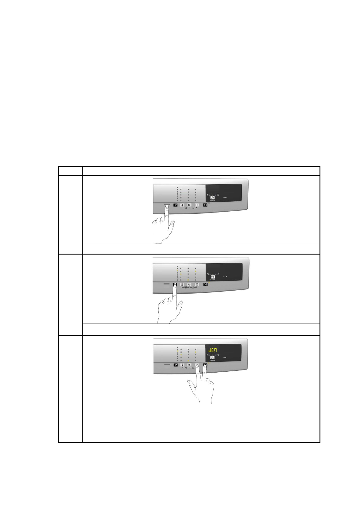
During the programme selection phase, the buzzer can be enabled/disabled with a sensor combination (which may
L28
be silk-screen printed on the control panel or described in the instruction manual), but the alarm signalling remains
enabled.
To enable it, touch the sensors simultaneously for 3 seconds. A short beep will confirm that it has been enabled,
whereas two short beeps will confirm that it has been disabled.
Door lock:
When the related LED (L28) is lit up, the safety device prevents the door opening and
switches off when the door can be opened.
Flashes when the device is about to unlock the door (with door interlock with PTC, which
needs one/two minutes to open).
Technical Support - MDM 15/84 599 78 10-24 Rev.01
Page 16
4 “DEMO” MODE
STEPS
1
Switch on the appliance using the ON/OFF button
2
Use sensor S1 to select the third LED from the top down
3
Simultaneously press the START/PAUSE button and the nearest option sensor
(as shown in the diagram).
Keep your finger above the sensors (for approximately three to five seconds) until:
P6 all the LEDs relating to Sensors S2/S3/S4 flash
P3.0 the display indicates a flashing “dEM” for a short while.
A special cycle is designed to demonstrate the operation of these appliances in shops, without connecting them to
the water mains. This way, any one of the programmes can be selected and, once the start button/sensor has
been pressed/touched (START/PAUSE), the appliance will only perform some of the phases of the programme,
skipping those which cannot be performed (water fill, drain, heating).
The cycle takes place as follows:
the door lock is enabled regularly (door locked during operation, possibility of opening it at the end of the cycle
or when paused)
Motor: all low speed movements are enabled, the pulses and spin are disabled,
the water fill solenoid valves and the drain pump are disabled.
display: as the cycle phases are very fast (one second in the demo cycle corresponds to approximately one
minute in the actual cycle) the end time decreases by 1 unit per second. Bear in mind that the end time does
not always correspond to the actual cycle time.
4.1 Access to DEMO settings
The operations listed below must be carried out within 7 seconds.
4.2 Exiting DEMO mode
Disconnect the power supply to exit demo mode.
Technical Support - MDM 16/84 599 78 10-24 Rev.01
Page 17
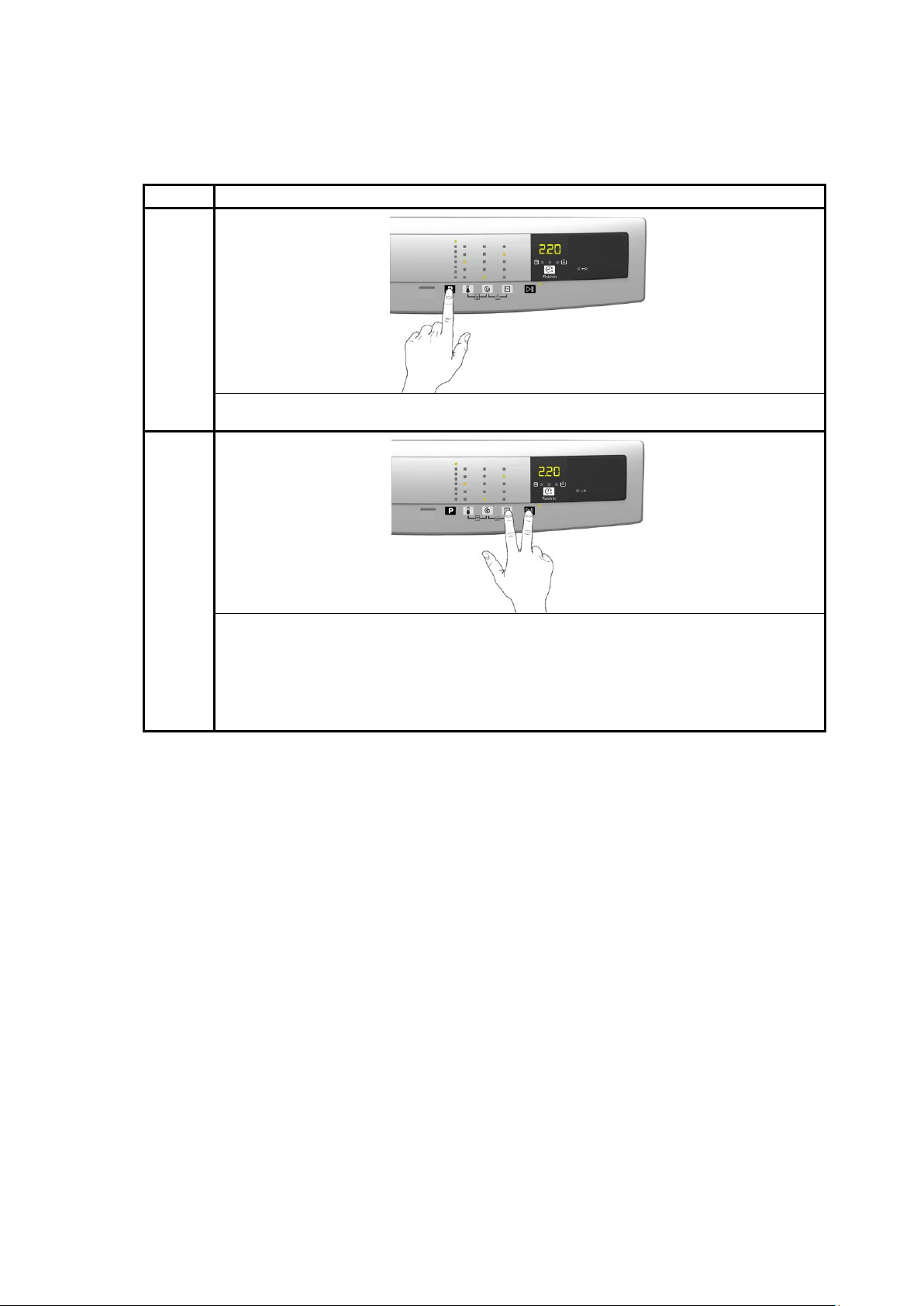
5 DIAGNOSTICS SYSTEM
STEPS
P 3.0
1
Switch on the appliance using the ON/OFF button an wait for the main programme
LED to light up.
2
Simultaneously press the START/PAUSE button and the nearest option sensor
(as shown in the diagram).
Keep your fingers on the sensors (for approximately 3 seconds) until the LEDs
begin to flash in sequence (P3.0, also the symbols inside the display).
5.1 Accessing diagnostics
The operations listed below must be carried out within 7 seconds.
5.2 Quitting the diagnostics system
In order to exit the diagnostic system turn the appliance off and on again using the ON/OFF button.
If “ELE” appears on the display when you turn the appliance on, repeat the operation of switching it on and off.
Technical Support - MDM 17/84 599 78 10-24 Rev.01
Page 18
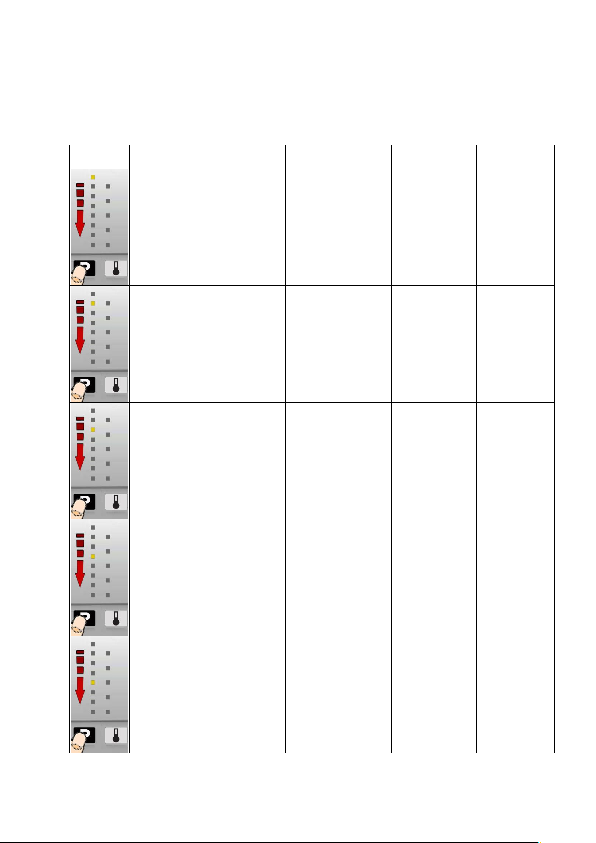
5.3 Phases of the diagnostics test
LED Lamp
lit up
Components activated
Working conditions
Function tested
Display
- Door safety interlock
- Wash solenoid valve
Door closed
Water level below
anti-flooding level
Maximum time
5 mins.
Water fill to wash
compartment
Water level in
the tub (mm)
- Door safety interlock
- Pre-wash solenoid valve
Door closed
Water level below
anti-flooding level
Maximum time
5 mins.
Water fill to
pre-wash
compartment
Water level in
the tub (mm)
- Door safety interlock
- Pre-wash and wash solenoid
valves
Door closed
Water level below
anti-flooding level
Maximum time
5 mins.
Water fill to
conditioner
compartment
Water level in
the tub (mm)
- Door safety interlock
- Third Solenoid valve
Door closed
Water level below
anti-flooding level
Maximum time
5 mins.
Water fill to Third
solenoid valve
compartment
Water level in
the tub is
displayed (mm)
- Door safety interlock
- Fourth solenoid (hot water, if
present)
Door closed
Water level below
anti-flooding level
Maximum time
5 mins.
Water fill to
Fourth solenoid
valve
compartment
Water level in
the tub is
displayed (mm)
Irrespective of the type of electronic board and of the configuration, once the diagnostics system has been activated,
touch sensor S1 to run a diagnostic check of the various components and the alarm reading (touch sensor S1
(Programme) to progress in sequence from the top down, or touch sensor S2 (Temperature) to go back).
The Display indicates the description in the last column of the table below.
(All alarms are enabled in the diagnostic cycle).
Technical Support - MDM 18/84 599 78 10-24 Rev.01
Page 19
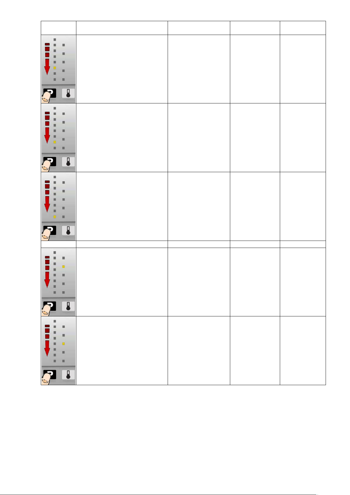
LED Lamp
lit up
Components activated
Working conditions
Function tested
Display
- Door safety interlock
- Wash solenoid, if the water in the
tub is not enough to cover the
heating element
- Heating element
- Recirculation pump
Door closed
Water level above
the heating element.
Maximum time 10 mins
up to 90C. (*)
Warming up
Circulation
Temperature in
°C measured
using the NTC
probe.
- Door safety interlock
- Wash solenoid, if the water in
the tub is not enough to cover
the heating element
- Motor (55 rpm clockwise,
55 rpm anti-clockwise,
250 rpm pulse)
Door closed
Water level above
the heating element
Check for leaks
from the tub.
Drum speed in
rpm/10
- Door safety interlock
- Drainage pump
- Motor up to 650 rpm then at
maximum spin speed (**)
Door closed
Water level lower
than anti-boiling level
for spinning.
Drain, calibration
of analogue
pressure switch
and spin.
Drum speed in
rpm/10
-----
-----
-----
-----
-----
Reading/Deleting
the last alarm
-----
-----
-----
- The LEDs light up in
sequence, the symbols on the
LCD display light up in in
groups and the backlighting
comes on,
- Touch a sensor to turn on the
group of icons in the LCD
screen or the corresponding
LED and the buzzer sounds at
the same time.
Always active
User interface
functions
(*) In most cases, this time is sufficient to check the heating. However, the time can be increased by repeating the phase without
draining the water: pass for a moment to a different phase of the diagnostic cycle and then back to the heating control phase (if the
temperature is higher than 80°C, heating does not take place).
(**) The check at the maximum speed occurs without control of the A.G.S. and no garments must be inside the appliance.
Technical Support - MDM 19/84 599 78 10-24 Rev.01
Page 20
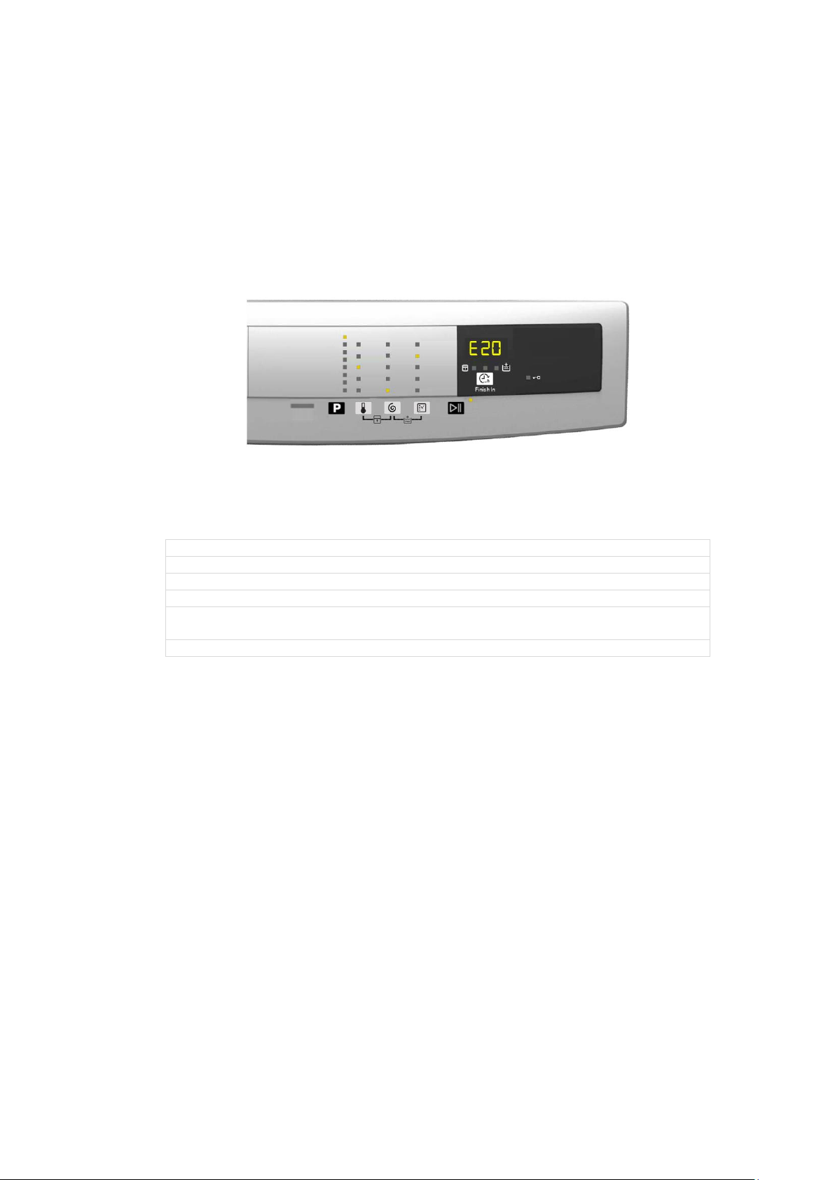
6 ALARMS
E10 – Water fill difficulty (tap closed)
E20 – Drain difficulty (filter dirty)
E40 – Door open
EF0 – Excessive detergent (if displayed)
E91 – No communication between the display board and the main board.
Switch ON/OFF
E92/E93/E94 – Main board not configured correctly.
6.1 Displaying user alarms
When a problem arises with the appliance, “WARNING” appears on the LCD screen, represented by a code (three
digits, indicating the time required for the cycle to end). At the same time the buzzer gives off three short “beeps”
every 20” for a period of 5 minutes.
Once the fault has been repaired the buzzer does not give off any “beeps” and the selected programme appears
on the LCD screen.
Alarms E9x and EHx show the entire code with the red LED + yellow LED, only alarm EHx is not accompanied by
the buzzer sounding.
The alarms displayed to the user are listed below and can also be eliminated by the user:
EF0 – Water leakage (Aqua Control System)
It is displayed to the user, but technical assistance is required to resolve it.
EH0 – Voltage or frequency outside the normal values
It is necessary to wait for power supply voltage and/or frequency to restore nominal conditions.
The alarms are enabled during the execution of the washing programme. With the exception of alarms
associated with the configuration and the power supply voltage/frequency, which are also displayed
during the programme selection phase.
The door can normally be opened (except where specified) when an alarm condition has occurred, on the condition
that:
The water in the tub is below a certain level.
The water temperature is lower than 55°C.
The motor has stopped.
Certain alarm conditions require a drain phase to be performed before the door can be opened for safety reasons:
Cooling water fill if the temperature is higher than 65°C
Drain until the analogue pressure switch is on empty, during a max. 3-minute interval.
Technical Support - MDM 20/84 599 78 10-24 Rev.01
Page 21
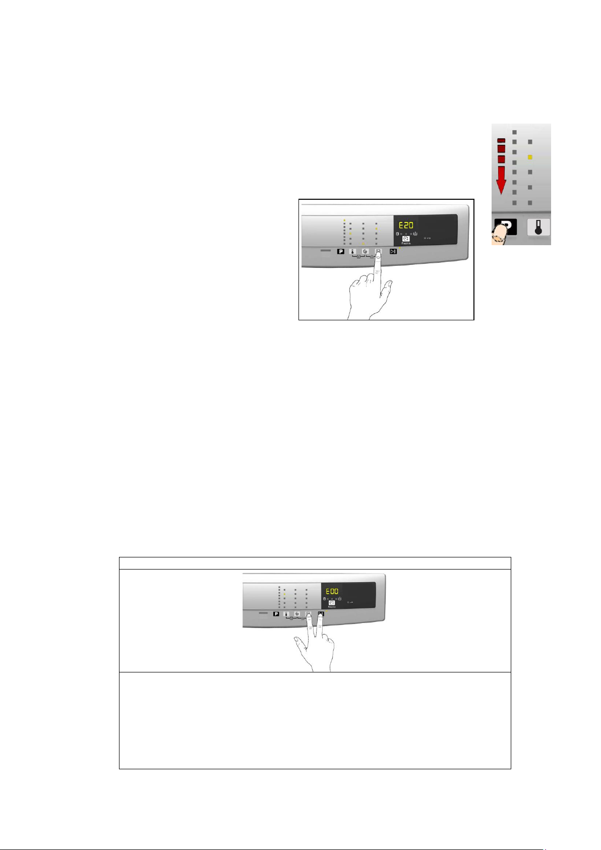
6.2 Alarm reading/display
P 3.0
Enter the diagnostic mode (para. 5.1)
Using sensor S1, select the position in which the LED lights up to display the
alarms.
Simultaneously press the START/PAUSE sensor and the nearest option
sensor (as shown in the diagram).
Keep your finger above the sensors (for at least 5 seconds) until the wording “E00”
appears on the screen.
S1
6.2.1 Displaying the alarm
The last three alarms stored in the FLASH memory of the PCB can be displayed:
Enter the diagnostic mode (para. 5.1)
Irrespective of the type of circuit board and of the configuration, use sensor S1 to select the
LED (see figure opposite) and the display indicates the last alarm.
to display previous alarms, touch the sensor closest to the START/PAUSE sensor in
sequence (as shown in the figure)
To return to the last alarm, touch the START/PAUSE sensor.
6.2.2 Rapid reading of alarms
It is possible to display the last alarm even if the selector is not in the eleventh diagnostics position
or the machine is in normal operation (e.g. while a washing programme is in
progress):
→ Touch the START/PAUSE sensor and the nearest option sensor simultaneously (as if you were entering
DIAGNOSTIC mode) and hold for at least 2 seconds: the LCD display shows the last alarm.
→ The alarm will continue to be displayed until a sensor is touched.
→ The alarm reading system is as described in para. 6.1.
→ While the alarm is being displayed, the appliance continues to perform the cycle or, if in the programme
selection phase, it maintains the previously selected options in memory.
6.2.3 Deleting the last alarm
It is good practice to cancel the alarms stored:
after reading the alarm codes, to check whether the alarm re-occurs during the diagnostic cycle
after repairing the appliance, to check whether it re-occurs during testing
N.B. With this operation all the alarms stored are deleted.
Technical Support - MDM 21/84 599 78 10-24 Rev.01
Page 22
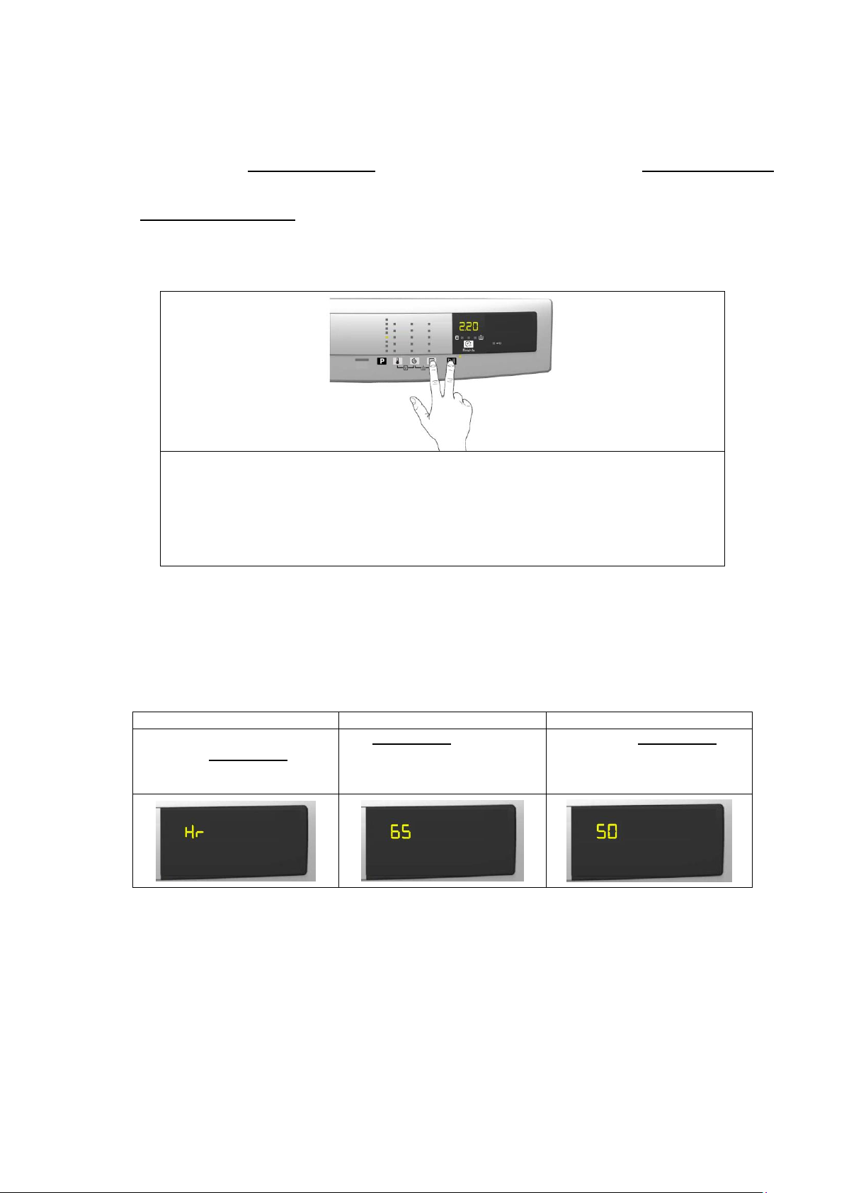
7 OPERATING TIME COUNTER
Switch on the appliance using the ON/OFF button
Use sensor S1 to select the position which lights up the fifth LED.
Simultaneously press the START/PAUSE button and the nearest option sensor (as
shown in the diagram).
Keep your fingers over the sensors until the hours of operation appear on the display
(at least 5 seconds).
Phase 1
Phase 2
Phase 3
For two seconds
It displays: Hr
For two seconds, the following
digits are displayed:
thousands (6)
hundreds (5).
For the next two seconds the
following digits are displayed:
tens (5)
units (0).
S1
Using a specific procedure, the operator can display the total operating time for the appliance, which is counted
from the moment it is first switched on.
The unit can count up to a maximum of 6,550 hours of operating time.
Only the operating time of normal programmes (and not diagnostic cycles) is counted the actual operating time for
the cycle is counted (which does not include pauses, delayed start time, rinse hold time and soaking phases)
The precision of the counter is 30 seconds per programme.
Only whole hours of operation are counted (1 hr and 59 min = 1 hr)
7.1 Reading the operating time
The operations listed below must be carried out within 7 seconds.
7.2 Display of total operating time
This time is displayed with a sequence of two digits at a time: the first two digits indicate thousands and hundreds,
the second two digits indicate tens and units.
For example, if the operating time is 6,550 hours, the display will show the following sequence:
At the end of phase three (after the tens and units are displayed), the cycle is repeated.
To return to normal mode, either: switch off the appliance, press a key
Technical Support - MDM 22/84 599 78 10-24 Rev.01
Page 23
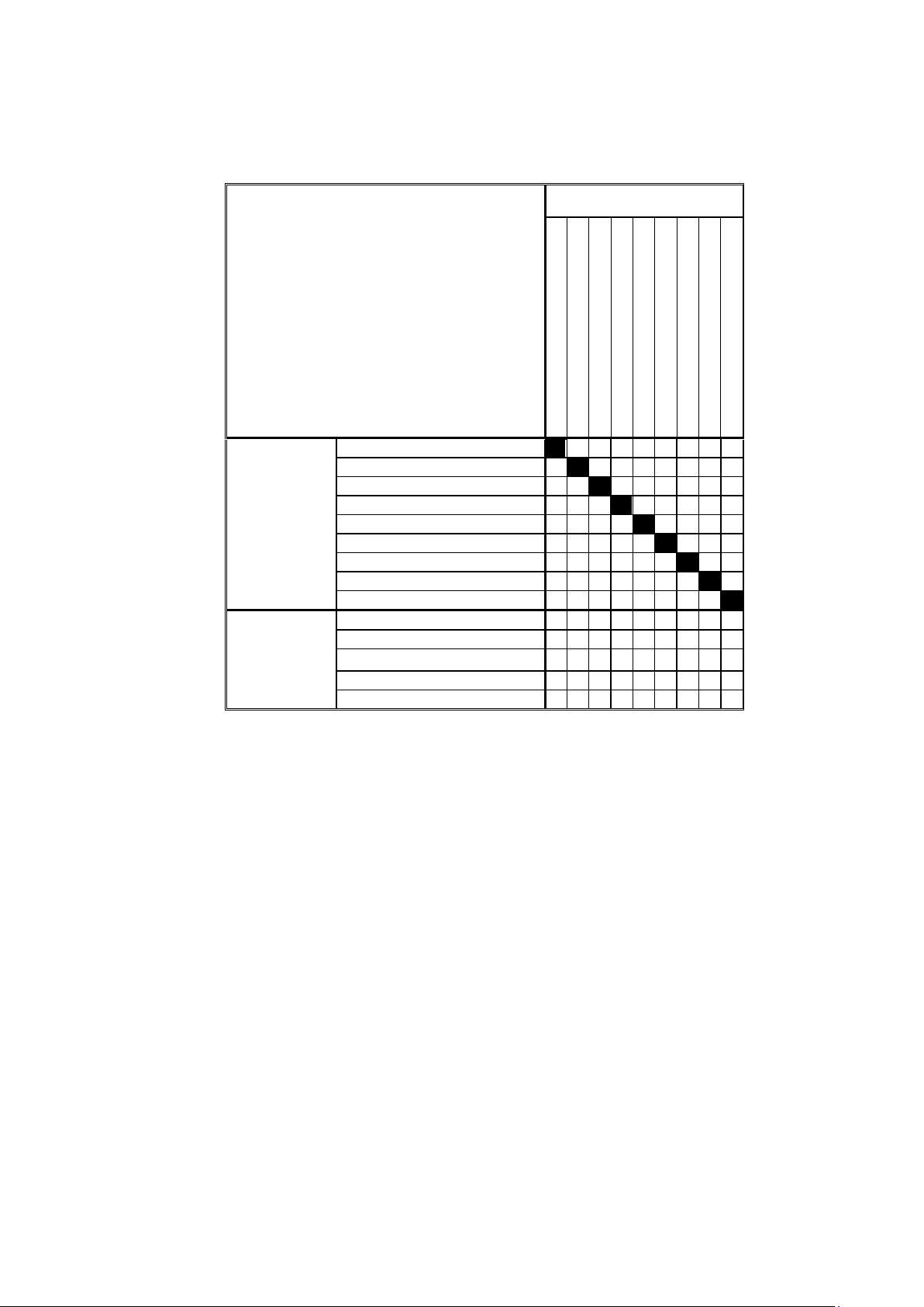
8 OPTIONS
OPTIONS
Rinse hold
Pre-wash
Extra-rinse
Easy-iron
Economy
Cupboard Dry
Super Quick
Spin Speed Reduction
No Spin
Compatibility with
OPTIONS
Rinse hold
X X X X X X
Pre-wash
X X X X X X X X
Extra-rinse
X
X X X X X X
X
Easy Iron
X X X X X X X X
Economy
X X X
X X X
X
Cupboard Dry
X X X
X
X X
Super Quick
X X X X X X X
Spin Speed Reduction
X X X X X X
No Spin
X X X X X X
Phases where
selection/
modification
is possible
Selection
X X X X X X X X X
Pre-wash
X X
X
X X
Wash
X X
X
X X
Rinses
X
Spin
8.1 Compatibility between options
The delayed start is compatible with all programmes except for Drain; the maximum time
selectable is 20 hours.
The selection of the spin cycle is available for all programmes, except for Drain/Extra Silent.
Technical Support - MDM 23/84 599 78 10-24 Rev.01
Page 24

8.2 Description of options
Rinse hold
During the cycle the intermediate rinses and spins are performed.
Stops the appliance with water in the tub before the final spin cycle.
Once the Rinse Hold has ended, the appliance rotates the drum every two minutes for up to a maximum of
18 hours, after which it stops.
To drain the water, simply press the START/PAUSE button to run the drain and spin cycles.
Pre-wash
Adds a pre-wash phase at the start of the cycle with water heating to 30°C (or cold, if selected).
In COTTON and SYNTHETICS cycles, performs a short spin before passing on to the washing phase.
This option cannot be selected for WOOL and HAND WASH cycles.
EXTRA-rinse
Adds two rinses to the cycles where featured
Eliminates the spin at the end of washing.
No spin
It eliminates all the spin phases.
It adds three rinses to the COTTON cycle and one to the SYNTHETIC FABRICS cycle.
Stains
Adds a 5-minute motor movement phase after heating to 40C.
Water flow to the pre-wash/stains compartment to introduce the special stain-removal product
This option cannot be selected for WOOL and HAND WASH cycles.
No spin
It eliminates all the spin phases.
It adds three rinses to the COTTON CYCLE and one to the SYNTHETIC FABRICS cycle.
Daily
Modifies the structure of the COTTONS - SYNTHETICS - DELICATES cycles to obtain good washing
performance in a short space of time.
Super quick
Modifies the structure of the wash phase of the COTTONS - SYNTHETICS - DELICATES cycles by half a
load.
Delayed start time
Adds a pause before the start of the programme:
See description on page 12 “Finish In”.
To start the cycle immediately after the countdown to the delayed start has already begun:
press the Start/Pause button, cancel the delay time by pressing the relevant button, then press Start/Pause
again.
Easy-iron
In COTTON programmes:
Adds three rinse cycles
Eliminates intermediate spin cycles
Performs a pulse spin phase before the final spin
Adds an “untangling” phase after the spin cycle.
In SYNTHETIC FABRICS programmes:
It reduces the heating temperature in 50/60°C cycles to 40C
Increases the wash time
Prolongs the cooling phase at the end of the wash phase
Adds one rinse cycle
Adds an “untangling” phase after the pulse spin cycle
Technical Support - MDM 24/84 599 78 10-24 Rev.01
Page 25
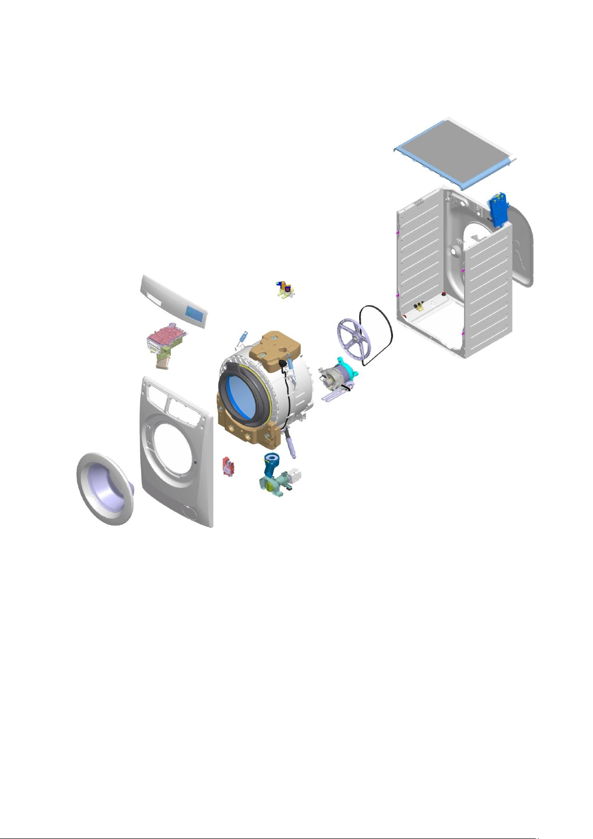
9 TECHNICAL CHARACTERISTICS
1. Door
2. Front panel
3. Door Lock
4. Control panel
5. Drainage pump
6. Drain pipe assembly
7. Shock absorbers
8. Detergent dispenser
9. Washing unit suspension springs
10. Front counterweight
11. Solenoid valves
12. Washing unit
13. Upper counterweight
14. Analogue pressure switch
15. Heating
16. Pulley
17. Motor
18. Belt
19. Back unit casing
20. Main electronic circuit board
21. Worktop
22. Back panel
1
2 3 4 5 6 7 8 9 11
17
13
14
15
18
10
16
12
19
20
21 9 22
9.1 Construction characteristics (with drain filter removable from the outside)
Technical Support - MDM 25/84 599 78 10-24 Rev.01
Page 26
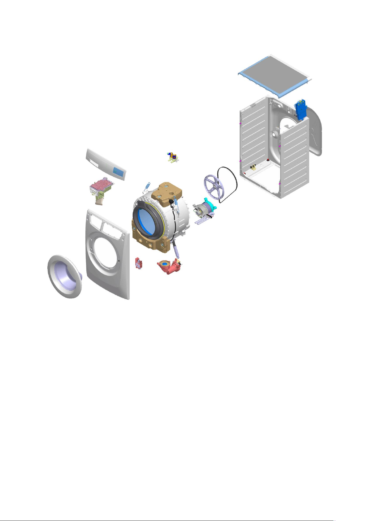
9.2 Construction characteristics (with drain filter not removable from the outside)
1. Door
2. Front panel
3. Door Lock
4. Control panel
5. Drainage pump
6. IDB
7. Shock absorbers
8. Detergent dispenser
9. Washing unit suspension springs
10. Front counterweight
11. Solenoid valves
12. Washing unit
13. Upper counterweight
14. Analogue pressure switch
15. Heating
16. Pulley
17. Motor
18. Belt
19. Back unit casing
20. Main electronic circuit board
21. Worktop
22. Back panel
1
2 3 4
5 6 7 8 9
11
17
13
14
15
18
10
16
12
19
20
21 9 22
Technical Support - MDM 26/84 599 78 10-24 Rev.01
Page 27
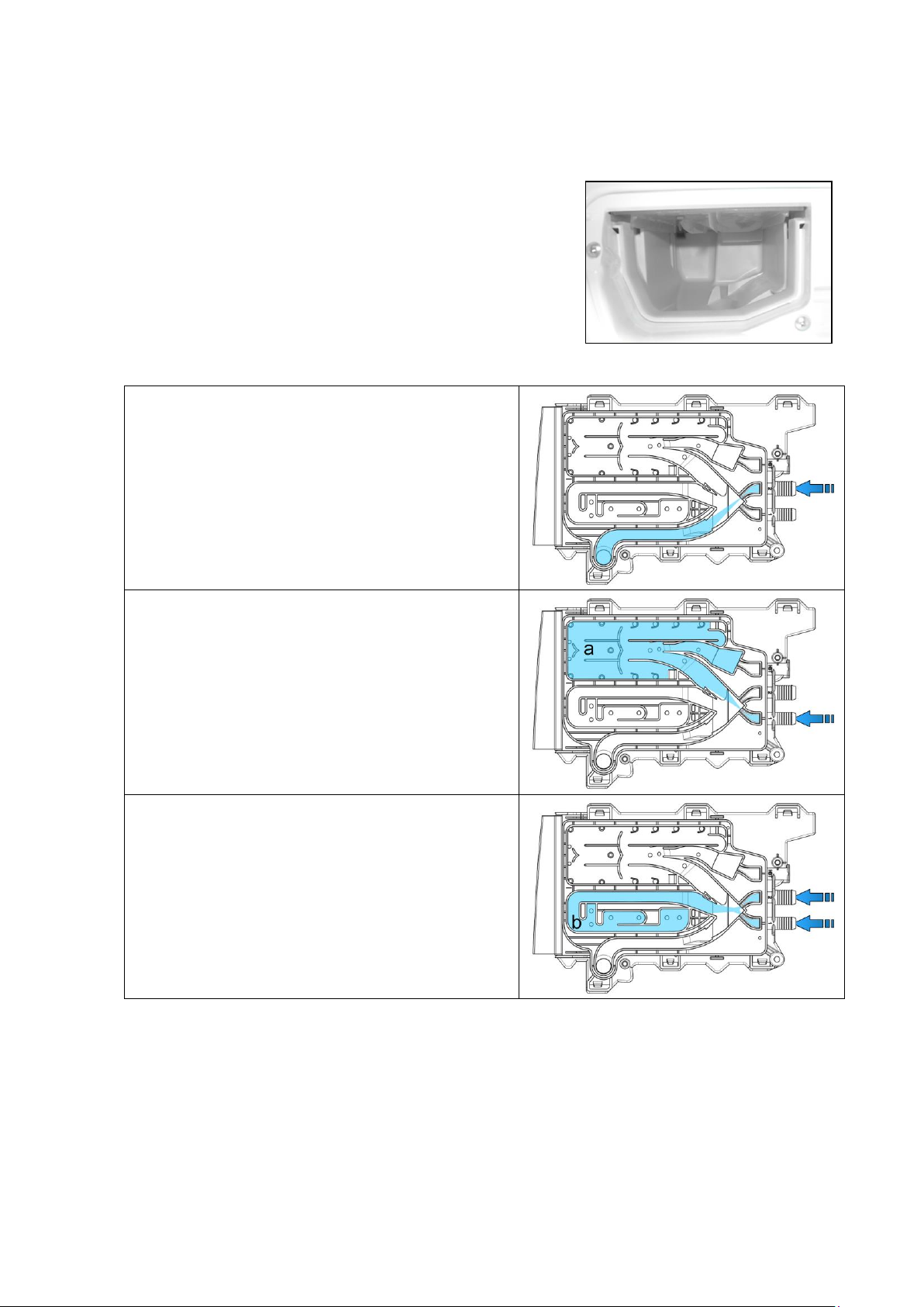
9.3 Detergent dispenser
Water fill directly to tub
(pre-wash solenoid)
There is no pre-wash compartment. If necessary, the
detergent must be introduced directly into the drum.
Water fill to wash compartment
(wash solenoid)
In all models: compartment “a” is used to hold the
detergent loaded at the start of washing.
In the event of stains, mix stain removers with the
washing detergent (for powder detergent).
Water fill to conditioner compartment
(pre-wash and wash solenoid valves)
In all models: compartment “b” is used to contain the
conditioner, which is removed with the water of the last
rinse.
New detergent drawer assembly, with a dispenser assembly incorporated
at the front, which is inserted into the detergent inlet pocket of the porthole
bellows seal.
Operating principle of the conveyor.
Technical Support - MDM 27/84 599 78 10-24 Rev.01
Page 28
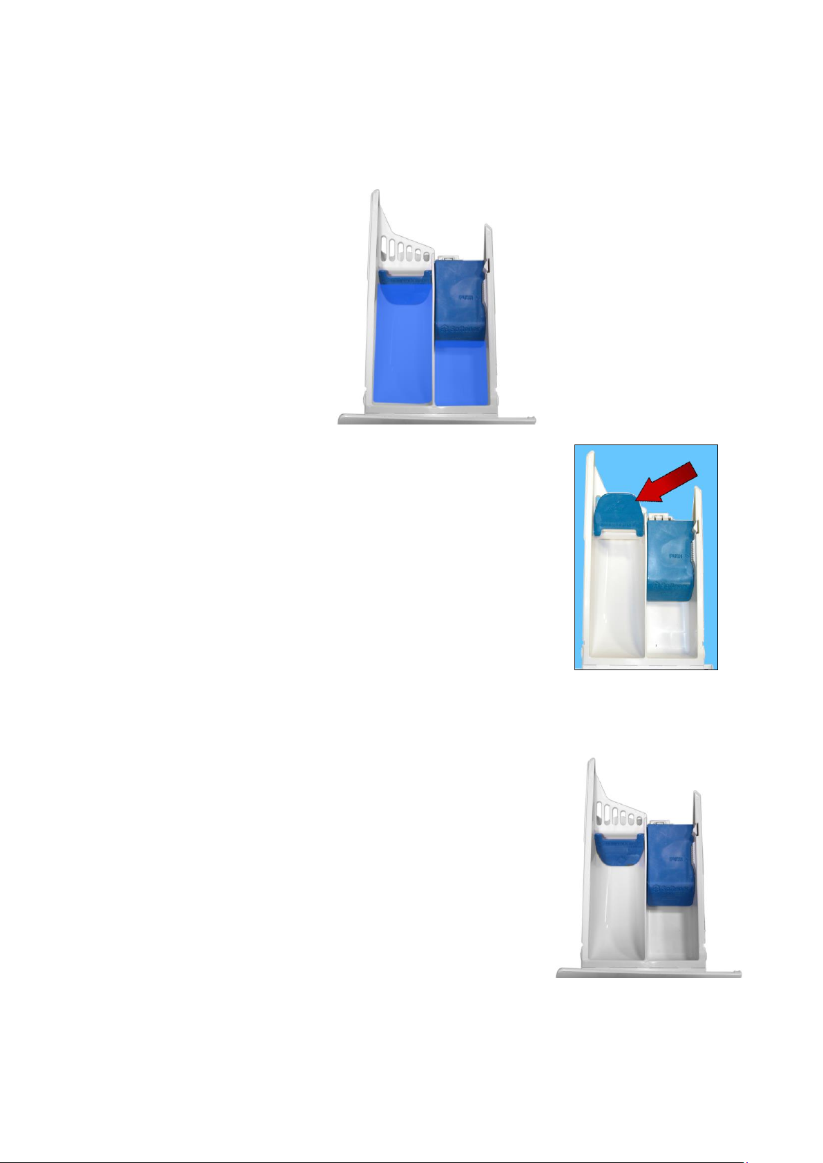
9.4 Detergent drawer
a
b
The detergent dispenser is designed for use with: powder detergent or liquid detergent.
A flap has been fitted inside compartment “a” where the detergent is introduced, which can be flipped up or
down.
Flip it up to use powder detergent.
Position of the flap when the appliance leaves the factory (see figure).
To modify the position of the flap, pull the detergent dispenser out (see page 59).
Flip the flap down to use liquid detergent.
For further details, read the instruction manual.
Technical Support - MDM 28/84 599 78 10-24 Rev.01
Page 29
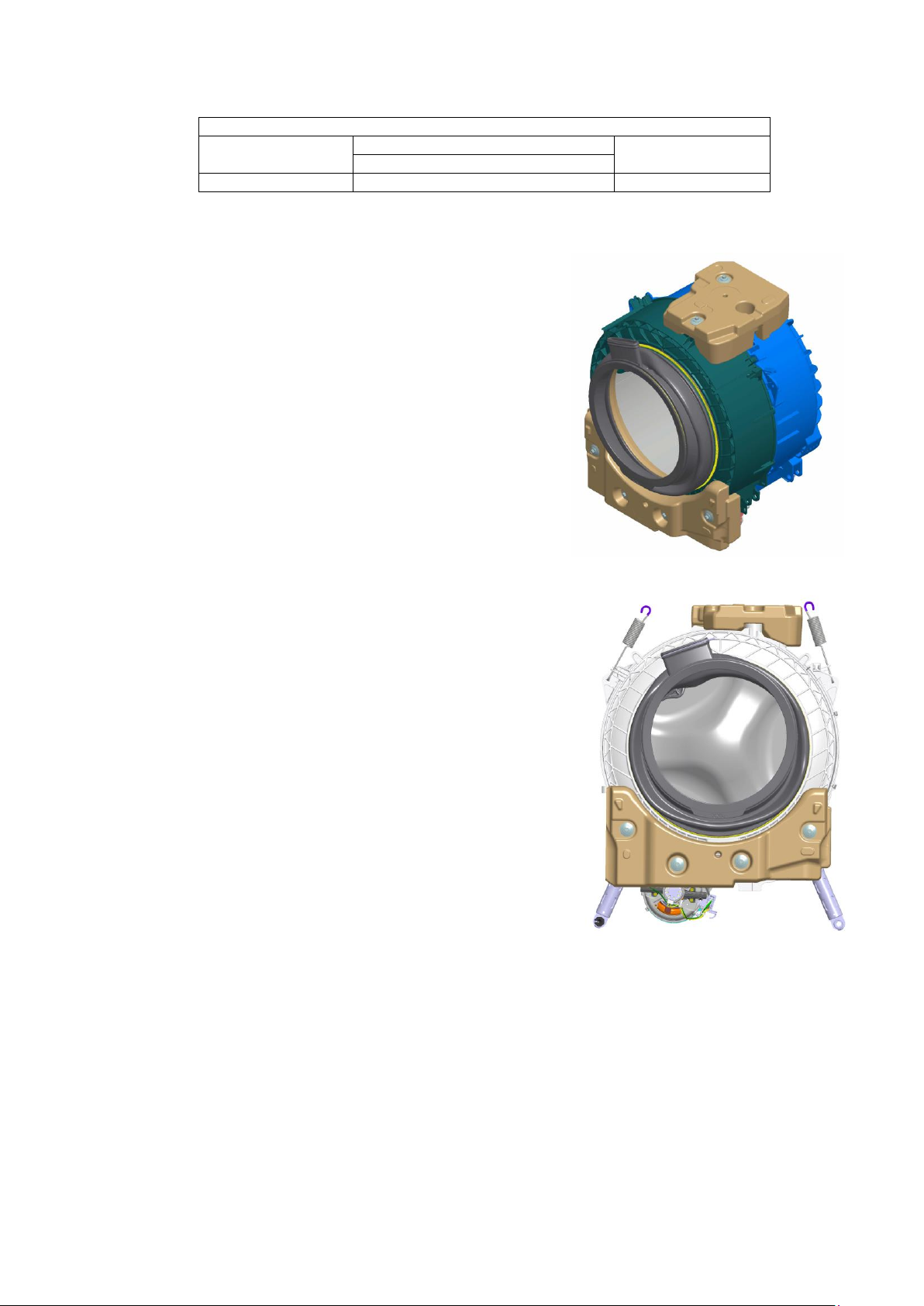
9.5 Washing unit
WASHING UNIT
Type
Load capacity (cottons)
Drum volume
max.
P49
7/8 Kg
53 litres
1
2 3 4 5 6
7
8 8 10
9
The washing unit is made up of:
A back casing (1) and a front casing (2), welded together to form the
welded tub. Inside this is the drum (6) (made of stainless steel) with
the three blades (7) (in carboran) snap-fastened to the drum.
To balance the unit during the washing movements and during the
spin phases, the two counterweights are secured in place with screws:
one at the front (3) and one at the top (4).
The bellow seal (5) is fixed at the front.
The washing unit is suspended by two coil springs (8) attached to the
top crosspiece, and the oscillations are dampened by two shock
absorbers, one on the right (9) and one on the left (10) (looking
straight at the front of the appliance).
Technical Support - MDM 29/84 599 78 10-24 Rev.01
Page 30
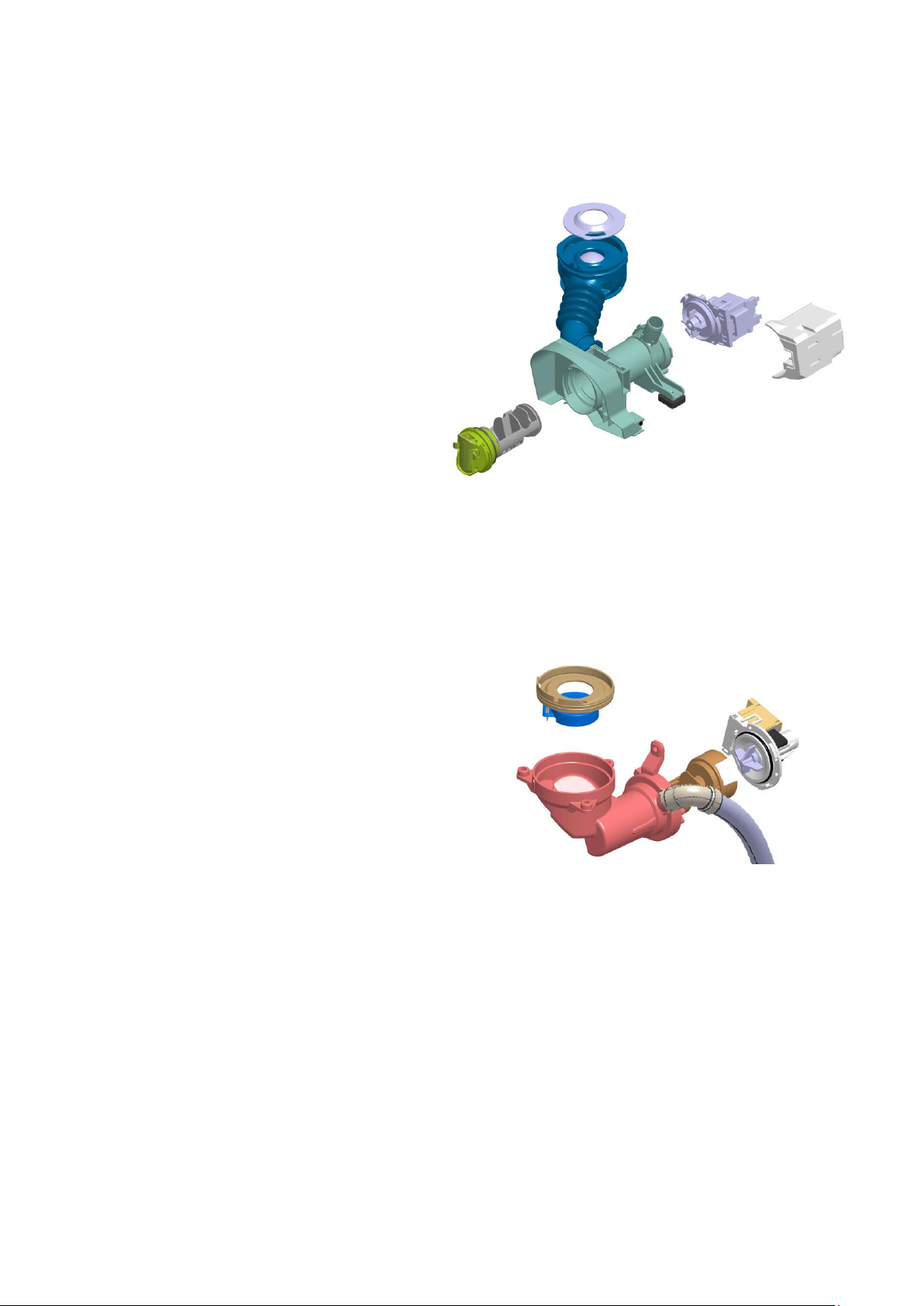
1 2 3 4 5
6 7 8 1 2 3 4 5 6
9.6 Water circuit
9.6.1 Traditional OKO version drain circuit (with drain filter removable from the outside)
1. Diaphragm ring
2. Ball
3. Filter body-tub drain pipe
4. Filter body assembly
5. Filter or needle trap
6. Drainage
7. Drainage pump
8. Drain pump protection
9.6.2 OKO/IDB version drain circuit (with drain filter not removable from the outside)
1. Diaphragm ring
2. Floating valve
3. IDB (Integrated Drain Body)
4. Filter or needle trap
5. Drain pipe
6. Drainage pump
For further details, see page 76
Technical Support - MDM 30/84 599 78 10-24 Rev.01
Page 31
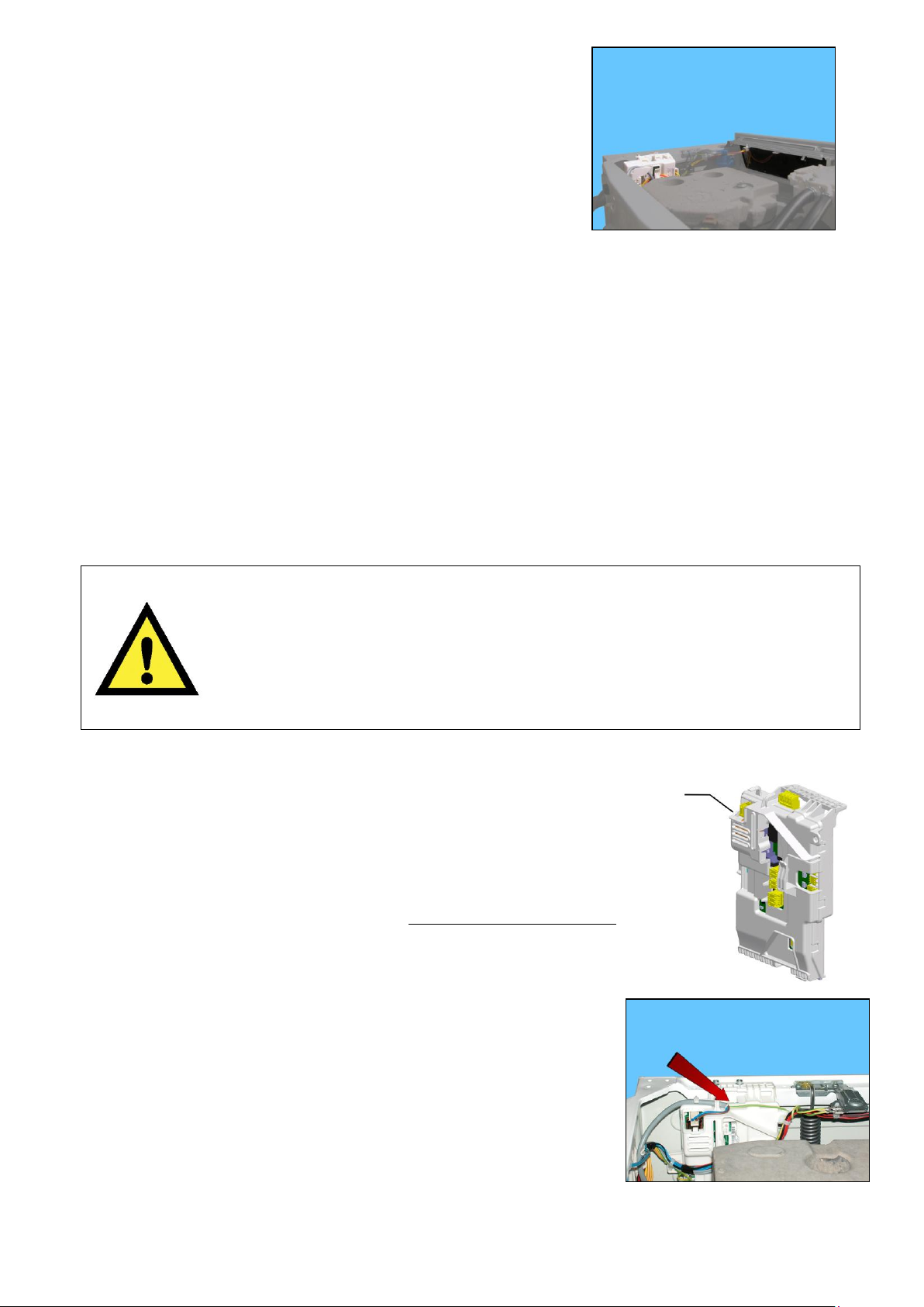
9.7 Electronic control
Any programming/updating/diagnostics operation carried out with the board
installed on the appliance and the mains plug disconnected from the socket.
If one of these operations is accidentally carried out when plugged in to the socket,
on completing the operation, the appliance will remain turned off when restarting;
disconnect the plug from the socket and wait at least 40 minutes before starting up
the appliance (any operation will only create further delay).
2
1
587
The electronic control is made up of:
1. Main electronic circuit board
2. Control/display circuit board
3. INVERTER motor control board where featured (not shown in
the figure).
The control/display PCB contains: the display (where featured), to display the programme information; the touch
sensors, to adjust the temperature, the spin speed and possibly select an option, the START/PAUSE button, the
ON/OFF button and lastly the LEDs which (when lit) indicate the selections made.
The commands acquired by the display board are sent to the main circuit board, which powers all the electrical
components (cold water solenoid valve, drain pump, heating element and door safety device, etc.) and
concurrently:
It controls the level of water via the analogue pressure switch.
It controls the state of the door.
It controls the speed of the motor.
It controls the temperature of the wash water via the NTC probe inserted in the heating element.
It controls the voltage and frequency of the power supply and ensures they are close to the rated ones.
It controls the flow of water through the solenoid valve via the flowmeter (where featured).
To guarantee proper performance of the washing cycle.
9.7.1 Programming/Updating the main circuit board
In the Service Notes the main circuit board (587) is identified with two spare parts codes:
Code 973 914… identifies the pre-programmed board.
Code 132… identifies the unprogrammed board.
The circuit board can be programmed/updated using the Sidekick application.
For further information, please refer to the instructions provided/illustrated in the
course entitled Sidekick Guide >> at the link (http://electrolux.edvantage.net) on
the Electrolux Learning Gateway portal.
To update/program the main board, insert the Sidekick connector in the position
shown by the red arrow:
Technical Support - MDM 31/84 599 78 10-24 Rev.01
Page 32
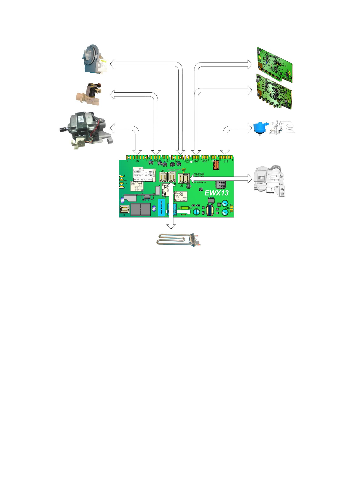
P3.0
P6
Display boards
Main board
Drainage pump
NTC
Device -
door safety
interlock
Heating element
Motor
Solenoid valve
Cold water
Analogue
9.7.2 Electrical features
Technical Support - MDM 32/84 599 78 10-24 Rev.01
Page 33
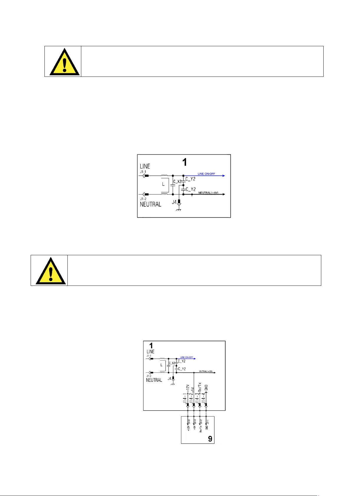
10 ELECTRICAL COMPONENTS
When replacing any of the components, please refer to the code shown in the
list of spare parts relating to the appliance being repaired.
Warning the sensors located in the display boards could be at a potential of
220 Volts.
1. Main electronic circuit board
9. Display board
1. Main electronic circuit board
10.1 Noise filter
10.1.1 General characteristics
This device is connected to the electricity power line input of the appliance and avoids the emission of radio
frequency disturbances in the power network. It is incorporated into the main board.
10.2 Display board
The main circuit board (1) supplies the power supply voltage to the control/display board.
The programmes can be selected by touching the related touch sensor, which can also be used to: select options,
start or pause the appliance.
The buzzer - where featured - is powered by the display board.
Technical Support - MDM 33/84 599 78 10-24 Rev.01
Page 34
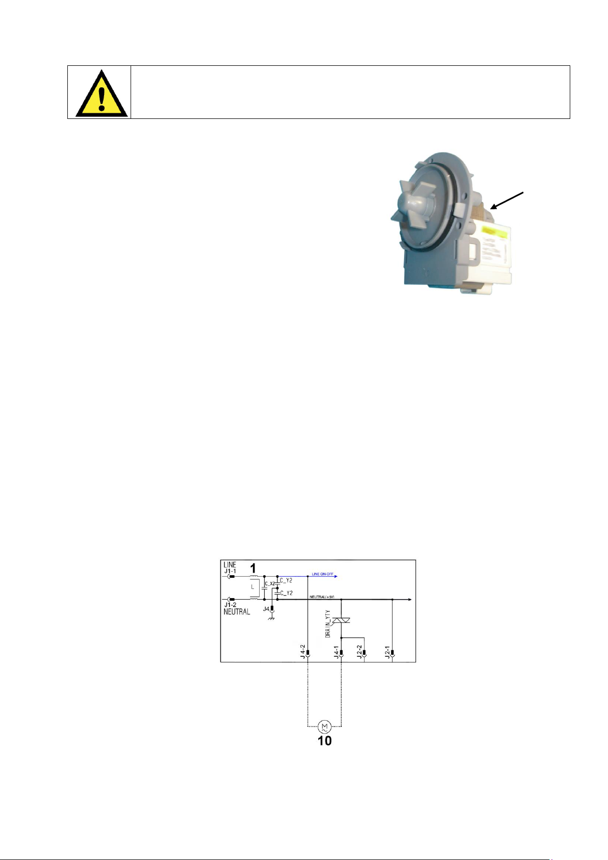
10.3 Drainage pump
When replacing the pump, please refer to the code shown in the list of spare parts
relating to the appliance.
1 Main electronic circuit board
10 Drainage pump
1 2 3
10.3.1 General characteristics
1 Wheel
2 Rotor
3 Stator
The pump, which drains the water at the end of the various washing cycle phases, is centrifugal and is activated by
a synchronous motor.
The rotor consists of a permanent magnet and the direction of rotation can be either clockwise or anticlockwise.
It can turn by approximately a quarter of a revolution without turning the wheel. Consequently, if a foreign body is
stuck in the wheel, the rotor can perform small movements clockwise and anticlockwise until the foreign body is
released.
The flow rate of these pumps is approximately 18÷20 l/min, and the maximum head is 90 cm. above ground level.
Fitted with overload cut-out.
Important
Synchronous pumps, when powered on empty (disconnected from the water circuit), may not start in some cases
because their very construction makes them need an antagonist torque on the wheel to allow the rotor to move in
one of the two directions.
The pumps should therefore only be tested once fitted to the appliance, after a little water has been filled.
The drain pump is powered by the main circuit board through a triac, as follows:
For a pre-determined period (and an alarm might be displayed - see table of alarms).
Until the electronic pressure switch closes on empty, after which the pump is actuated for a brief period or
passes to the subsequent phase.
Technical Support - MDM 34/84 599 78 10-24 Rev.01
Page 35
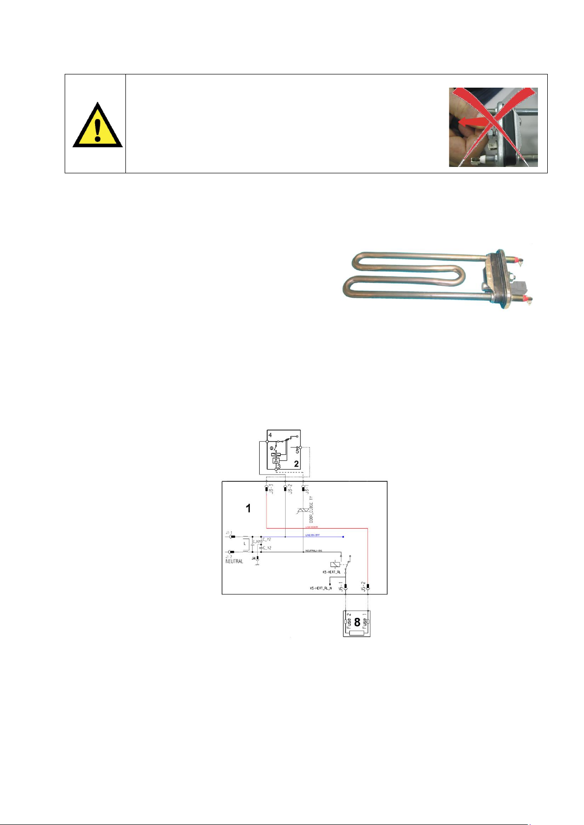
10.4 Heating element
When replacing the heating element, please refer to the code
shown in the list of spare parts relating to the appliance.
It is strictly forbidden to tamper with the heating element in any
way!!! (e.g. replace the NTC probe, etc...)
1 Main electronic circuit board
2 Door safety interlock
8 Heating element
1
2
10.4.1 General characteristics
1. NTC probe
2. Heating element
The heating element of the washing water is armored, i.e. it is inserted in sealed tubular stainless steel casing.
It is powered by the relays located on the circuit board. It is fitted with two thermal fuses which trip if the
temperature of the heating element exceeds the values for which they were calibrated.
(In the event of a fault an alarm will be displayed - see table of alarms).
Technical Support - MDM 35/84 599 78 10-24 Rev.01
Page 36
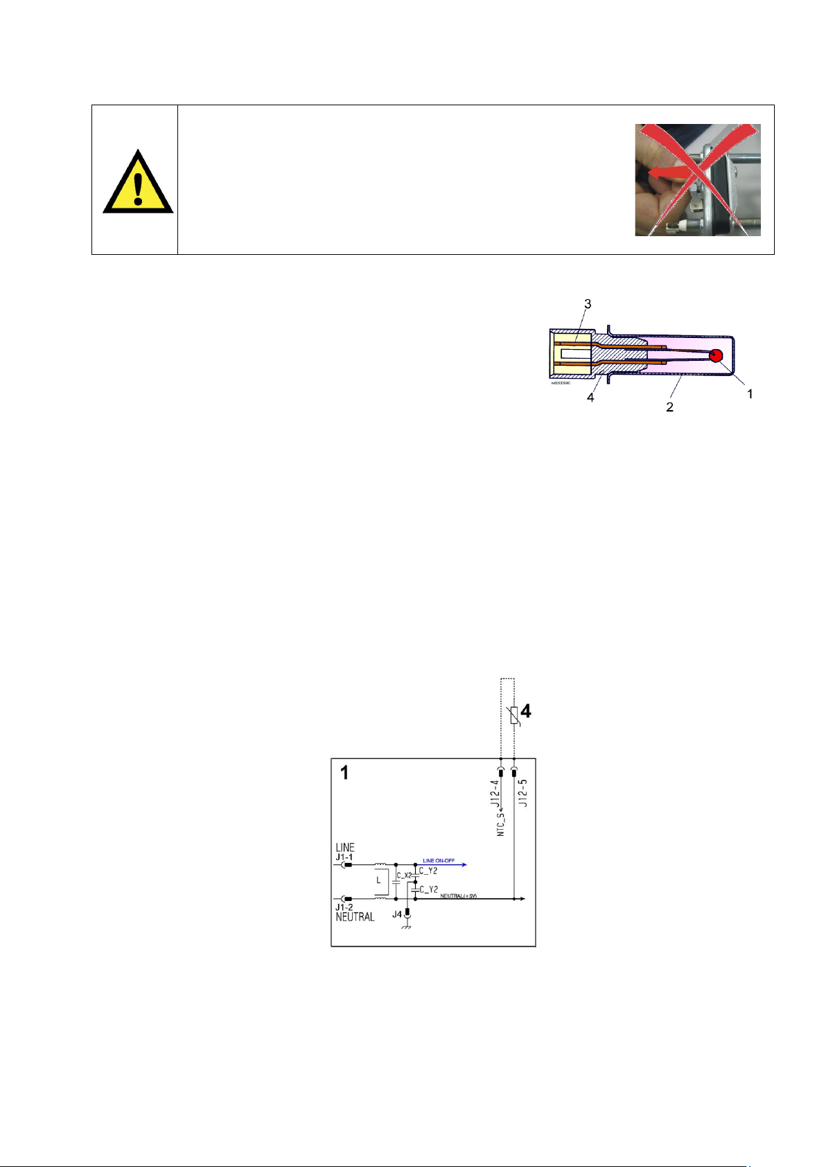
10.5 Temperature probe
When replacing the heating element, please refer to the code
shown in the list of spare parts relating to the appliance.
It is strictly forbidden to tamper with the heating element in any
way!!! (e.g. replace the NTC probe, etc...)
1. Main electronic circuit board
4. NTC probe
10.5.1 General characteristics
1. NTC heating element
2. Metal capsule
3. Terminals
4. Plastic casing
An NTC type probe is used to control the washing temperature: it is built in such a way that its internal resistance
decreases as the temperature rises. This drop in resistance is detected by the electronic control which, when the
desired temperature is reached, disconnects the heating element.
The temperature of the water is controlled by the circuit board by means of an NTC temperature probe incorporated
in the heating element.
In the event of a fault (short-circuit or stoppage) an alarm will be displayed - see table of alarms.
Technical Support - MDM 36/84 599 78 10-24 Rev.01
Page 37
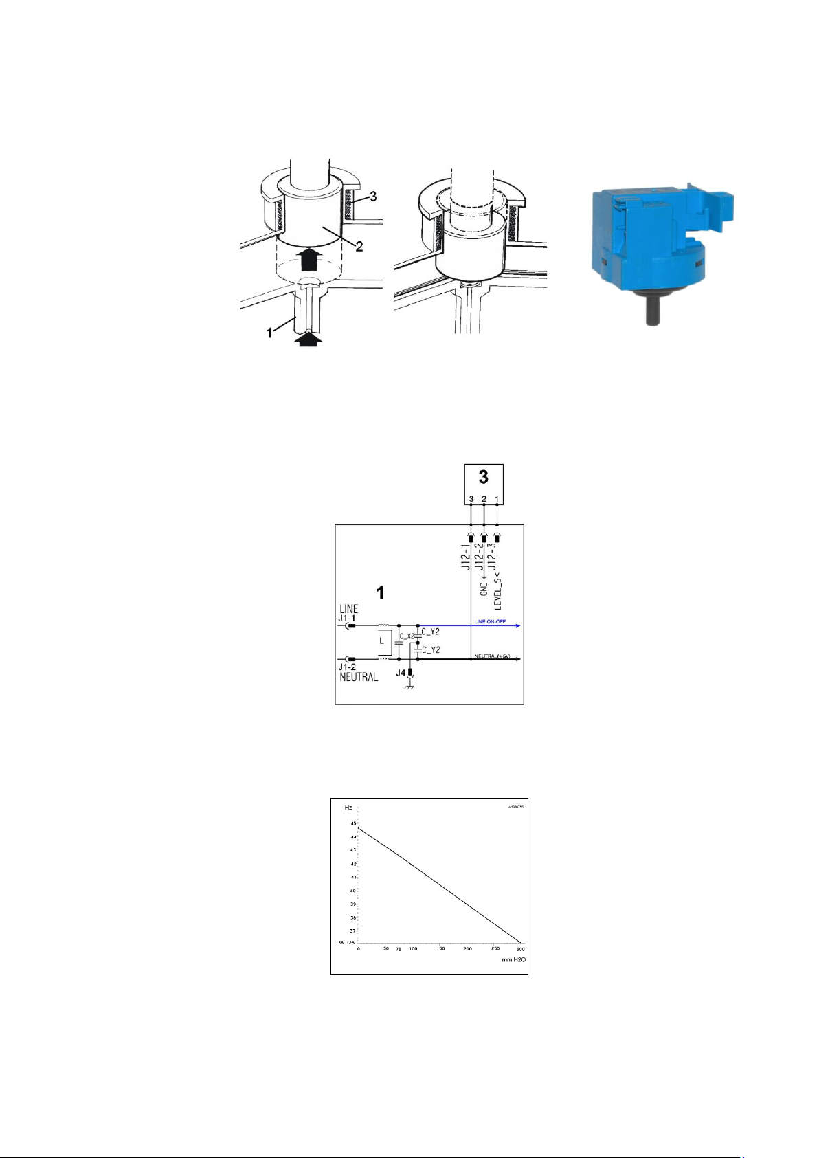
10.6 Analogue pressure switch
1. Main electronic circuit board
3. Analogue pressure switch
10.6.1 General characteristics
The electronic pressure switch is an analogue device that controls the water level in the tub, used in models with
electronic control system, and it is directly connected to the main PCB.
1. small pipe
2. core
3. oscillating coil
The pressure switch is connected via a pipe to the pressure chamber.
When water is introduced into the tub, this creates a pressure inside the hydraulic circuit that causes the
membrane to change position. This in turn modifies the position of the core inside the coil, thus changing the
inductance and the frequency of the oscillating circuit.
The PCB recognizes how much water has been introduced into the tub according to the frequency.
Operating frequency variation according to the quantity of water in the tub.
In the event of a fault an alarm will be displayed - see table of alarms.
Technical Support - MDM 37/84 599 78 10-24 Rev.01
Page 38
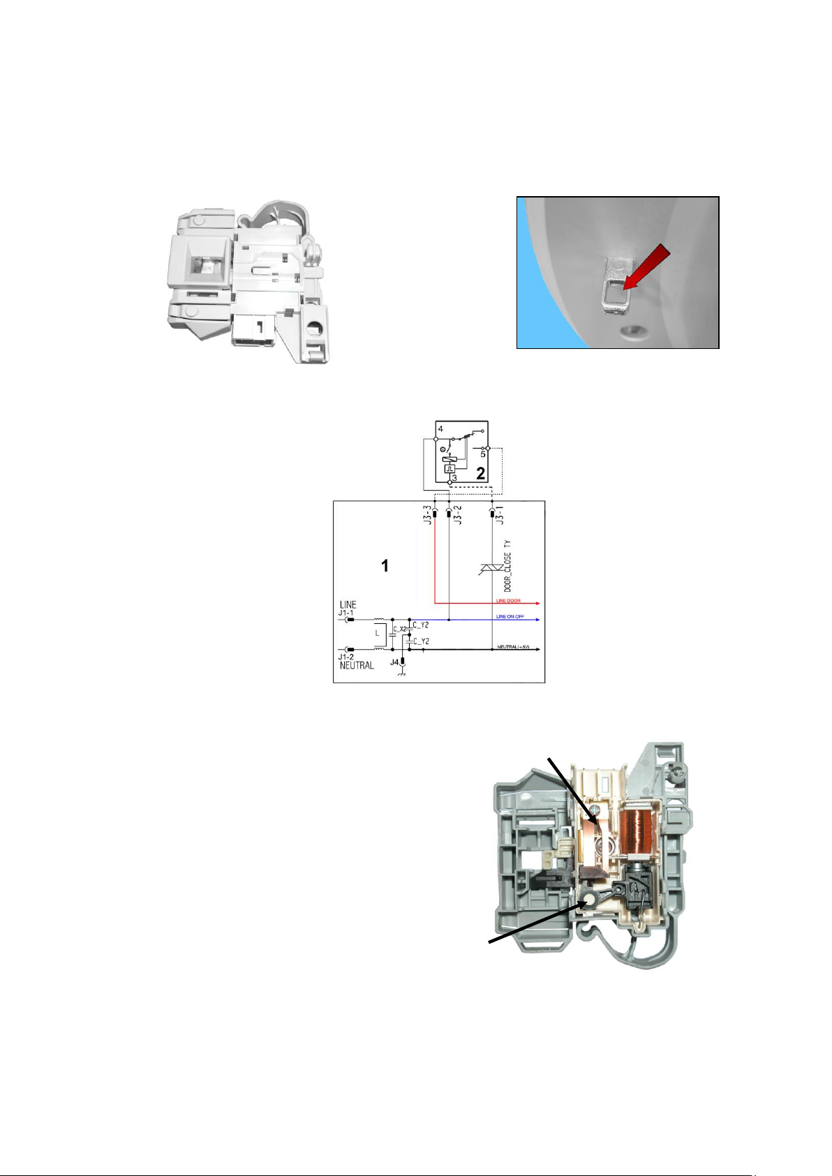
10.7 Door safety interlock PTO (Pull To Open)
1. Main electronic circuit board
2. Door safety interlock
2
6
1
5
3
4 7 8
9
10.7.1 General characteristics
This appliance is not fitted with a safety device featuring the traditional fastening latch which necessitated the
removal of the handle to open the appliance door.
The new safety device uses a new latch version with a hole in the middle, shown by the arrow (see figure) and you
pull the handle to open the appliance door.
The instantaneous door interlock allows the door to be opened as soon as the drum stops, if the conditions
described hereafter are met.
10.7.2 Operating principle
1. Solenoid protection PTC
2. Solenoid
3. Lifting assembly
4. Cam (with Labyrinth)
5. Locking pin
6. Electrical contacts (main switch)
7. Door sensing switch
8. Cursor
9. Manual opening
When the programme starts (start/pause button) the main circuit board sends a voltage pulse, lasting 20 msec.,
to the solenoid valve (2) (at least 6 seconds should have passed since turning it on), which moves the cam (4)
to a locking position; the blocking pin (5) is pushed, locking the cursor (8), which moves behind the ratchet (2)
to prevent it from turning, locking the latch inside the lock (see subsequent figures); simultaneously the main
switch contacts are shut (6).
Technical Support - MDM 38/84 599 78 10-24 Rev.01
Page 39
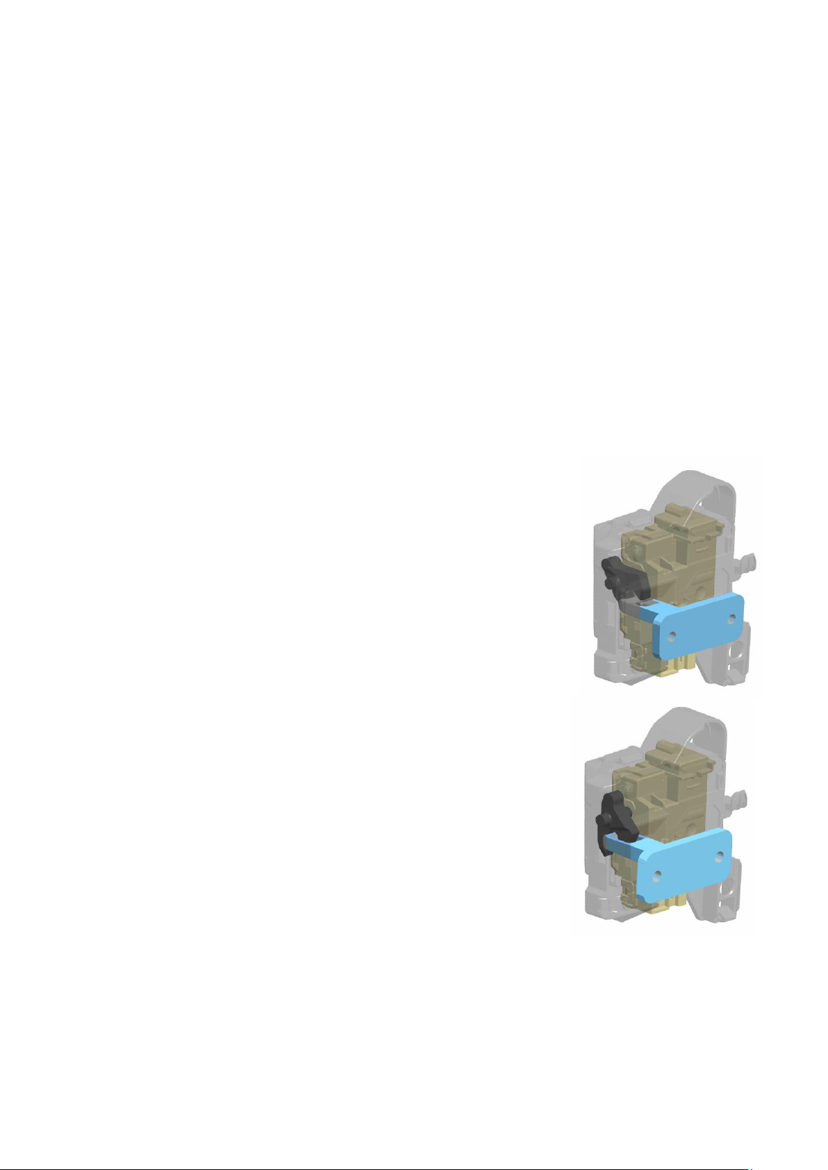
When the programme ends or the Start/Pause button is pressed, the circuit board sends two additional
1
2
1
2
20 msec pulses (200 msec apart):
The first pulse moves the cam (4) by another position, without releasing the pin (5).
The second pulse (which is only sent if everything is in working order) moves the cam (4) to another position,
which causes the pin (5) to return to its position and therefore release the interlock; the contacts of the main
switch are simultaneously opened.
Solenoid protection
A PTC is connected in series to the solenoid to limit the current (and therefore any overheating) in the following
cases:
main circuit board Triac short circuit
many consecutive pressings of the start/pause button (more than 5 times)
Appliance door/door open conditions
Before pulses are sent to release the door, the PCB checks for the following conditions:
The drum must be stationary.
The water level must not be higher than the lower edge of the door.
The temperature of the water must not be higher than 40º C.
10.7.2.1 Mechanical operation
1 Hake
2 Ratchet
When the appliance door closes, the latch (1) fits inside the ratchet (2).
Which, turning on itself, hooks onto and locks the ratchet in place.
If the appliance is switched off or paused and the appliance handle is pulled, the latch is released from the ratchet
(2), effortlessly, whereas if the START/PAUSE button has been pressed, the cursor (8) - being locked - does not
allow the ratchet to turn (2) so the fastening latch is locked for the entire wash cycle.
Technical Support - MDM 39/84 599 78 10-24 Rev.01
Page 40
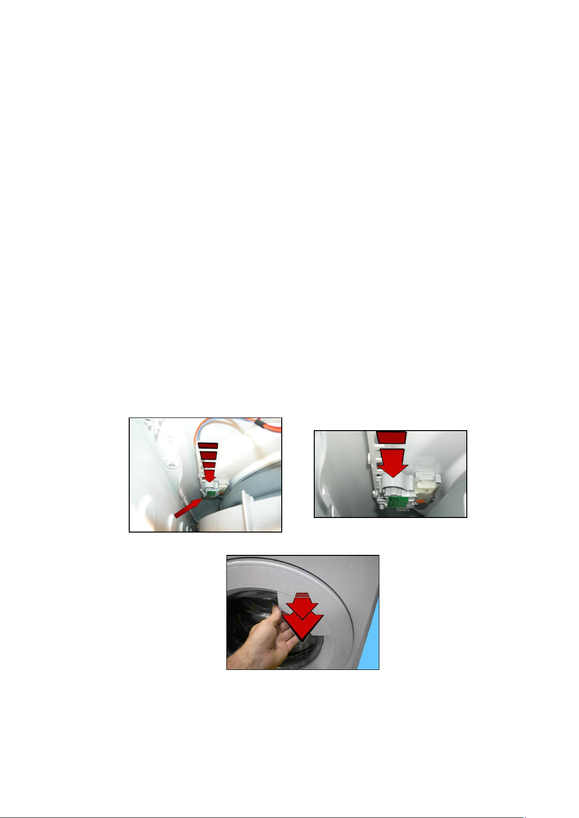
10.7.3 Manual opening of the appliance door:
Door safety
interlock
Previous instantaneous door safety interlocks released the lid automatically, in the following cases:
Power failure
The appliance being turned off at the ON/OFF button (before the wash cycle ended)
Whereas, in case of malfunction:
of the solenoid valve
main PCB faulty
the appliance had to be turned off to release the lid (by unplugging it from the mains supply).
Because inside they had a PTC bi-metal which allowed the lid to be opened after cooling, between 55 seconds and
4 minutes.
The new device (since it does not have a PTC) in the case of the above malfunctions is fitted with a manual
opening system, which allows the door to be opened following the instructions below:
Before proceeding with the manual opening of the appliance door, check:
1 That the drum is stationary.
2 If the water is above the lower level of the appliance door, drain off the water; if possible set a drainage
programme (see point 4) or unplug the appliance from the mains socket, disconnect the main drain pipe, lay it
on the ground and drain off the water (see point 5).
3 If the water is not above the lower level of the door, then it can be opened manually.
4 Unplug the appliance from the socket.
5 Activate the manual opening system.
To access the manual opening, proceed as follows:
Remove the worktop (see para. 50).
Press the plastic arch placed above the door safety device twice (shown by the dotted arrow) in order to trigger the
cam which leverages and releases the cursor to allow the latch to be removed from the ratchet.
Pull the handle
Technical Support - MDM 40/84 599 78 10-24 Rev.01
Page 41
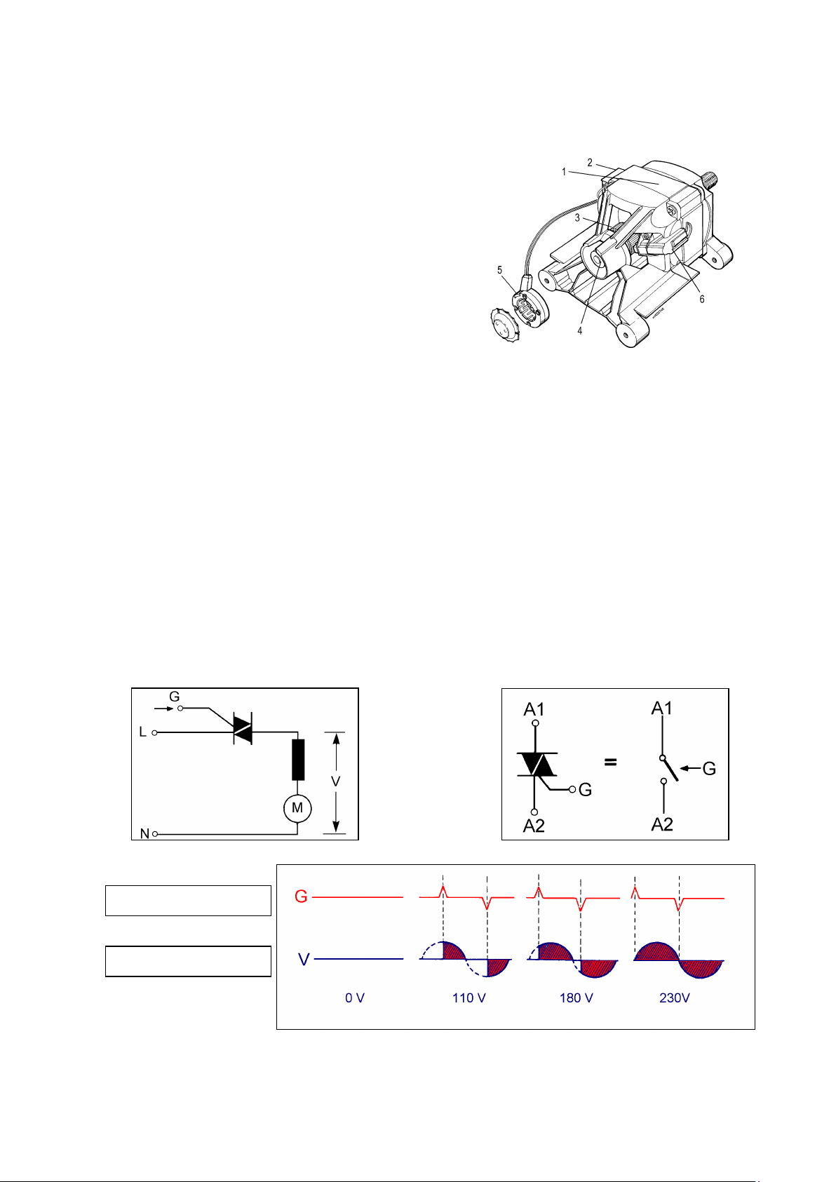
10.8 Universal motor
Starting pulses
Voltage on motor
10.8.1 General characteristics
Collector motors are fitted on appliances with a spin speed of between 600 and 1,600 rpm.
1. Stator
2. Terminal board
3. Collector
4. Tachometric generator magnet
5. Tachometric generator coil
6. Brush
10.8.2 Operating principle
The stator winding is connected in series to the rotor winding (serial excitation).
Every section of the rotor winding is connected to a pair of collector blades (also referred to as a switching device).
The electrical contact between the collector and the fixed circuit is made by two static brushes on the collector
blades.
The speed of rotation of the motor is proportional to the supply voltage, supplied by an electronic control.
This type of motor is also referred to as “universal” because it can be powered by either alternating or direct
current.
10.8.2.1 Motor speed control
This is achieved by an electronic control, by varying the voltage (V) applied to the motor.
The method adopted is the “phase partialization” command of the TRIAC. The TRIAC is an electronic
bidirectional switch. Closing of the circuit between A1-A2 (anodes) occurs when there are appropriate starting
pulses on gate (G).
Technical Support - MDM 41/84 599 78 10-24 Rev.01
Page 42
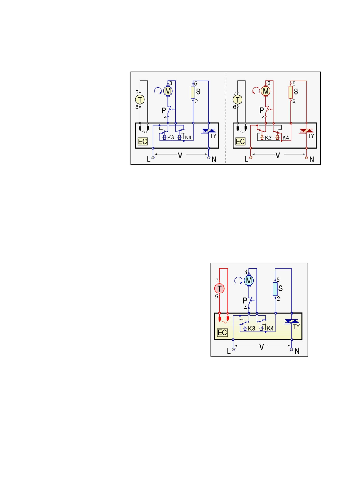
10.8.2.2 Direction of rotation of the motor
The direction of rotation of the motor depends on how the windings of the stator and rotor are connected to one
another. This connection is made by the circuit board relay contacts.
Clockwise rotation Anti-clockwise rotation
EC Electronic control
P Overheating cut-out (motor)
S Stator
M Rotor
T Tachometric generator
TY Triac
K3.4 Inversion relay
10.8.2.3 Tachometric generator
The speed of the collector motor, like all motors with serial excitation, depends on the load; so the speed
decreases as the load increases. This makes it necessary for the power supply voltage to the motor, and therefore
its speed, to be constantly controlled by an electronic speed control.
A tachometric generator, consisting of a magnet secured to the shaft and a coil, generates a voltage depending on
the speed of the rotor, which is sent to the electronic control.
All the electronic controls have a protection system, which is more or less sophisticated, to avoid the operation of
the motor in the event of a failure in the tachometric generator.
EC Electronic control
P Overheating cut-out (motor)
S Stator
M Rotor
T Tachometric generator
TY Triac
K3.4 Inversion relay
Technical Support - MDM 42/84 599 78 10-24 Rev.01
Page 43
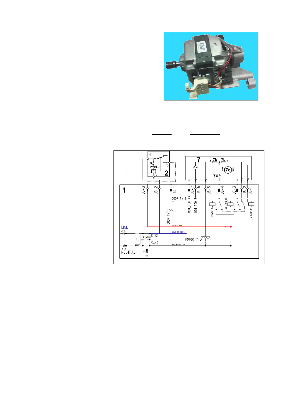
10.8.3 Power supply to motor
The PCB powers the motor via a TRIAC switch; the direction of rotation is reversed by switching the contacts on
the two relays (K1-K2), which modify the connection between the rotor and the stator.
In certain models, a third relay (K3) is used to power the stator (full or half field) according to the spin speed.
The motor speed is controlled by the signal from the tachometric generator.
During the spin phases, the micro-processor performs the anti-foam and the anti-balancing check procedure.
1. Main electronic circuit board
2. Door safety interlock
7. Universal motor
7a. Tachometric generator (motor)
7b. Stator (motor)
7c. Rotor (motor)
7d. Thermal cut-out (motor)
10.9 Anti-foam control system
The anti-foam control procedure is performed using the electronic pressure switch.
Spin with little foam: if the pressure switch senses a “full” level, the spin phase is interrupted, the drain pump
continues to operate and, when the pressure switch senses “empty”, the spin phase is resumed.
Spin with excess foam in the tub (critical situation): the control system detects whether the electronic
pressure switch switches 5 times to full (five spin interruptions). If this occurs, the spin phase is skipped, and a
one-minute drain cycle is performed with the motor stationary and, in the case of a washing phase, a
supplementary rinse is added.
Technical Support - MDM 43/84 599 78 10-24 Rev.01
Page 44
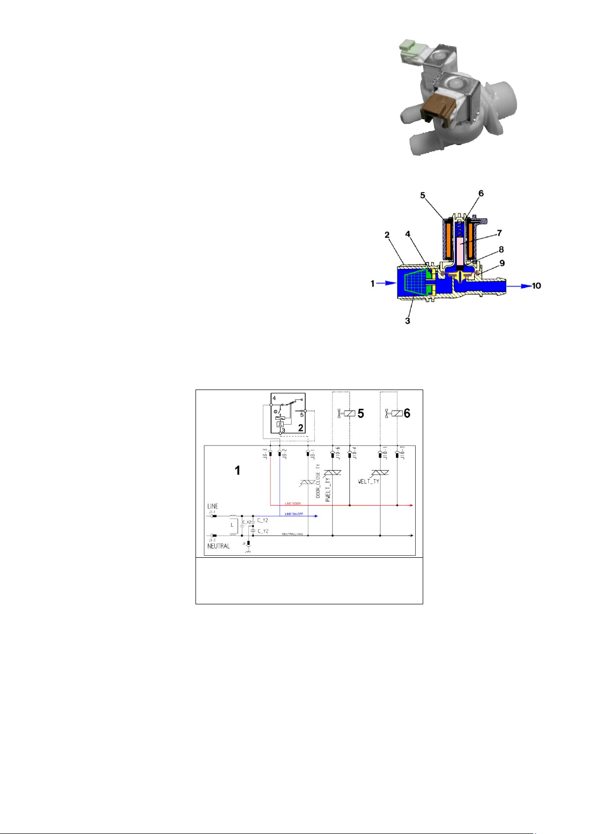
10.10 Solenoid valves
1. Main electronic circuit board
2. Door safety interlock
5. Pre-wash solenoid valve
6. Wash solenoid valve
10.10.1 General characteristics
This component introduces water into the detergent dispenser and is controlled electrically by the main circuit
board via Triac. The level of water in the tub is controlled by the analogue pressure switch.
1. Water inlet
2. Solenoid valve body
3. Filter or needle trap
4. Flow reducer
5. Coil
6. Spring
7. Moving core
8. Rubber
9. Membrane
10. Water outlet
10.10.2 Operating principle
When idle, the core, pushed by a spring, keeps the central hole of the membrane closed and so the latter
hermetically seals access to the water inlet duct.
When the coil is powered, the core is attracted, releasing the central hole of the membrane. Consequently the
valve opens.
10.10.3 Mechanical jamming of the solenoid valve
The solenoid valve may jam open without being actuated (which will cause flooding if the pressure switch
controlling the water level does not trip). If this occurs, the electronic control system (which continuously monitors
the flow sensor) will lock the door, start the drain pump and display an ALARM simultaneously.
10.10.4 Low water pressure
If the flow sensor does not generate a signal during the water fill phases, even though power is being supplied to
the solenoid valve, the cause of this condition may be a closed water tap or clogged filter on the solenoid valve
(with ensuing low water pressure). If this occurs, only a WARNING will be displayed and the cycle will continue for
five minutes, after which time an ALARM will be signaled.
Technical Support - MDM 44/84 599 78 10-24 Rev.01
Page 45
Alarm
Description
Possible fault
Machine status/action
Reset
E00
No alarm
E11
Water fill difficulty during washing
Tap closed or water pressure too low; Drain pipe improperly
positioned; Water fill solenoid valve faulty; Leaks from water circuit on
pressure switch; Pressure switch faulty; Wiring faulty; Main PCB
faulty.
Cycle is paused with door locked
START/RESET
E13
Water leaks
Drain pipe improperly positioned; water pressure too low
Water fill solenoid valve faulty; Water circuit on pressure switch is
leaking/clogged; Pressure switch faulty.
Cycle is paused with door locked
START/RESET
E21
Drain difficulty during washing
Drain pipe kinked/clogged/improperly positioned; Drain filter
clogged/dirty; Wiring faulty; Pressure switch faulty; Drain pump rotor
blocked; Drain pump faulty; Main PCB faulty.
Cycle is paused
(after 2 attempts)
START
ON/OFF
RESET
E23
Faulty triac for drain pump
Wiring faulty; drain pump faulty; main PCB faulty.
Safety drain cycle - Cycle stops with
door open.
RESET
E24
Drain pump TRIAC “sensing” circuit
faulty.
Main circuit board faulty.
Safety drain cycle - Cycle stops with
door unlocked.
RESET
E25
Aqua Control “sensing” circuit faulty
Main circuit board faulty.
Safety drain cycle - Cycle stops with
door unlocked.
RESET
E31
Electronic pressure switch circuit
faulty
Wiring; Electronic pressure switch; Main PCB;
Cycle stops with door locked
RESET
E32
Calibration error of the electronic
pressure switch
Drain tube kinked/clogged/improperly positioned; Faulty solenoid;
Drain filter clogged/dirty; Drain pump faulty; Leaks in the pressure
switch hydraulic circuit; Pressure switch faulty;
Wiring; main PCB;
Cycle is paused
START/RESET
E35
Overflow
Water fill solenoid valve faulty; Leaks from water circuit on pressure
switch; Wiring faulty; Pressure switch faulty; Main PCB faulty.
Cycle interrupted. Safety drain cycle.
Drain pump continues to operate (5 min.
on, then 5 min. off. etc.)
RESET
E38
Internal pressure chamber is
clogged (water level does not
change for at least 30 sec. of drum
rotation)
Motor belt broken; Water circuit on pressure switch clogged.
Heating phase is skipped
RESET
E41
Door open
Check whether the door is closed properly;
Wiring faulty; door safety interlock faulty;
Main circuit board faulty.
Cycle is paused
START/RESET
E42
Problems with door lock
Wiring faulty; door safety interlock faulty;
Electrical current leak between heating element and ground; Main
PCB faulty.
Cycle is paused
START/RESET
E43
Faulty triac supplying power to door
delay system
Wiring faulty; door safety interlock faulty;
Main circuit board faulty.
(Safety drain cycle)
Cycle blocked
RESET
E44
Faulty “sensing” by door delay
system
Main circuit board faulty.
(Safety drain cycle)
Cycle blocked
RESET
11 ALARM SUMMARY TABLE
Technical Support - MDM 45/84 599 78 10-24 Rev.01
Page 46
Alarm
Description
Possible fault
Machine status/action
Reset
E45
Faulty “sensing” by door delay
system triac
Main circuit board faulty.
(Safety drain cycle)
Cycle blocked
RESET
E51
Motor power triac short-circuited
Current leakage from motor or from wiring; Main PCB faulty;
Cycle stops with door open
(after 5 attempts)
ON/OFF
E52
No signal from motor tachometric
generator
Wiring faulty; Motor faulty;
Main board faulty;
Cycle stops with door locked
(after 5 attempts)
ON/OFF
RESET
E53
Faulty “sensing” by motor triac
Main circuit board faulty.
Cycle blocked
RESET
E54
Motor relay contacts sticking
Current leakage from motor or from wiring; Main PCB faulty;
Cycle blocked
(after 5 attempts)
RESET
E61
Insufficient heating during washing
Wiring faulty; NTC probe for wash cycle faulty; Heating element
faulty; Main PCB faulty.
The heating phase is skipped
START/RESET
E62
Overheating during washing
(temperature higher than 88°C for
more than 5 min.)
Wiring faulty; NTC probe for wash cycle faulty; Heating element
faulty; Main PCB faulty.
Safety drain cycle
Cycle stops with door open
RESET
E66
Heating element power relay faulty
(inconsistency between sensing and
relay status)
Earth leakage between heating element and earth.
Main PCB faulty;
Safety water fill
Cycle stops with door closed.
ON/OFF
RESET
E68
Earth leakage
Earth leakage between heating element and earth.
The heating phase is skipped
START/RESET
E69
Heating element interrupted
Wiring faulty; Heating element for washing interrupted (thermal fuse
open); Main PCB faulty.
----------------
START
ON/OFF
RESET
E6A
Heating relay sensing faulty
Main circuit board faulty.
Cycle stops with door locked
RESET
E6H
Heating element power relay faulty
(inconsistency between sensing and
relay status)
Wiring faulty; Earth leakage between heating element and earth; Main
PCB faulty.
Safety water fill
Cycle stops with door closed.
ON/OFF
RESET
E71
NTC probe for wash cycle faulty
(short-circuited or open)
Wiring faulty; NTC probe for wash cycle faulty
Main circuit board faulty.
The heating phase is skipped
START/RESET
E74
NTC probe for wash cycle
improperly positioned
Wiring faulty; NTC probe for wash cycle improperly positioned; NTC
probe faulty; Main PCB faulty.
The heating phase is skipped
RESET
E84
Recirculation pump triac “sensing”
circuit faulty.
Main circuit board faulty.
Safety drain cycle - Cycle stops with
door open.
RESET
E85
Circulation pump TRIAC switch
faulty
Wiring faulty; recirculation pump faulty; main PCB faulty.
Safety drain cycle - Cycle stops with
door open.
RESET
E87
Display board microprocessor faulty
If this continues, replace the display board
No action to be taken
START
ON/OFF
RESET
E91
Communication error between main
PCB and display
Wiring faulty; control/display circuit board faulty, Inverter Board faulty,
Main circuit board faulty.
----------------
RESET
E92
Communication inconsistency
between main PCB and display
(incompatible versions)
Incorrect control/display PCB
Incorrect PCB (does not correspond to the model).
Cycle blocked
ON/OFF
Technical Support - MDM 46/84 599 78 10-24 Rev.01
Page 47
Alarm
Description
Possible fault
Machine status/action
Reset
E93
Appliance configuration error
Main PCB faulty (incorrect configuration data)
Cycle blocked
ON/OFF
E94
Incorrect configuration of washing
cycle
Main PCB faulty (incorrect configuration data)
Cycle blocked
ON/OFF
E97
Inconsistency between programme
selector and cycle configuration
Main PCB faulty (incorrect configuration data).
Cycle blocked
RESET
E9C
Display board configuration error
Display board faulty
----------------
START
ON/OFF
RESET
E9E
Display board sensor/touch key
faulty
Display board faulty
----------------
ON/OFF
EC1
Electronically controlled valve
blocked with operating flowmeter
Faulty wiring; Faulty/blocked solenoid, PCB faulty,
Cycle stops with door locked
Drain pump continues to operate (5 min.
on, then 5 min. off. etc.)
RESET
EC4
AGS current sensor faulty.
Main board faulty.
Spin speed reduced to safety speed of
150 rpm
RESET
EF1
Drain filter clogged
(drain phase too long)
Drain filter clogged/dirty.
Drain hose blocked/kinked/too high.
Warning displayed at the end of cycle.
START/RESET
EF2
Overdosing of detergent
(too much foam during drain
phases)
Excessive detergent dosing; Drain hose kinked/blocked;
Drain filter clogged/dirty.
Warning displayed after 5 attempts or
by the specific LED.
RESET
EF3
Aqua control system intervention
Water leaks onto base frame; Aqua control system faulty;
Drain pump coil overheating/broken.
Appliance drain
ON/OFF RESET
EF4
Water fill pressure too low, no signal
from flowmeter and electronically
controlled valve is open
Tap closed, water fill pressure too low
----------------
RESET
EF5
Unbalanced load
Final spin phases skipped.
----------------
START/RESET
EF6
Reset
If it continues, replace the main board.
No action to be taken
----------------
EH1
Appliance power supply frequency
out of limits
Problem with the power supply network (incorrect/disturbed); Main
PCB faulty.
Wait for nominal
frequency conditions
ON/OFF
EH2
Supply voltage too high
Problem with the power supply network (incorrect/disturbed); Main
PCB faulty.
Wait for nominal
voltage conditions.
ON/OFF
EH3
Supply voltage too low
Problem with the power supply network (incorrect/disturbed); Main
PCB faulty.
Wait for nominal
voltage conditions.
ON/OFF
Technical Support - MDM 47/84 599 78 10-24 Rev.01
Page 48
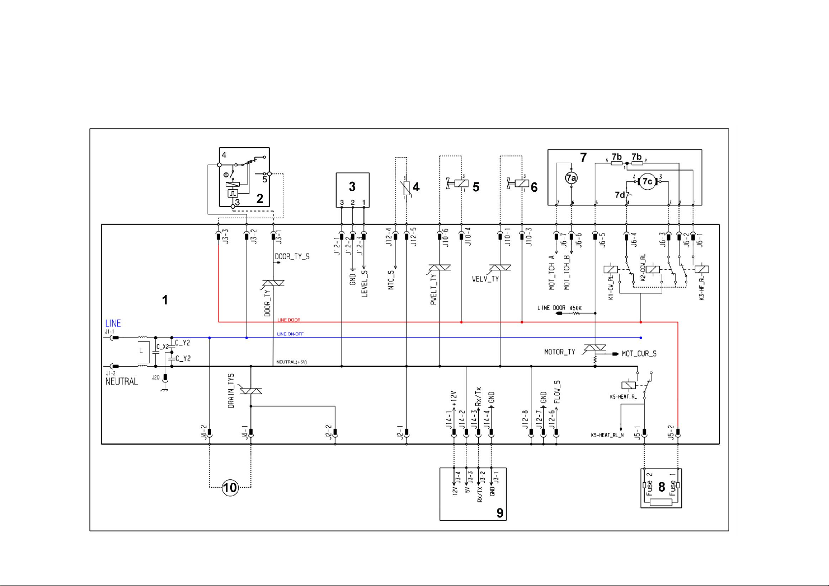
12 DIAGRAMS
12.1 EWX13611 Operating Circuit Diagram
Technical Support - MDM 48/84 599 78 10-24 Rev.01
Page 49
Appliance electrical components
PCB components
1 Main electronic circuit board
2 Door safety interlock
3 Electronic pressure switch
4 NTC
5 Pre-wash solenoid valve
6 Wash solenoid valve
7 Universal motor
7a. Tachometric (motor)
7b. Stator (motor)
7c. Rotor (motor)
7d. Thermal cut-out (motor)
8. Heating element
9. Display board
10. Drainage pump
DRAIN_TYS Drain pump Triac
DOOR_TY Door interlock Triac
PWELT_TY Pre-wash solenoid Triac
WELV_TY Wash solenoid Triac
MOTOR TY Motor Triac
K1 Clockwise rotation motor relay
K2 Anti-clockwise rotation motor relay
K3 Spin speed motor relay
K5 Heating element relay
12.2 EWX13611 Operating circuit diagram key
Technical Support - MDM 49/84 599 78 10-24 Rev.01
Page 50
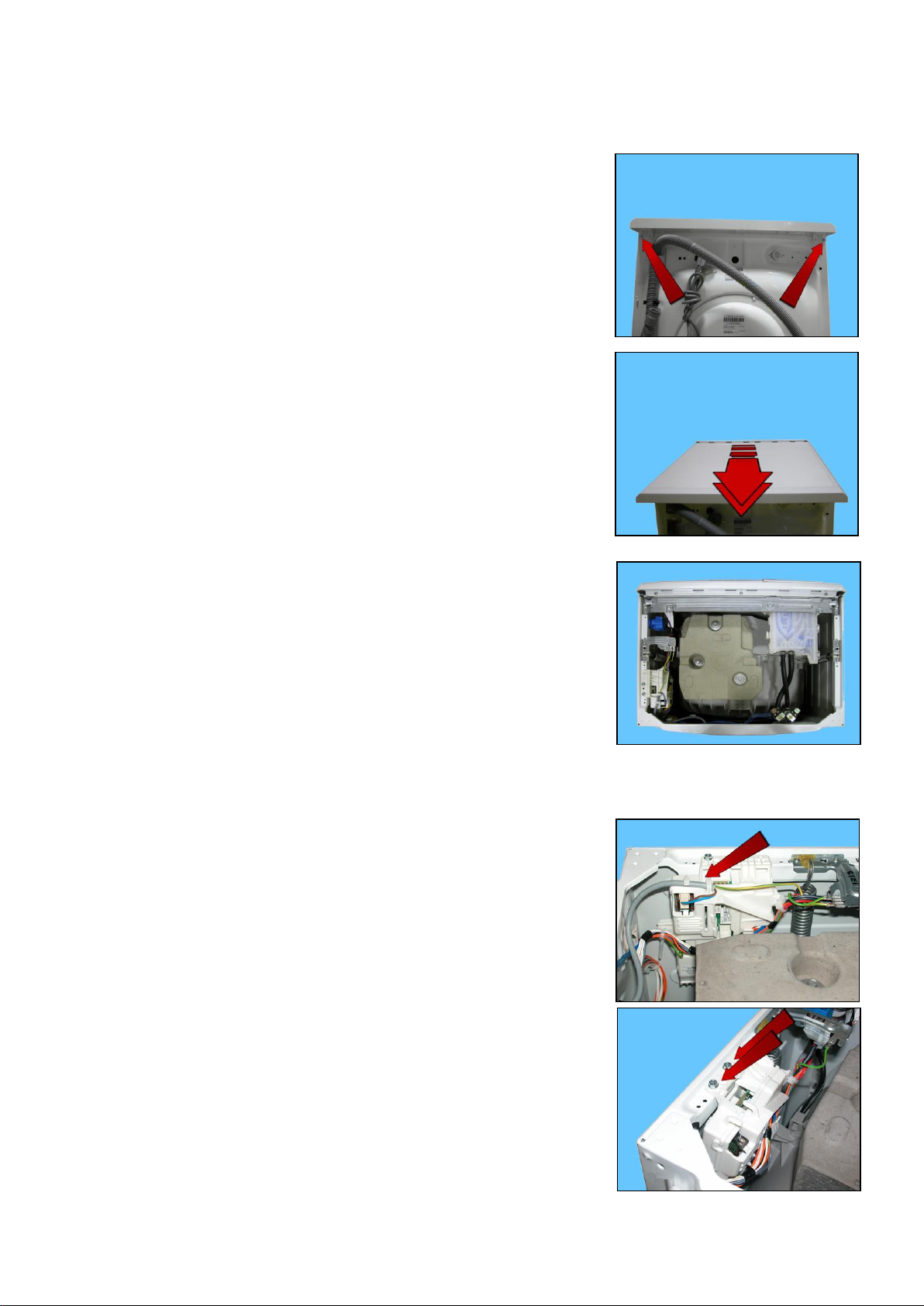
1 2 3 4 5
6
7
13 ACCESS
Make sure you wear gloves, because parts of the cabinet are sharp
13.1 Worktop
Remove the screws that secure it to the back panel.
Pull it out from the back
13.2 From the worktop, you can access
1. Main board
2. Solenoid valve
3. Display board/light diffuser/buttons/buttons springs assembly
4. Control panel
5. Analogue pressure switch
6. Detergent dispenser
7. Upper counterweight
13.2.1 Main board
To service the main board, use the antistatic kit a code 4055063-95/4
Remove the worktop (see relevant paragraph).
Remove the power cable from the hooks that hold it close to the board.
Slide off the connector
Unfasten the two screws securing it to the cabinet
Technical Support - MDM 50/84 599 78 10-24 Rev.01
Page 51
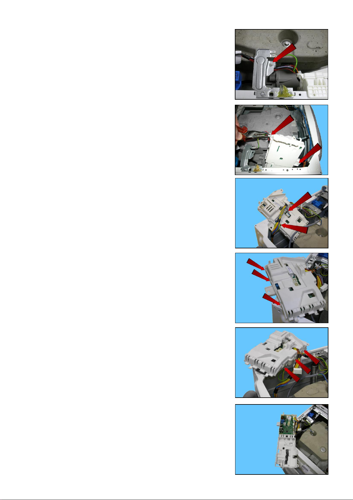
Remove the clamp that secures the wiring to the spring support bracket.
Using a pair of pliers, remove the clamps that secure the wiring to the power
board assembly container (indicated by the arrows)
Position the board assembly as shown in the figure
Remove the connectors and the faston that connects the earth (beware as it is
fitted with an anti-sliding stop).
Remember to use the anti-sliding kit
Unhook the three hooks that join the two casings on one side.
And on the other
Lift the lid
Technical Support - MDM 51/84 599 78 10-24 Rev.01
Page 52
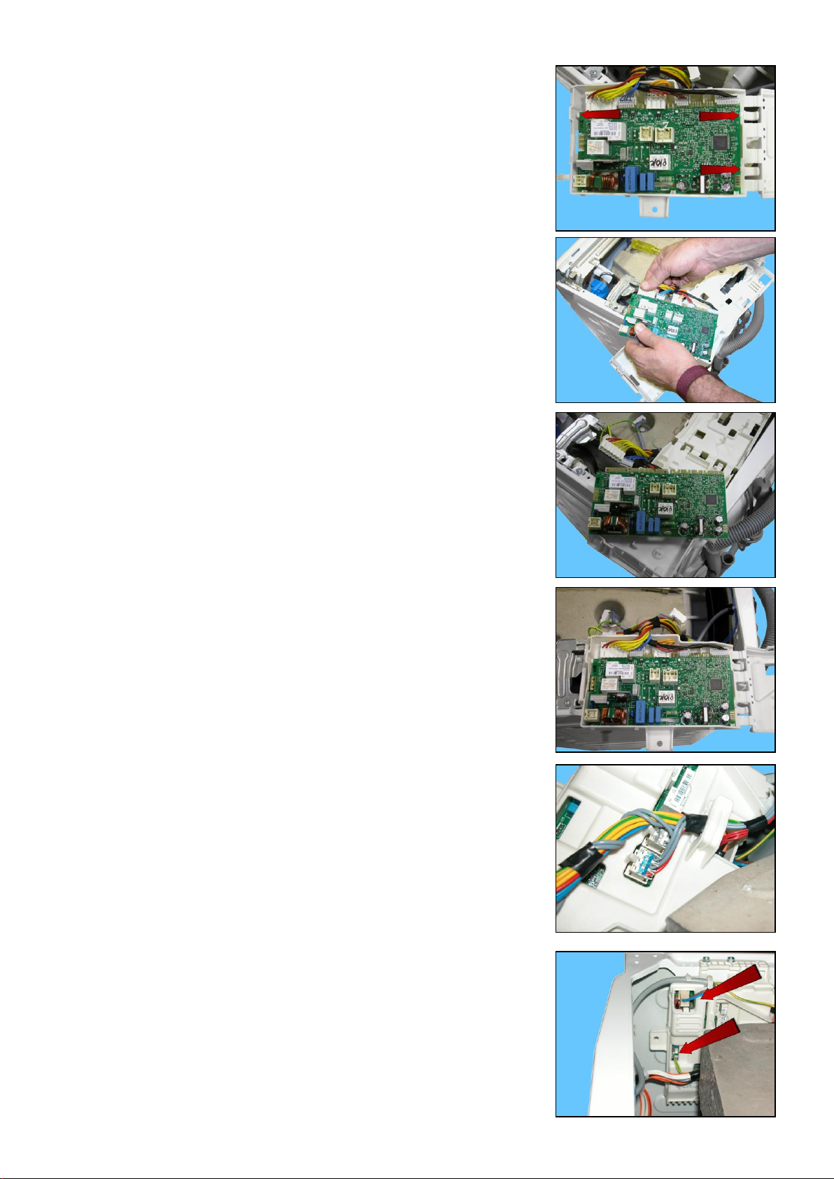
Release the three hooks that secure the board to the container and remove it
(take care not to break the hooks)
Remove the connectors
Board
When reassembling
Once you have inserted the connectors, make sure the wiring is inside the box.
So that when the lid is closed, the wiring is not crushed or cut by the two plastic
parts.
Fit the connectors into their proper slots and arrange the wiring as shown in
the figure
Before securing the side clamp:
Restore the earth connection, fit the power supply connector
And insert it between the two hooks
Technical Support - MDM 52/84 599 78 10-24 Rev.01
Page 53
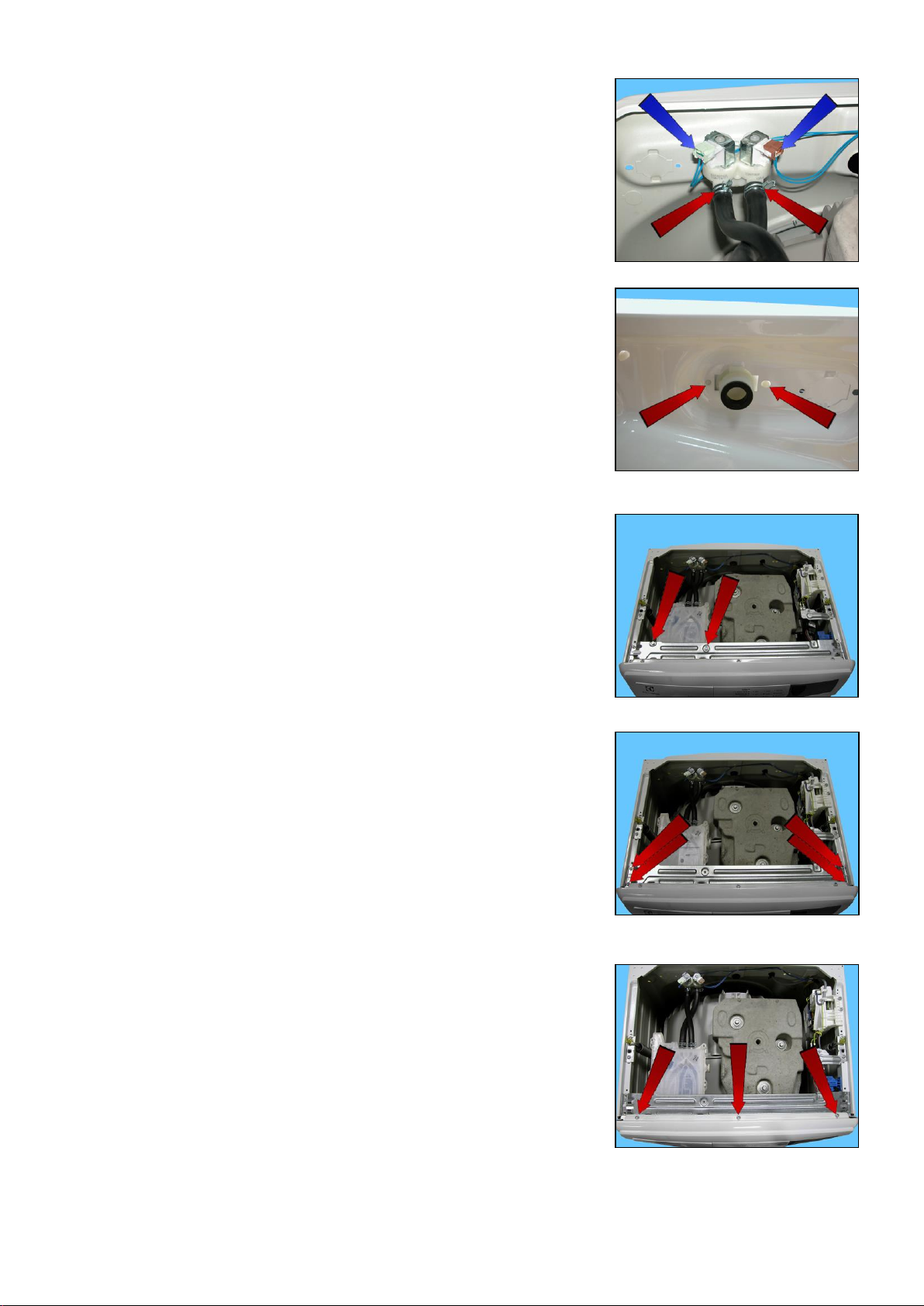
13.2.2 Solenoid valve
Remove the worktop (see relevant paragraph).
Detach the connectors indicated by the blue arrows.
Pull out the pipes indicated by the red arrows, which connect the solenoid
valve to the detergent dispenser.
Unscrew the water fill pipe from the solenoid valve.
Push the two retainers indicated by the arrows towards the inside of the
appliance.
At the same time, turn the solenoid valve to remove it.
13.2.3 Display board assembly
Remove the worktop (see relevant paragraph).
Remove the two screws securing the detergent drawer to the control crosspiece
Loosen the screws which secure the control crosspiece to the cabinet
Loosen the screws which secure the front panel to the control crosspiece
Technical Support - MDM 53/84 599 78 10-24 Rev.01
Page 54
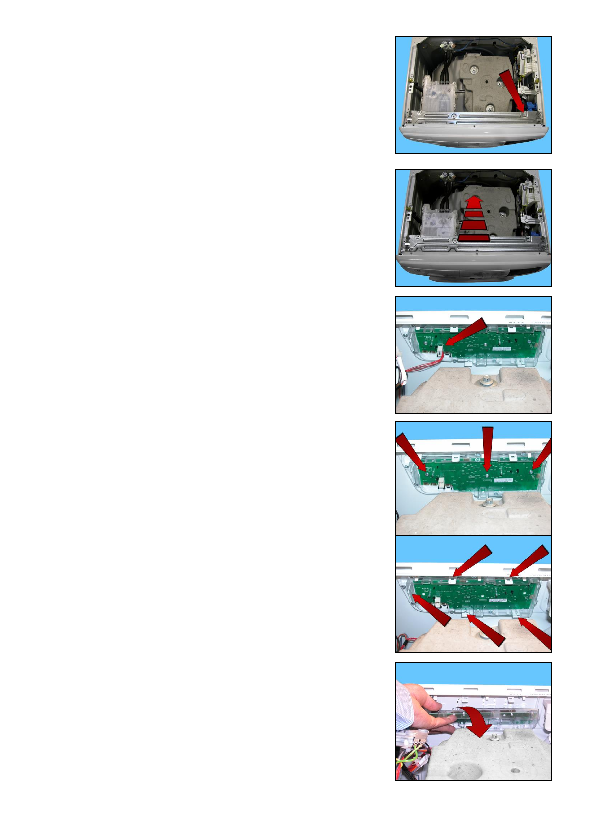
Remove the clamp that secures the wiring
Remove the crosspiece
Disconnect the connector.
Using a small cross-head screwdriver, loosen the three screws (shown by the
arrows) securing the display board assembly to the control panel.
Delicately release the hooks which secure the display board to the control
panel, taking care not to break them.
Start with the top ones and work anti-clockwise, continuing with the side one
and lastly the bottom ones.
Turn the display board assembly and remove it
Technical Support - MDM 54/84 599 78 10-24 Rev.01
Page 55
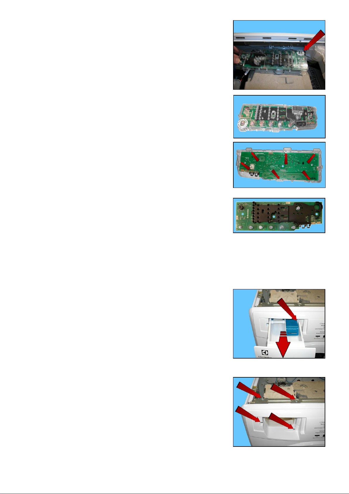
1 1 2
2
Make sure the ON/OFF button spring (shown by the arrow) does not fall into the
appliance.
Display board assembly
To remove the display board from its protection, pull it out of the hooks shown
by the arrows in the figure.
Display board
13.2.4 Control panel
Remove the worktop (see relevant paragraph).
Take out the detergent dispenser while at the same time pressing on its sides
to pull it out (otherwise pull sharply).
Unfasten the two screws securing it to the control panel (1).
Unfasten the two screws securing it to the crosspiece (2).
When reassembling, repeat these steps in the reverse order.
Tighten the screws that secure it to the control panel at a torque of 2.5 Nm.
Move the detergent dispenser towards the inside of the appliance
Technical Support - MDM 55/84 599 78 10-24 Rev.01
Page 56
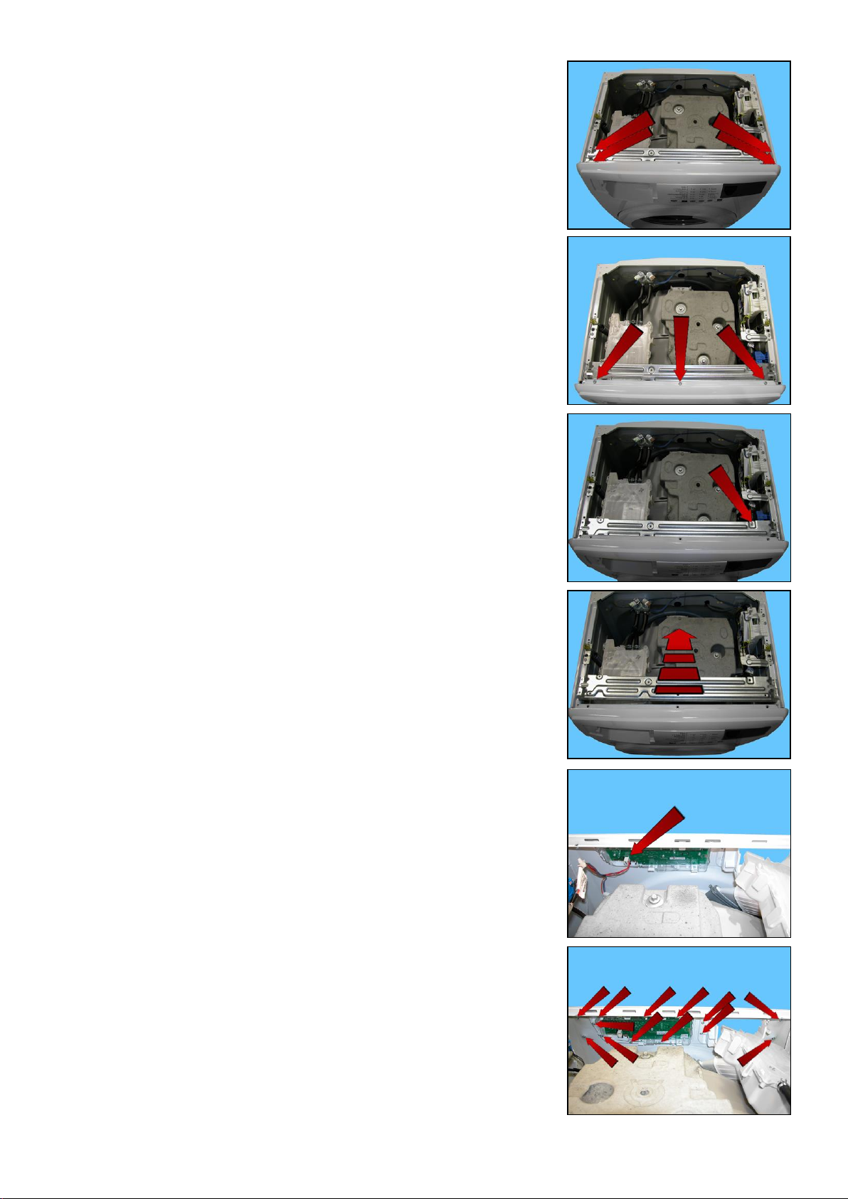
Loosen the screws which secure the control crosspiece to the cabinet
Loosen the screws which secure the front panel to the control crosspiece
Remove the clamp that secures the wiring.
Remove the crosspiece
Disconnect the connector.
Using a small cross-head screwdriver, loosen the screws (shown by the
arrows) securing the control panel to the front panel.
Release the hooks that secure the control panel to the front panel, which are
situated beside the screw seats (except for the screws in the middle of the
control panel)
Technical Support - MDM 56/84 599 78 10-24 Rev.01
Page 57
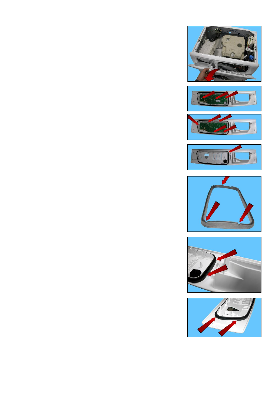
Extract the control panel.
Remove the three screws which secure the display board assembly to
the control panel.
Release the hooks securing the display board assembly to the control panel.
On the control panel, a small wall has been created around the display board
seat. It is surrounded by a seal, which prevents any water seepage from coming
into contact with the display board itself.
When reassembling:
The seal features some references: two on one side and one on the other.
Place the side of the seal with the two references opposite the two references
on the control panel.
Make sure the seal is correctly positioned from the opposite side as well.
Technical Support - MDM 57/84 599 78 10-24 Rev.01
Page 58
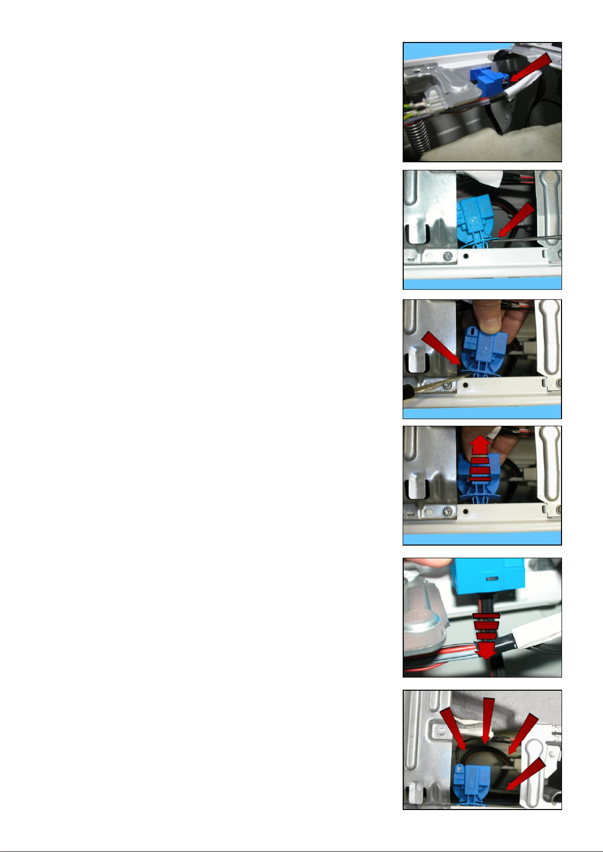
13.2.5 Analogue pressure switch
Remove the worktop (see relevant paragraph).
Remove the connector (red arrow)
Tighten the tabs which secure it to the cabinet, first on one side.
Then on the other.
Take it out
Pull out the small tube which connects it to the pressure chamber.
When reassembling the pressure switch, repeat these steps in the reverse order.
arrange the pipe as shown in the figure, making sure it does not touch the
counterweight and position it in its purpose-provided seats incorporated into
the welded tub (shown by the arrows). To prevent the pipe from coming into
contact with the unit while the appliance is in operation.
Technical Support - MDM 58/84 599 78 10-24 Rev.01
Page 59
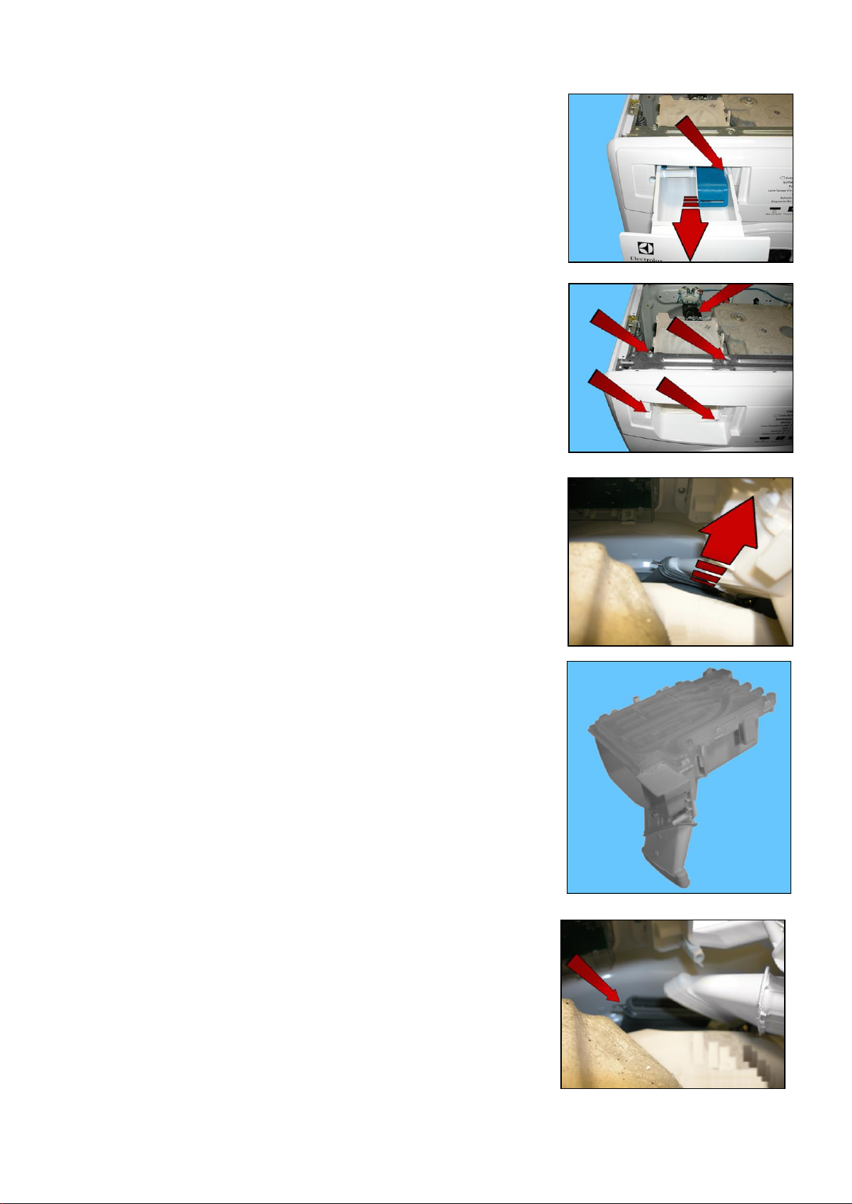
1 1 2
2
3
13.2.6 Detergent dispenser
Remove the worktop (see relevant paragraph).
Take out the detergent dispenser while at the same time pressing on its sides
to pull it out (otherwise pull sharply).
Unfasten the two screws securing it to the control panel (1)
Unfasten the two screws securing it to the crosspiece (2)
Remove the pipes that connect it to the solenoid valve (3).
When reassembling, repeat the same steps in the reverse order and tighten the
screws that secure it to the control panel at a torque of 2.5 Nm.
Pull out the detergent dispenser from the bellows seal detergent inlet pocket.
Detergent dispenser
When reassembling
If the clamp was removed, reposition it in its seat (shown by the arrow) in the
bellow seal detergent inlet pocket.
Technical Support - MDM 59/84 599 78 10-24 Rev.01
Page 60
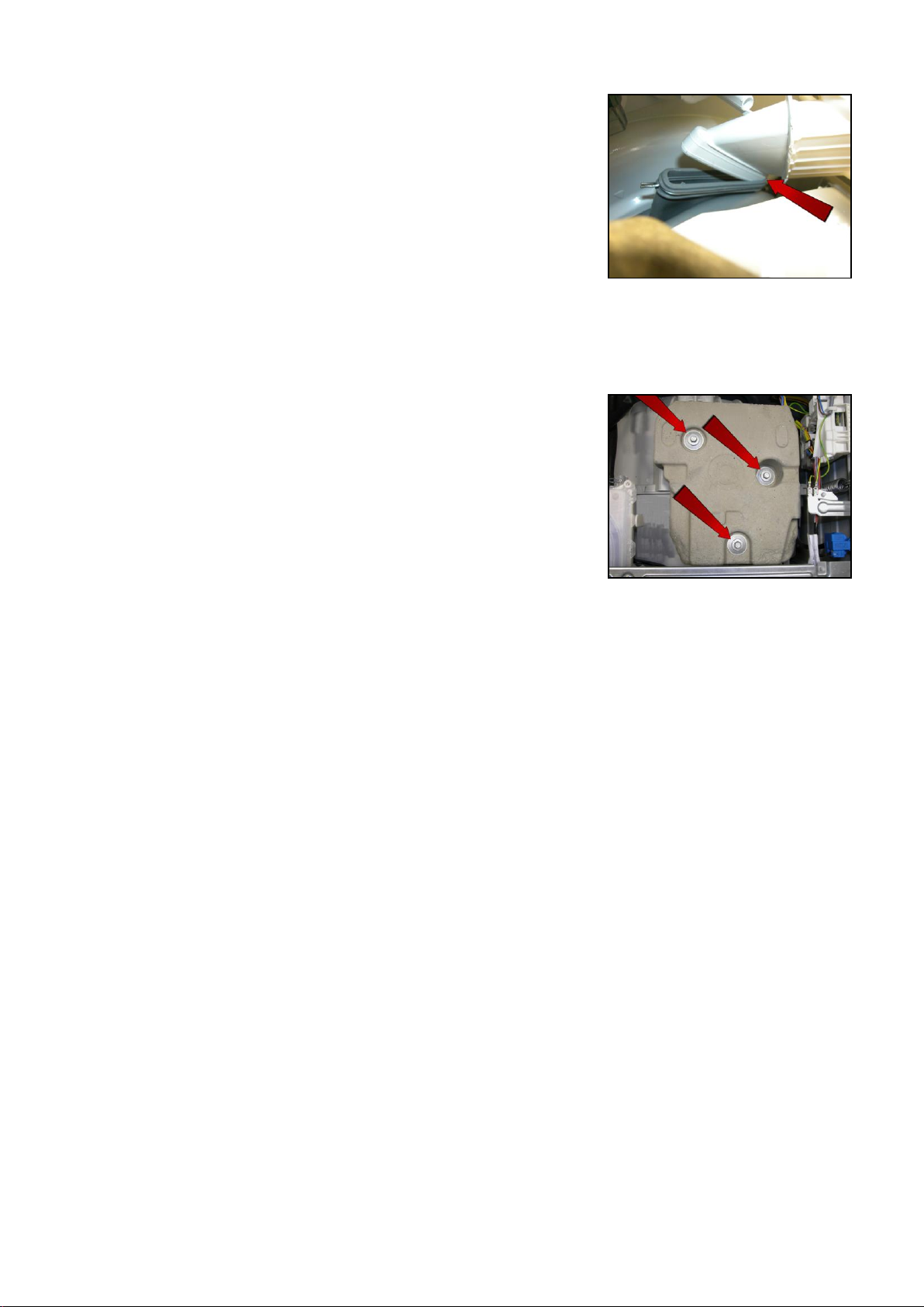
Lubricate the outside of the detergent dispenser
Lubricate the inside of the bellow seal detergent inlet pocket.
First task to perform:
Gently insert the part of the detergent dispenser indicated by the arrow into the
detergent inlet pocket of the bellows seal.
Second task:
With one hand inside the appliance door, hold the bellow seal detergent inlet pocket still and gently insert the rest of
the detergent dispenser
13.2.7 Upper counterweight
Remove the worktop (see relevant paragraph).
Remove the three screws that secure it to the welded tub
The counterweight weighs 9.7 kg
When reassembling:
If the tub assembly is new, tighten the screws at a torque of 20 Nm.
If the tub assembly is new, tighten the screws at a torque of 15 Nm.
Technical Support - MDM 60/84 599 78 10-24 Rev.01
Page 61
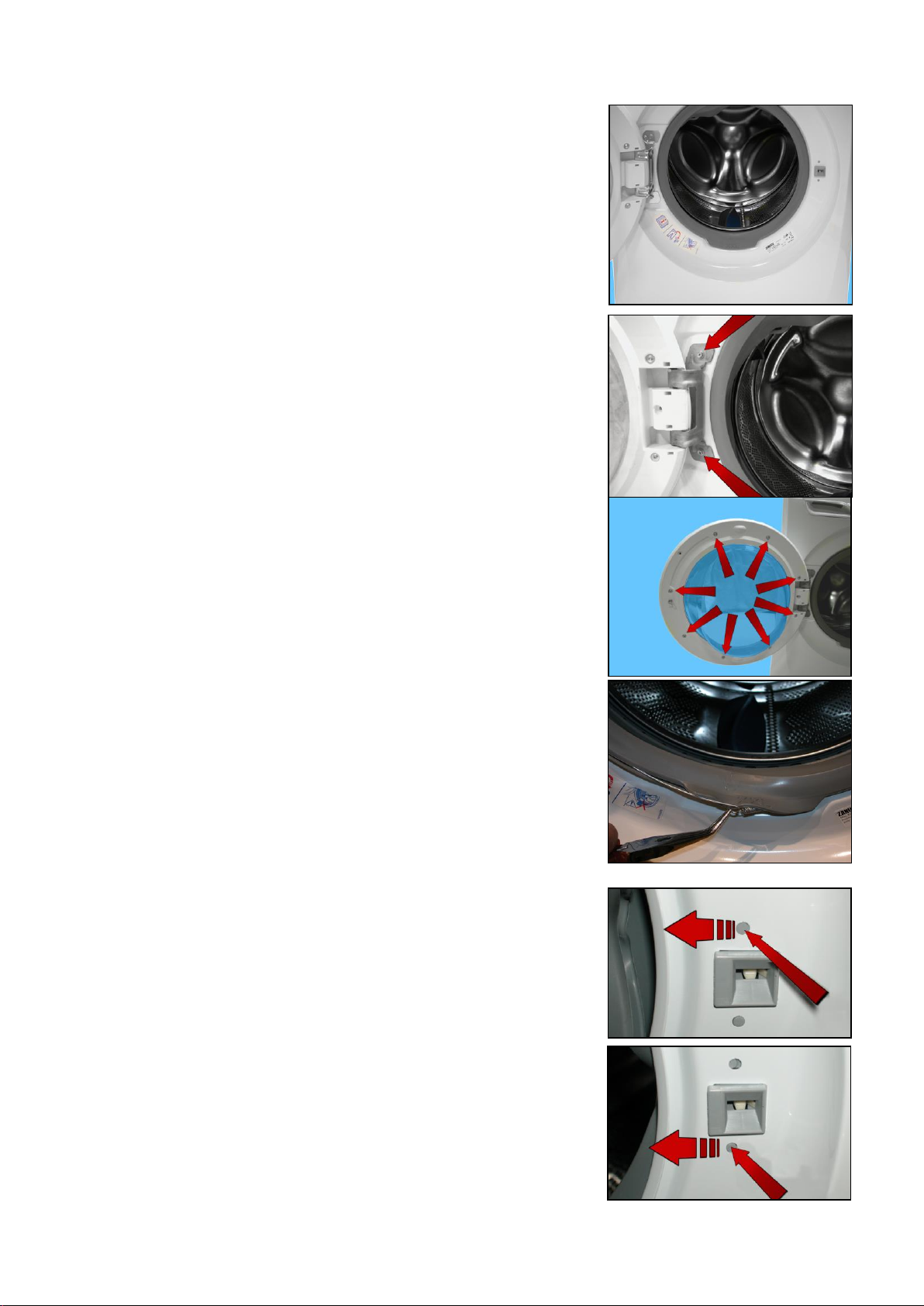
1 2 3
4
13.3 Accessing the front part
1. Door and Door Hinge
2. Door safety interlock
3. Blade
4. Front panel
13.3.1 Door hinge - Door
To replace the hinge, loosen the screws securing it to the cabinet.
To access the door, loosen the screws joining the two front and rear door
frames together.
13.3.2 Door safety interlock
Remove the iron ring securing the bellow seal to the unit.
Remove the part of the bellow seal concerned from the cabinet.
Take care not to scratch the cabinet.
Push the pin at the top inwards and at the same time move the door safety
device towards the left
Holding the top still
Push the pin at the bottom inwards and at the same time move the door safety
device towards the left
Technical Support - MDM 61/84 599 78 10-24 Rev.01
Page 62
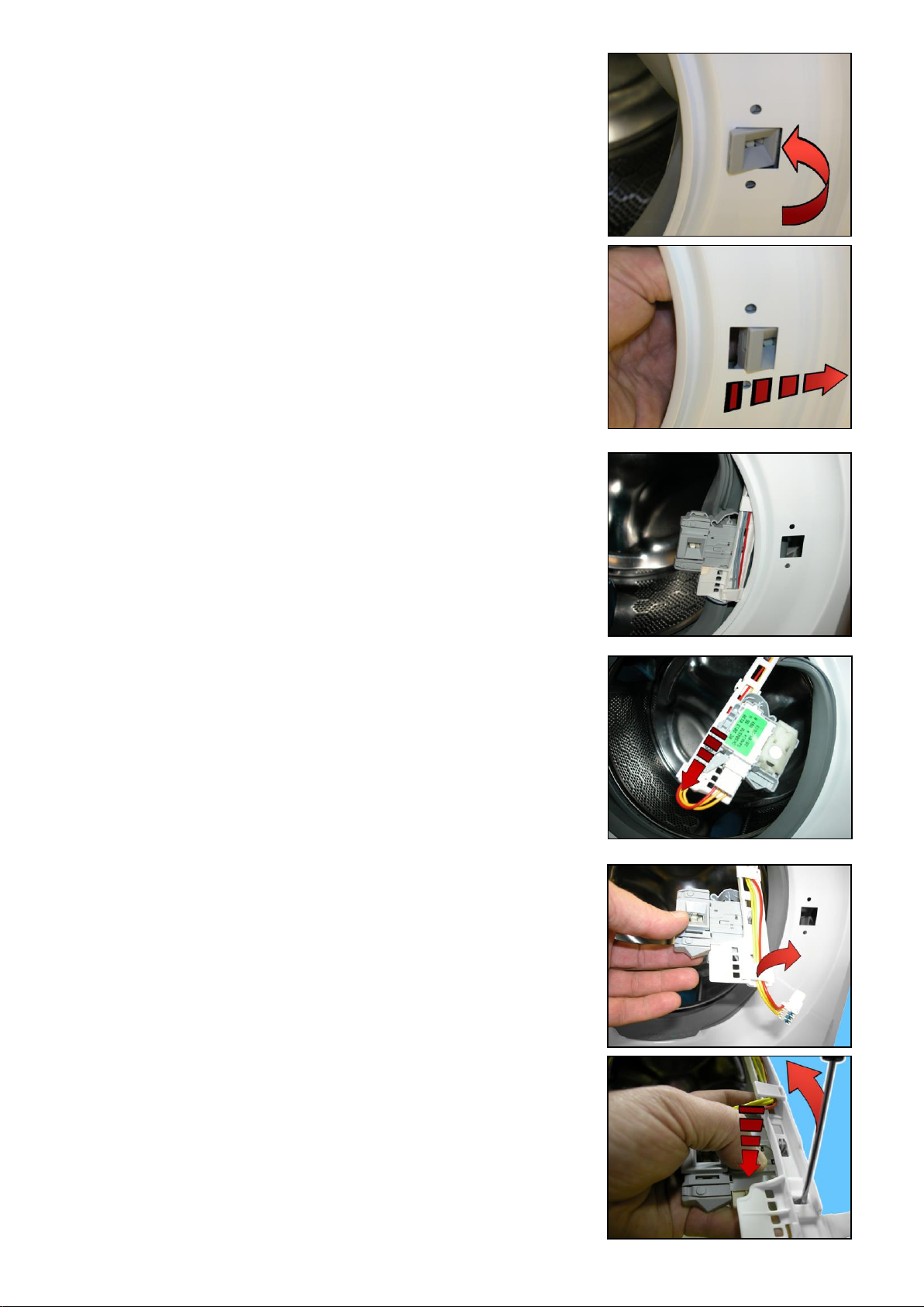
Turn it towards the inside (right-hand side of the flange).
Pull it out and remove it.
remove it
Pull a little of the wiring out of the protection and remove the connector
Release the hook, remove the wiring and move it.
Insert a flat-tip screwdriver into the slot near the hook
Tilt it in the direction of the arrow so as to release it from the latch, while at the
same time pushing the micro-switch with your thumb in the direction shown by
the arrow
Technical Support - MDM 62/84 599 78 10-24 Rev.01
Page 63
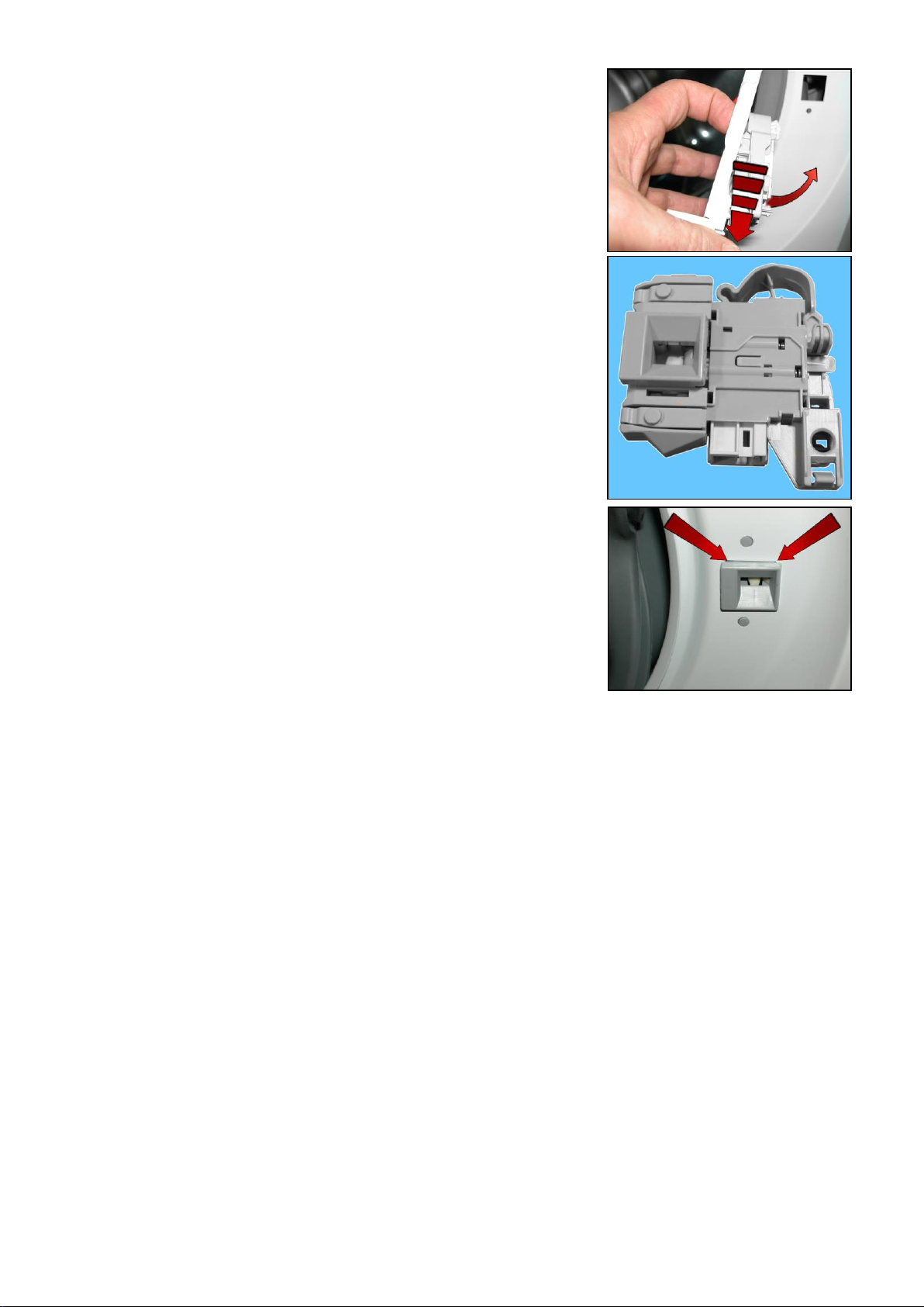
After releasing it from the latch which secured it to the protection
Move it in the direction shown by the dotted arrow and turn it in order to
remove it.
Safety device
To reassemble the door safety interlock, repeat the same tasks in reverse
order.
After inserting the door device in its seat, make sure the flange is
positioned properly on the outside as shown by the arrows.
Technical Support - MDM 63/84 599 78 10-24 Rev.01
Page 64
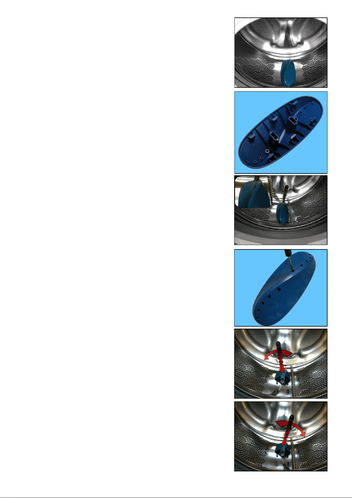
13.3.3 Blade
The blade is secured to the drum with slides and secured with blades
carved into the drum.
The blades are secured in place by six slides (as can be seen in the picture)
which fit into purpose-provided runners in the drum strip.
To release the blade from the drum:
Insert a flat-tip screwdriver into the hole (as shown in the figure)
The hole is the first in the second series towards the rear of the blade
With the screwdriver tilted towards the left
Push the right-hand tab down.
With the screwdriver tilted towards the right
Push the left-hand tab downwards.
Technical Support - MDM 64/84 599 78 10-24 Rev.01
Page 65
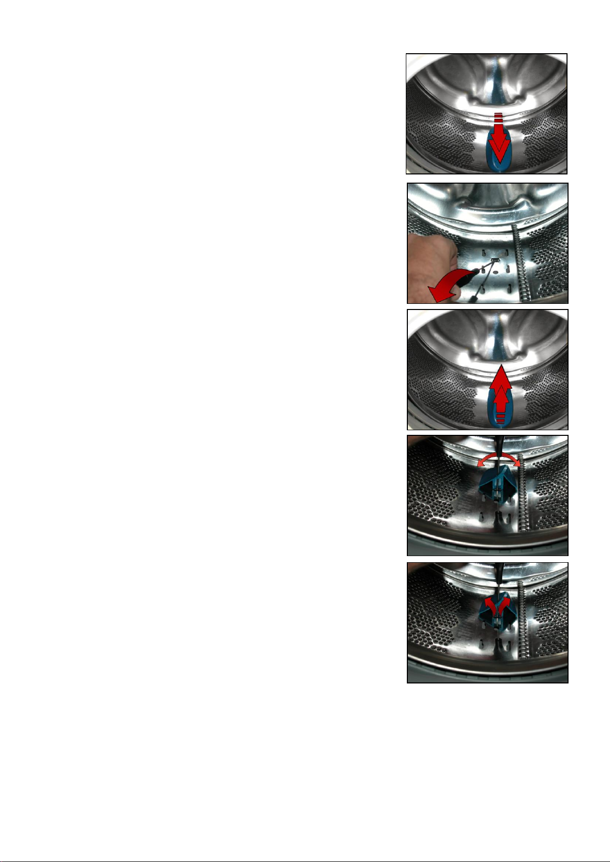
When the two tabs are down
Push the blade towards the front of the drum
Reassembling the blade onto the drum
Before securing the new blade
Insert a flat-tip screwdriver beneath the lock tabs and raise them a little.
Position the new blade inside the drum guides.
Push it towards the back.
Insert the screwdriver (in the fourth slot) at a right angle to the blade, so as
to position it at the centre of the two lock tabs.
Move to the left and right
to move the tabs up (as shown by the arrows) and insert them inside the
blade, securing it to the drum (as shown in the figure).
Technical Support - MDM 65/84 599 78 10-24 Rev.01
Page 66
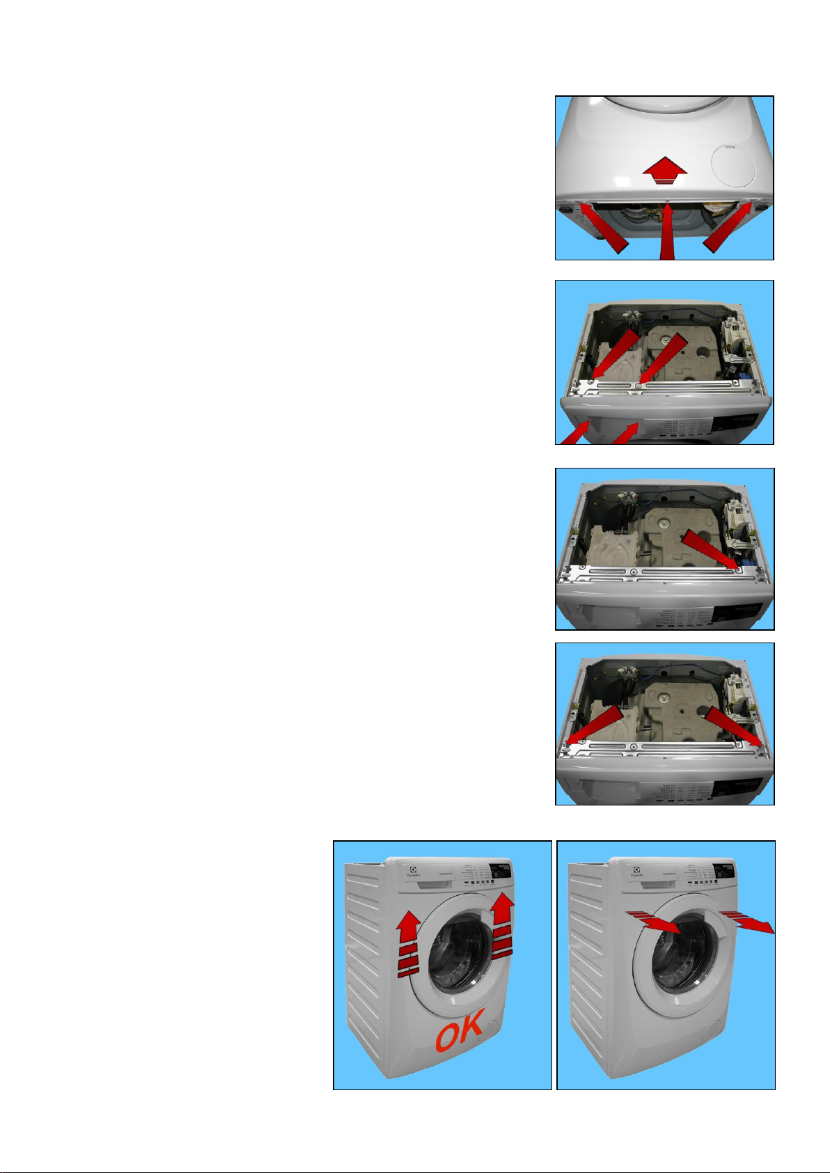
13.3.4 Front panel
Remove the worktop (see relevant paragraph).
Remove the iron ring, remove the door bellow seal from the front panel.
Release the door safety device (see relevant paragraph).
Tilt the washing machine towards the back.
Unfasten the three screws securing the front panel at the bottom.
Raise the lower part a little without removing it entirely
Pull out the detergent dispenser (see relative paragraph)
Remove the two screws securing the detergent dispenser to the control panel
Loosen the screws which secure the dispenser to the crosspiece
Remove the clamp that secures the wiring
Remove the wiring connector connecting the display board.
Remove the four screws which secure the crosspiece to the cabinet.
To remove the front panel, first lift it up and
then pull it out of its supports.
Take care not to warp the screw seats,
because reassembly and front panel/side
panel alignment will be difficult if they are
warped.
Technical Support - MDM 66/84 599 78 10-24 Rev.01
Page 67
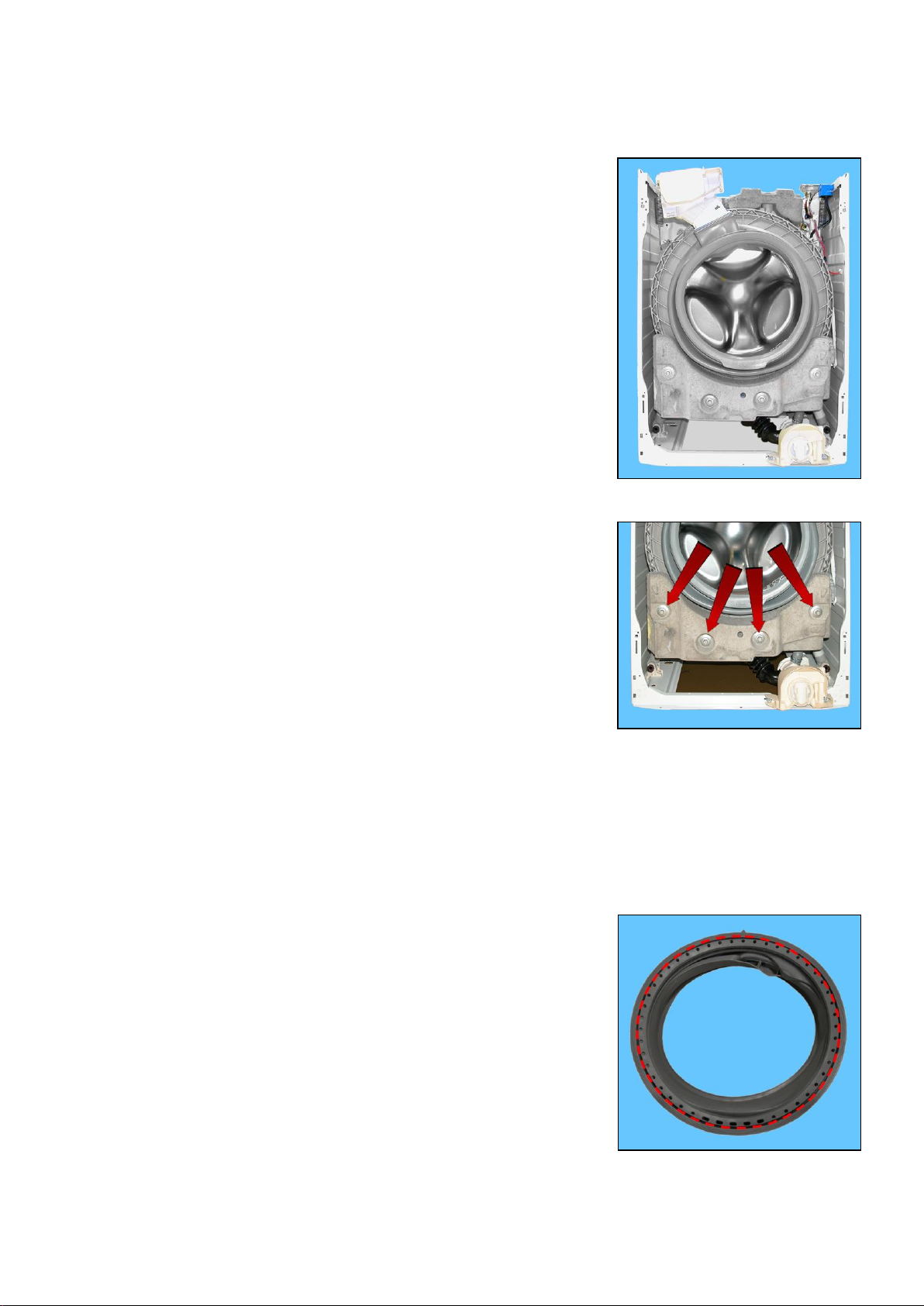
1
2 3 4
5
13.4 From the front panel, you can access
13.4.1 For appliances with drain filter removable from the outside
1. The front counterweight
2. Bellow seal
3. The drain water circuit
4. The welded tub assembly
5. The tub suspension springs
13.4.1.1 Front counterweight
Remove the worktop (see relevant paragraph).
Remove the iron ring securing the bellow seal to the front panel.
Release the door safety device (see relevant paragraph).
Remove the front panel (see relevant paragraph).
Loosen the four screws securing the front counterweight to the welded tub
assembly
The counterweight weighs 10.5 kg.
When reassembling:
tighten the screws at a torque of 20 Nm if the tub assembly is new,
if it isn't new, the tightening torque should be reduced to 15 Nm.
13.4.1.2 Bellow seal
Remove the worktop (see relevant paragraph).
Remove the iron ring securing the bellow seal to the front panel.
Release the door safety device (see relevant paragraph).
Remove the front panel (see relevant paragraph).
Pull out the detergent dispenser from the bellow seal detergent inlet pocket.
Take the seal out of the welded tub.
(take care as the seal is held in position by a snap ring)
When reassembling the seal
Use liquid soap to lubricate the part where the tub is inserted (indicated by the
red circle).
Make sure the references are aligned.
Reassemble the snap ring between the door bellow seal and the tub.
Reassemble the iron ring between the door bellow seal and the cabinet.
Technical Support - MDM 67/84 599 78 10-24 Rev.01
Page 68
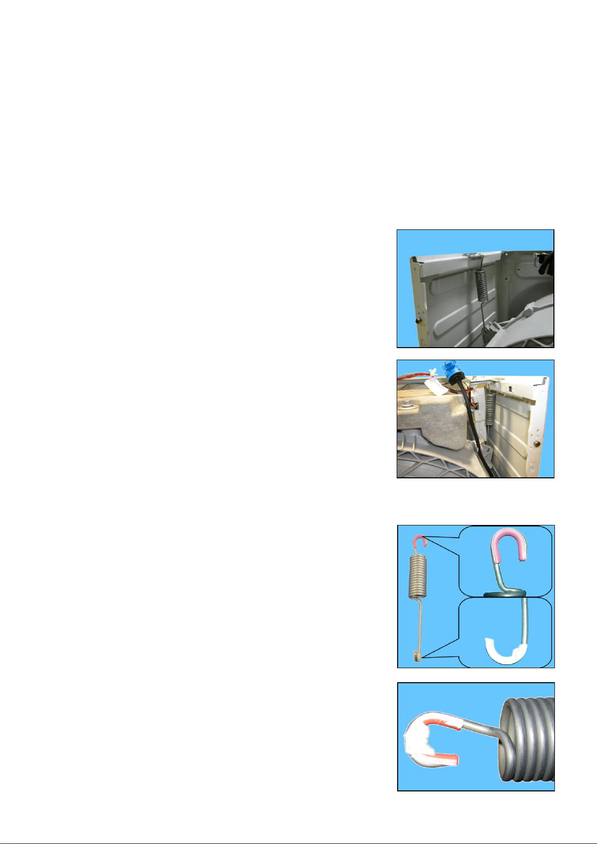
13.4.1.3 Welded tub assembly
Empty the drain circuit
Remove the worktop (see relevant paragraph).
Remove the front panel (see relevant paragraph).
Remove the detergent tray (see relevant paragraph).
Remove the upper counterweight (see relevant paragraph).
Remove the front counterweight (see relevant paragraph).
Remove the back panel (see relevant paragraph).
To remove the washing unit assembly, disconnect:
All the tub pipes, the wiring connectors that connect the heating element, the NTC probe, remove the belt and the
motor (to lighten the tub).
Lay the appliance on its back (making sure you place a polystyrene or cardboard layer on the floor to prevent
damaging the cabinet).
Take the tub out of the washing machine
13.4.1.4 Tub suspension springs
Left spring
Attach the spring as shown in the figure: the shortest leg faces towards the
side, whereas the longest leg faces towards the welded tub.
Right spring
The instructions provided for the left spring also apply to the right spring.
When reattaching the springs (after repair work which required their removal), make sure that the bushings
shown in the figure are featured on both ends (the colour of the bushings in the photos below may vary).
Pay attention to the differences between the bushings (see enlarged details).
Spare bushings are available, under the following codes:
Upper bushing Code 405 50 62-51/9
Lower bushing Code 405 50 62-52/7
Apply some grease on either end of the spring. Use grease
cod. 5318 00 10-97/6
Technical Support - MDM 68/84 599 78 10-24 Rev.01
Page 69
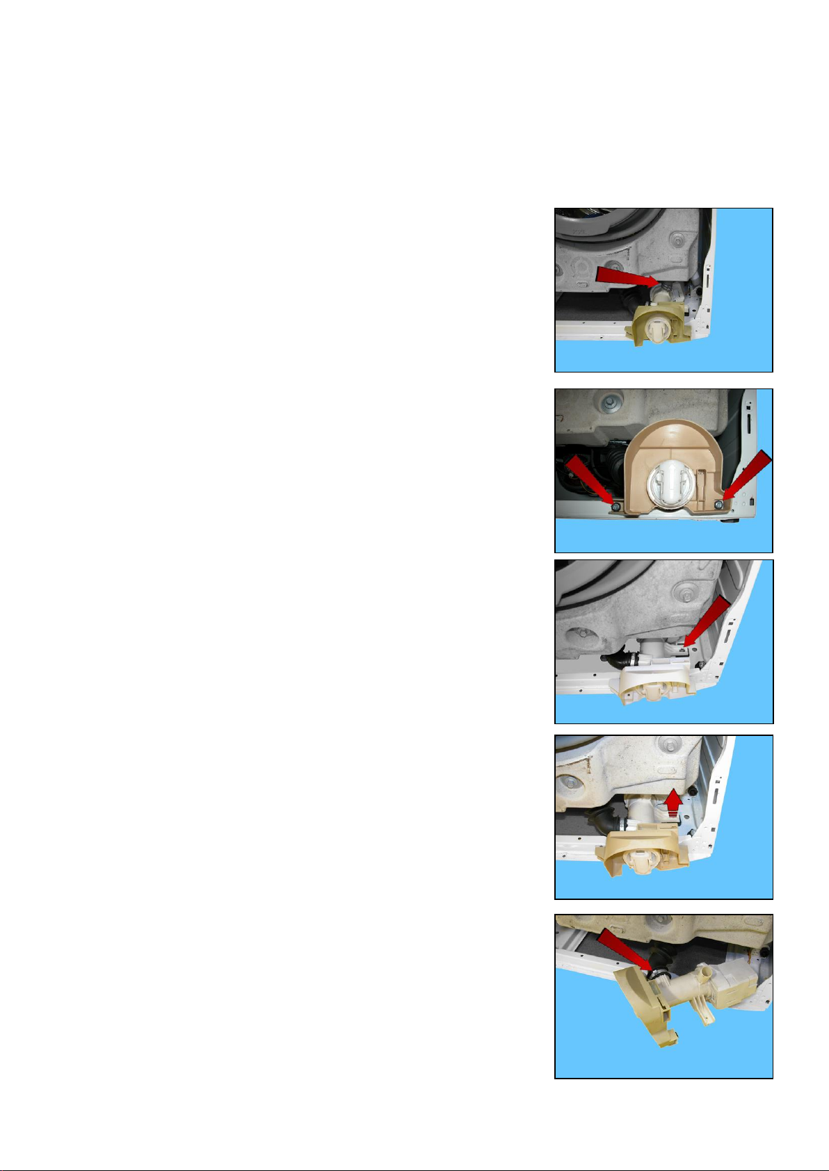
13.4.1.5 Drain water circuit
13.4.1.5.1 Filter body
Remove the worktop (see relevant paragraph).
Remove the iron ring securing the bellow seal to the front panel.
Release the door safety device (see relevant paragraph).
Remove the front panel (see relevant paragraph).
Pull out the main drain pipe
Loosen the screws securing it to the front crossbar.
Loosen the screw fixing the support to the side crosspiece
Lift the filter body to extract the support inserted on the side crossbar.
Break/widen the clamp
When reassembling, make sure the references are positioned correctly.
The size of the clamp to use is 40.5 mm.
Technical Support - MDM 69/84 599 78 10-24 Rev.01
Page 70
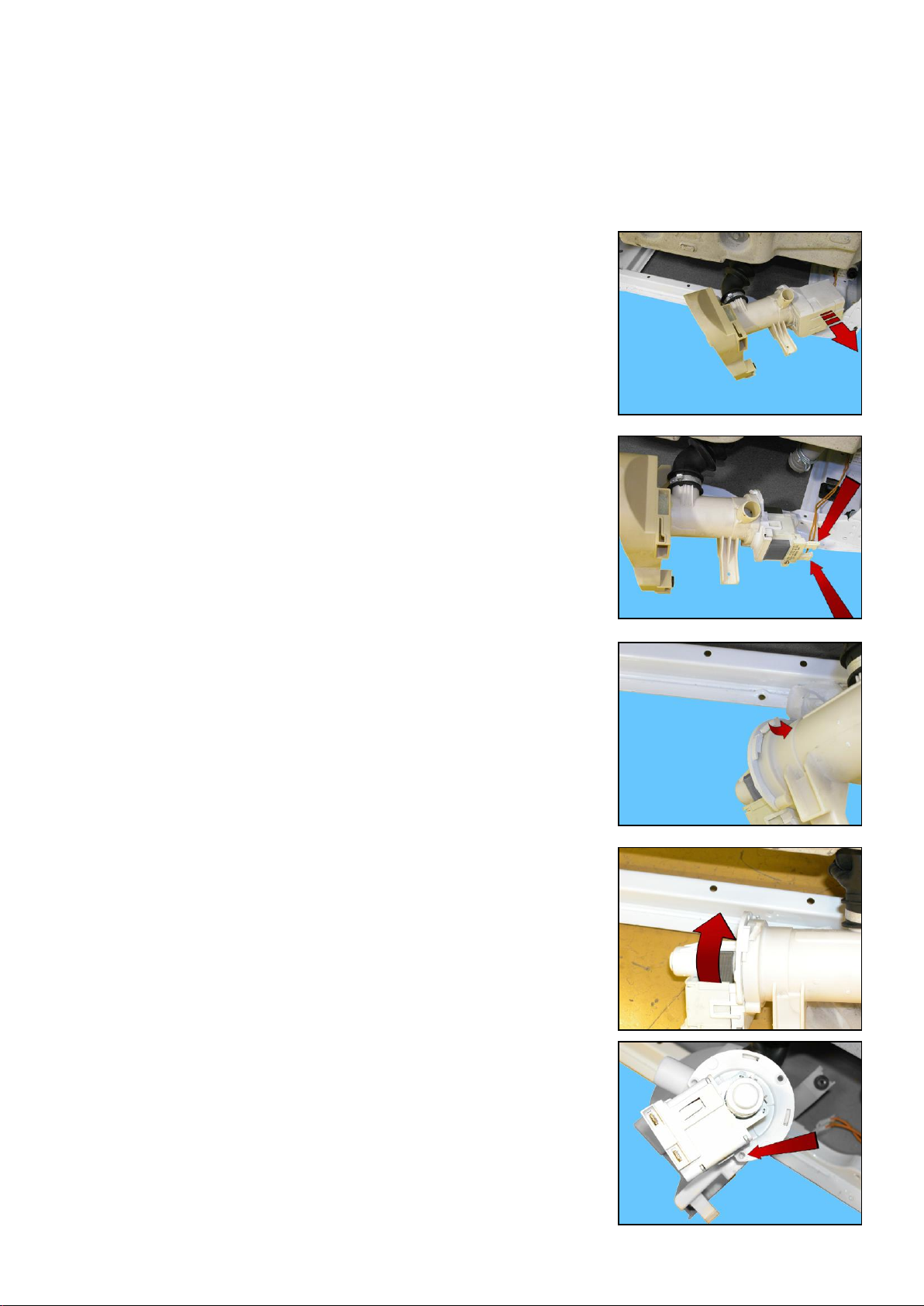
13.4.1.5.2 Drain pump
Remove the worktop (see relevant paragraph).
Remove the iron ring securing the bellow seal to the front panel.
Release the door safety device (see relevant paragraph).
Remove the front panel (see relevant paragraph).
Remove the filter body
Remove the pump protection
Remove the connectors
Using a pair of pliers, raise the anchor tab to release the pump
Turn and pull out the pump
If the lock catch securing the pump to the filter body breaks.
Secure the pump to the filter body, securing it in place using a screw, screwing
the latter in the slot shown by the arrow.
Size of the screw 3.5 x 19 Code 5024 79 51- 00/2
Technical Support - MDM 70/84 599 78 10-24 Rev.01
Page 71
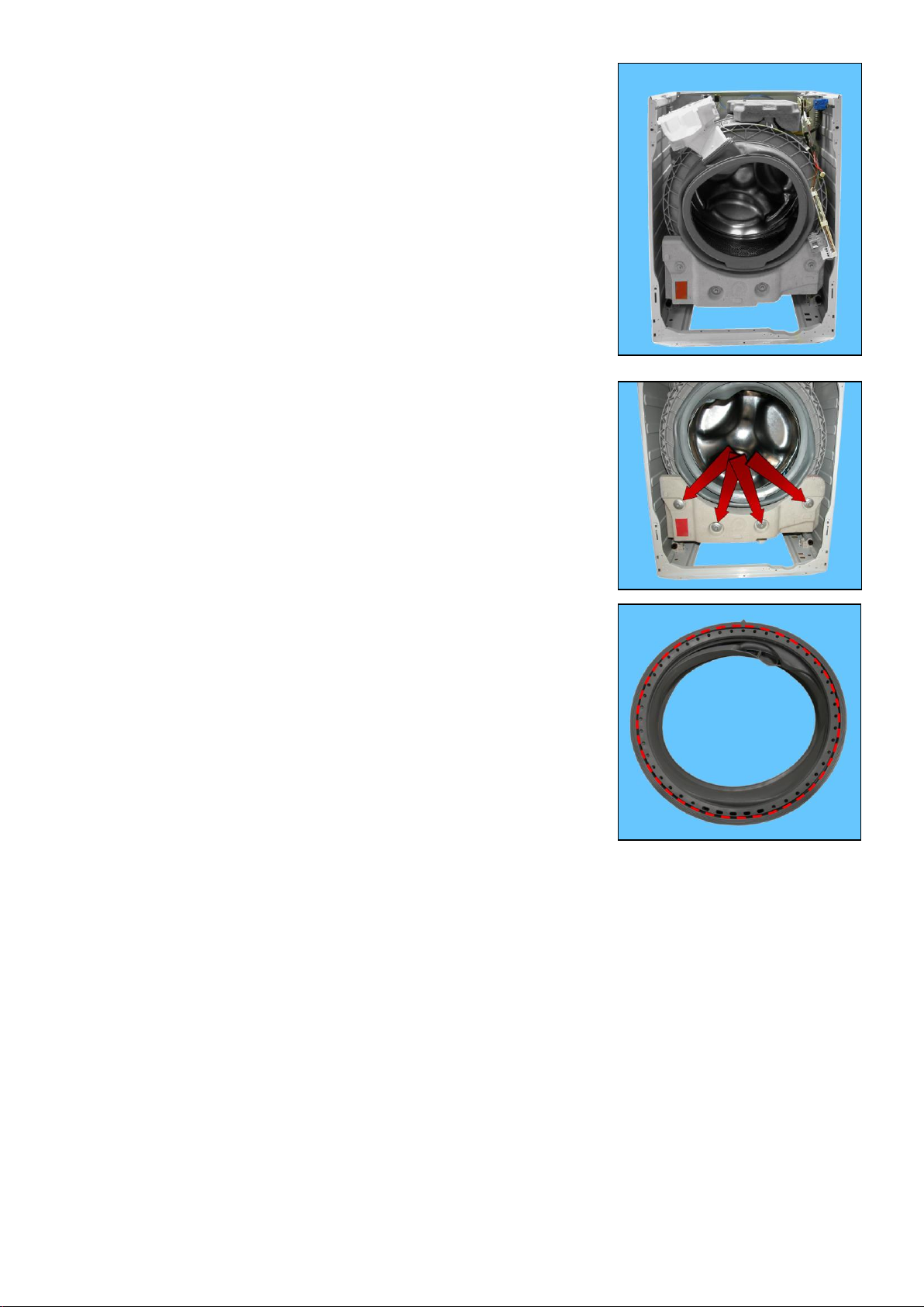
1
2
3
4
13.4.2 For appliances with drain filter not removable from the outside
1. The front counterweight
2. Bellow seal
3. The welded tub assembly
4. The tub suspension springs
13.4.2.1 Front counterweight
See para. 13.4.1.1 page 67
13.4.2.2 Bellow seal
See para. 13.4.1.2 page 67
13.4.2.3 Welded tub assembly
See para. 13.4.1.3 page 68
13.4.3 Tub suspension springs
See para. 13.4.1.4 page 68
Technical Support - MDM 71/84 599 78 10-24 Rev.01
Page 72
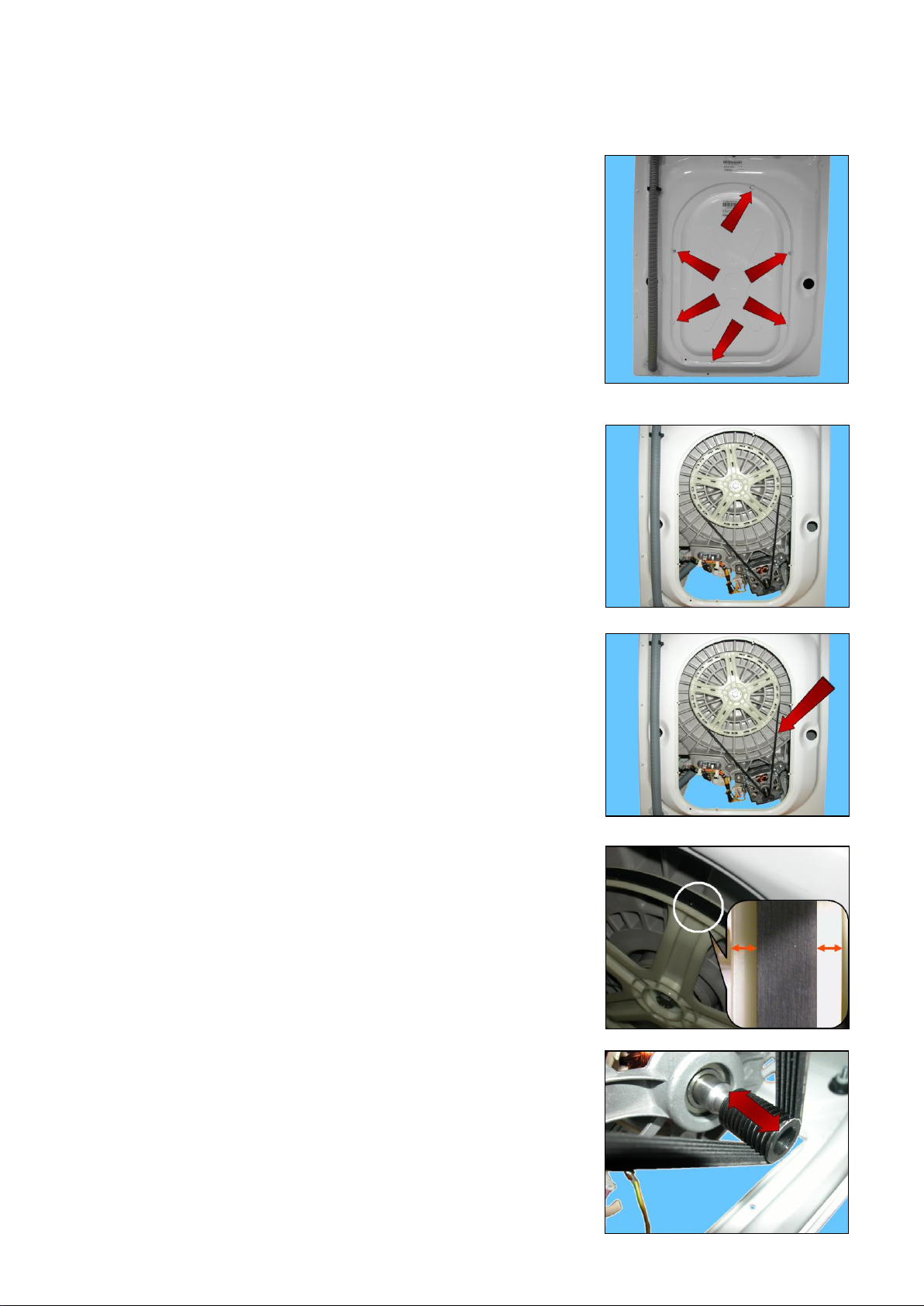
1
2
3
1
2
13.5 Accessing the rear part
Make sure you wear gloves, because parts of the cabinet are sharp
13.5.1 Back panel
Loosen the screw by a few turns (1)
Loosen the screws that secure the sides of the back panel to the cabinet.
Loosen the screw (2) that secures the back panel to the cabinet.
13.6 From the back panel, you can access
1. Belt
2. Plastic pulley ( 273 mm)
3. Motor
4. Heating
13.6.1 Belt
Remove the back panel (see relevant chapter).
Hold the belt, and by turning the pulley, remove it.
When reassembling:
Position the belt and align it with the centre of the pulley ( 273 mm) as shown
in the figure.
Turning the pulley, check that the belt positions itself and remains in the
central part of the pulley.
If necessary, adjust the position of the belt on the drive pulley, so that it is
correctly positioned.
Technical Support - MDM 72/84 599 78 10-24 Rev.01
Page 73
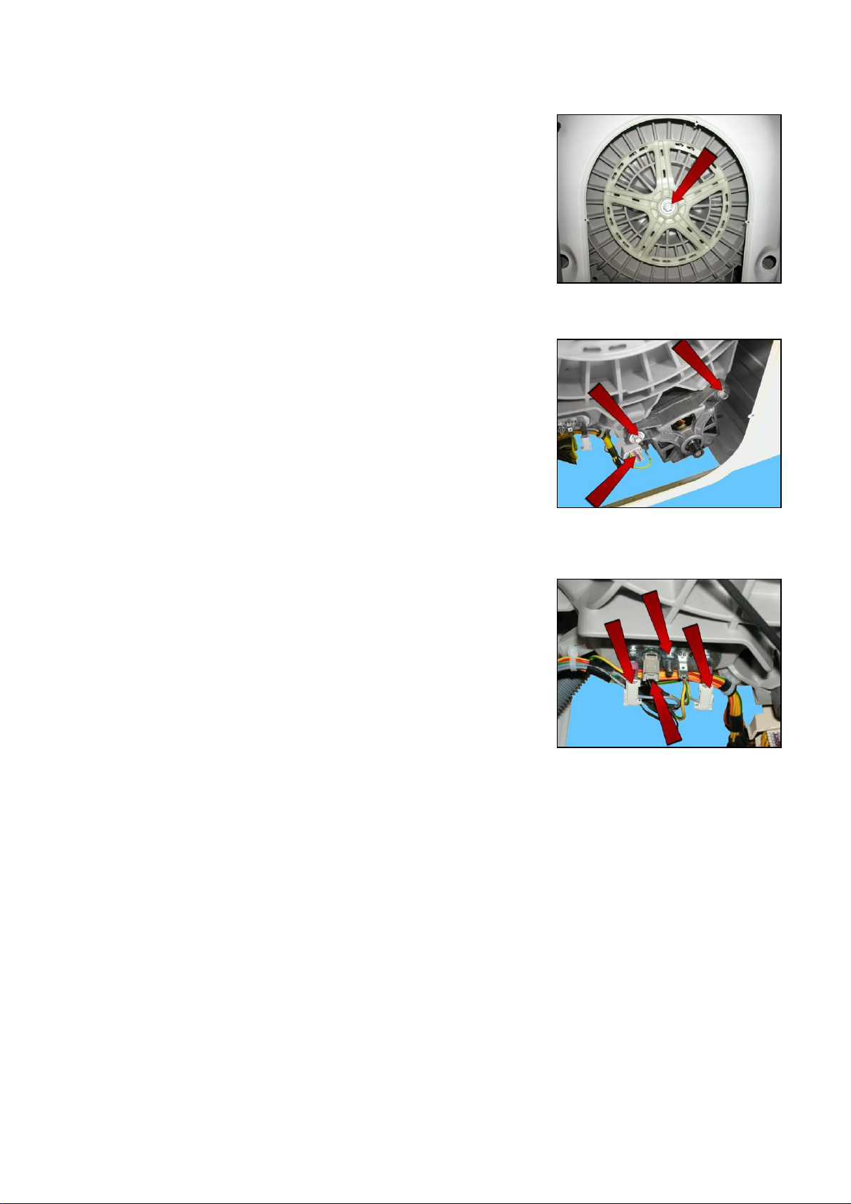
1 2 2
1 1 2
3
13.6.2 Plastic pulley ( 273 mm)
Remove the back panel (see relevant chapter).
Remove the belt (see relevant chapter).
Insert a retainer to secure the pulley in place.
Unfasten the screw securing the pulley to the drum shaft.
When reassembling, tighten the screw at a torque of 60 Nm.
13.6.3 Motor
Remove the back panel (see relevant chapter).
Remove the belt (see relevant chapter).
Disconnect the power supply connector (1) and the earth faston (beware as it
is fitted with an anti-sliding stop).
Loosen the two front fastening screws (2) as there are no rear ones.
When reassembling:
Restore the connections.
If the clamp securing the wiring to the motor breaks, replace it with a new one.
When reassembling, tighten the screws at a torque of 11.5 Nm.
13.6.4 Heating
Remove the back panel (see relevant chapter).
Disconnect the connectors of the heating element (1) and NTC probe (2).
Loosen the nut (3) and pull it out.
When reassembling, tighten the nut at a torque of 4 Nm.
Technical Support - MDM 73/84 599 78 10-24 Rev.01
Page 74
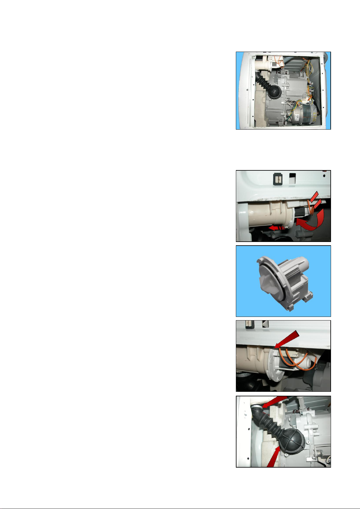
1 2 3
3
13.7 From the base of the appliance, you can access
13.7.1 For appliances with drain filter removable from the outside
1. Drain water circuit
2. Pressure chamber
3. Shock absorbers
13.7.1.1 Drain water circuit
13.7.1.1.1 Drainage pump
Remove the back panel to make certain operations easier.
Empty the drain circuit
Lay the appliance onto its left side (the side where the detergent dispenser is)
Using a pair of pliers, raise the anchor tab to release the pump
At the same time
Turn the pump and pull it out of the filter body
Remove the protection and disconnect the connectors
Pump
If the lock catch securing the pump to the filter body breaks.
Secure the pump to the filter body, securing it in place using a screw, screwing
the latter in the slot shown by the arrow.
Size of the screw 3.5 x 19 Code 5024 79 51- 00/2
13.7.1.1.2 Tub drain pipe
Empty the drain circuit
Lay the appliance onto its left side (the side where the detergent
dispenser is)
Loosen the screw that tightens the clamp (on the tub side)
Widen/break the clamp (on the filter body side)
When reassembling, replace the clamp with one with identical characteristics and with a diameter of 40.5 mm
Technical Support - MDM 74/84 599 78 10-24 Rev.01
Page 75
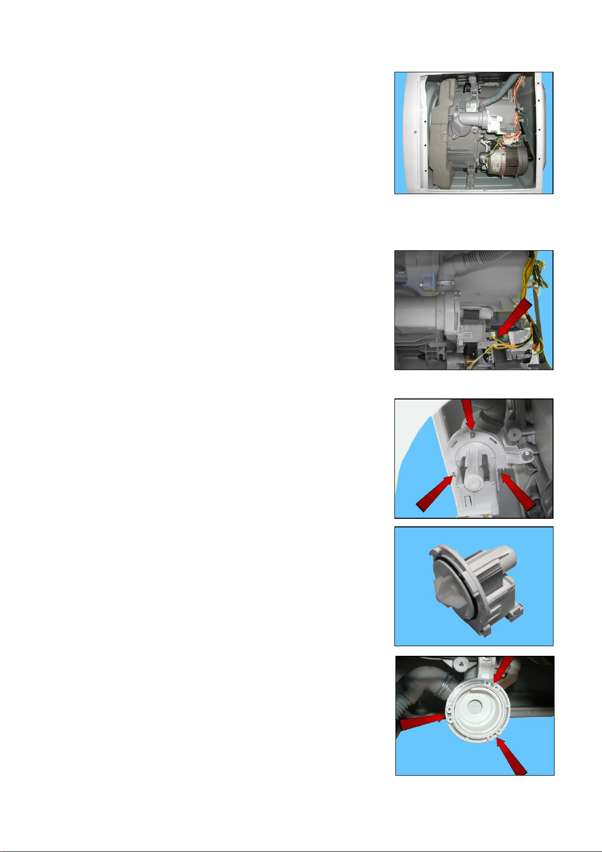
1 2 3
3
13.7.2 For appliances with drain filter not removable from the outside
1. Drain water circuit
2. Pressure chamber
3. Shock absorbers
13.7.2.1 Drain water circuit
13.7.2.1.1 Drainage pump
Remove the back panel to make certain operations easier.
Empty the drain circuit
Lay the appliance onto its left side (the side where the detergent dispenser is)
Disconnect the connectors.
Before removing the pump, make sure the drain circuit is empty.
Place a protection over the motor to avoid any water drops from falling into it
Loosen the three screws which secure it to the new drain circuit
(IDB see page 76)
When reassembling:
tighten the screws at a torque of 1.5 Nm.
Pump
Once you have removed the pump, you will see that the IDB features six slots,
if three of the slots are damaged, you can use the other three.
Technical Support - MDM 75/84 599 78 10-24 Rev.01
Page 76
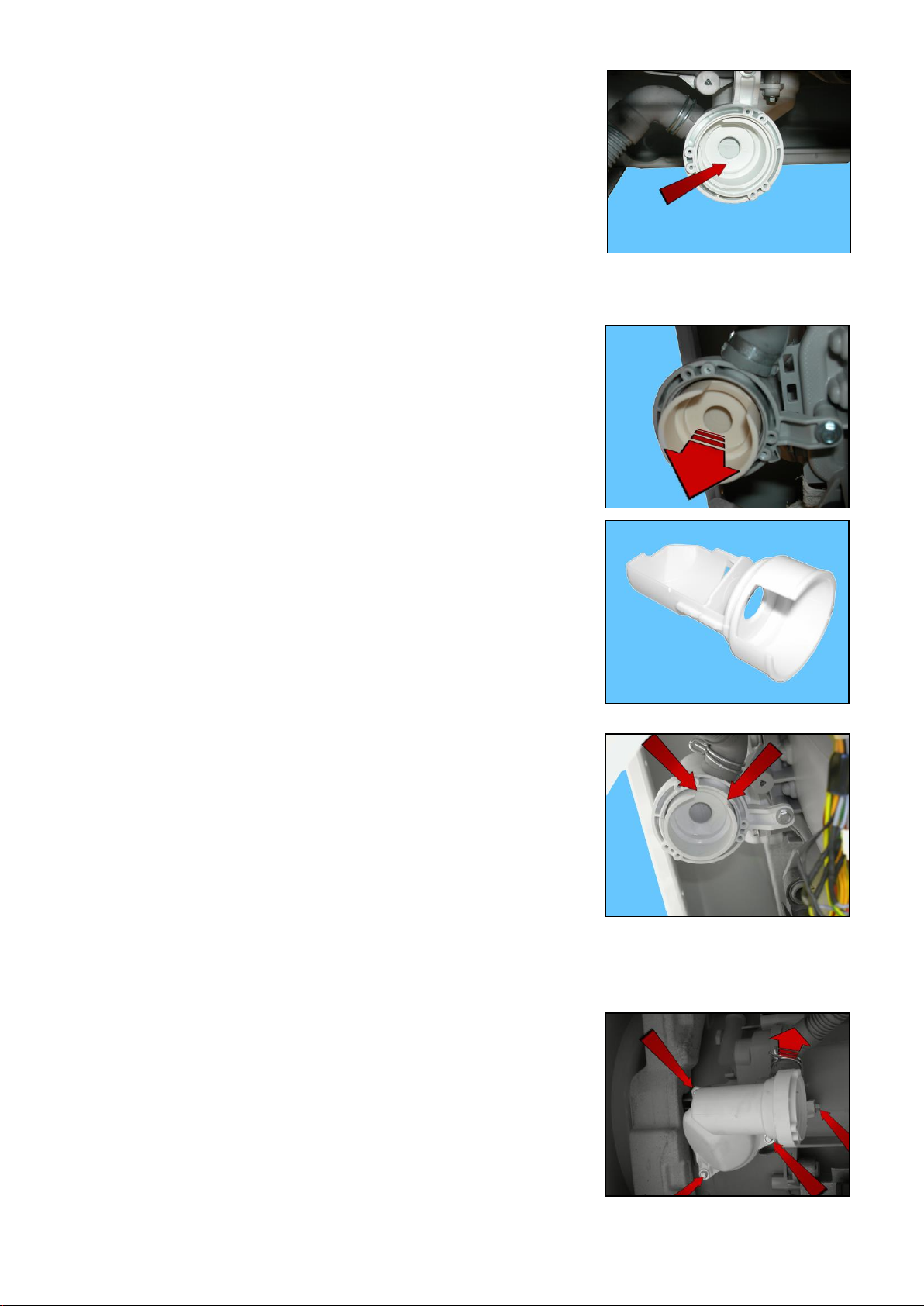
And the fluff filter is in the centre of the IDB
When reassembling, repeat the same steps in the reverse order, tightening
the screws at a torque of 1.5 Nm.
13.7.2.1.2 Drain filter
Remove the back panel to make certain operations easier.
Empty the drain circuit
Lay the appliance onto its left side (the side where the detergent dispenser is)
Remove the pump (see relevant paragraph)
Take the filter out of its seat (IDB)
Filter or needle trap
When inserting the filter in its seat, make sure the indented part (shown by the
arrows) is facing towards the drain pipe.
If inserted incorrectly, it will be difficult to insert the filter completely in its seat
If the filter has not been inserted or if it has been positioned incorrectly, the
appliance will report the alarm E21.
13.7.2.1.3 IDB (Integrated Drain Body)
Remove the drain pump (see relevant paragraph)
Pull out the main drain pipe
Remove the screws that secure it to the welded tub
Technical Support - MDM 76/84 599 78 10-24 Rev.01
Page 77
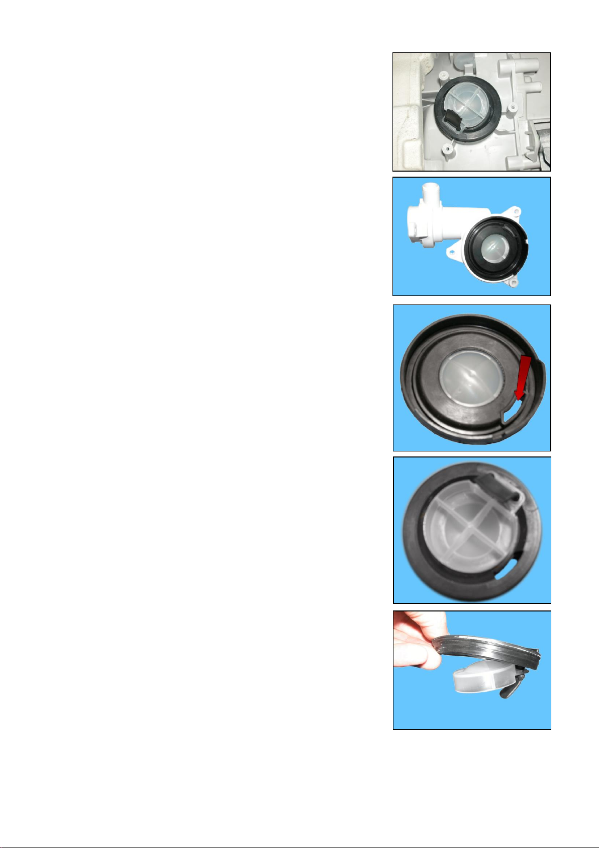
Once you have removed the outside of the IDB
Attached to the welded tub, the diaphragm assembly with the floating valve
remains
Remove the diaphragm assembly
IDB complete with diaphragm assembly
Diaphragm assembly seen from the welded tub part
The side window - referred to as the “vent” (shown by the arrow) allows you to
keep the drain circuit balanced to achieve good performance.
Diaphragm assembly seen from the IDB side
Technical Support - MDM 77/84 599 78 10-24 Rev.01
Page 78
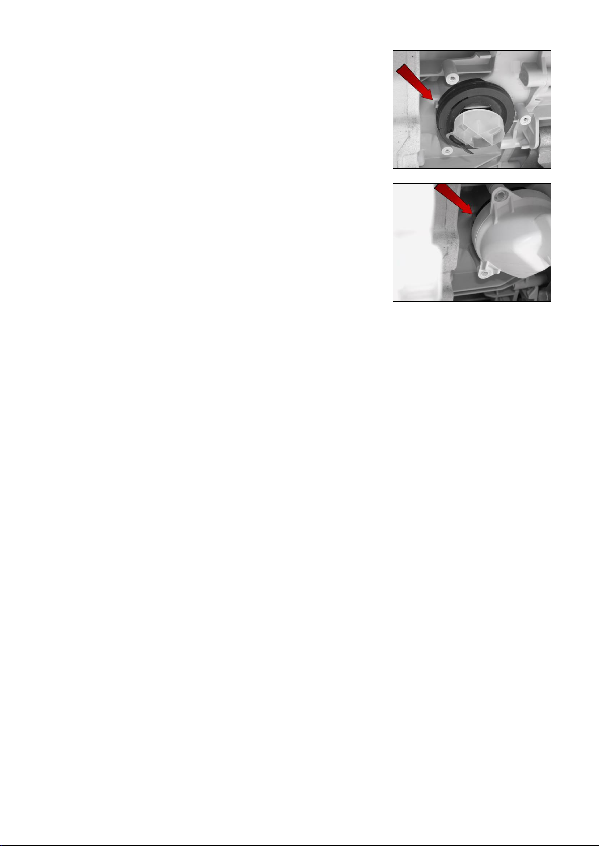
When reassembling
Place the diaphragm assembly and floating valve in the drain hole of the
welded tub
Make sure the reference mark is positioned correctly in the seal diaphragm
assembly seat
When positioning the IDB lid, make sure it fits as far as it can go against the
reference point.
When reassembling
Repeat the same steps in the reverse order, tightening the screws at a torque of 5 Nm.
Technical Support - MDM 78/84 599 78 10-24 Rev.01
Page 79
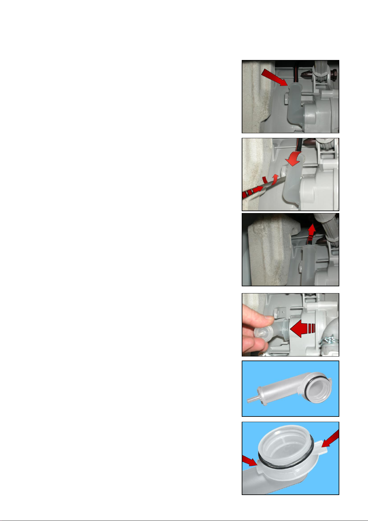
13.7.3 Pressure chamber (both versions)
Empty the drain circuit
Lay the appliance onto its left side (the side where the detergent dispenser is)
Insert a flat-tip screwdriver between the pressure chamber and the hook
securing it to the welded tub.
Turn it anti-clockwise while at the same time removing the chamber.
Take care not to damage it
Remove the pipe connecting to the analogue pressure switch
Turn it until you reach the position shown in the figure.
Remove it.
Pressure chamber
Detail of the pressure chamber set into the welded tub
When reassembling
Make sure that the seal is not damaged/warped, otherwise replace it.
Technical Support - MDM 79/84 599 78 10-24 Rev.01
Page 80
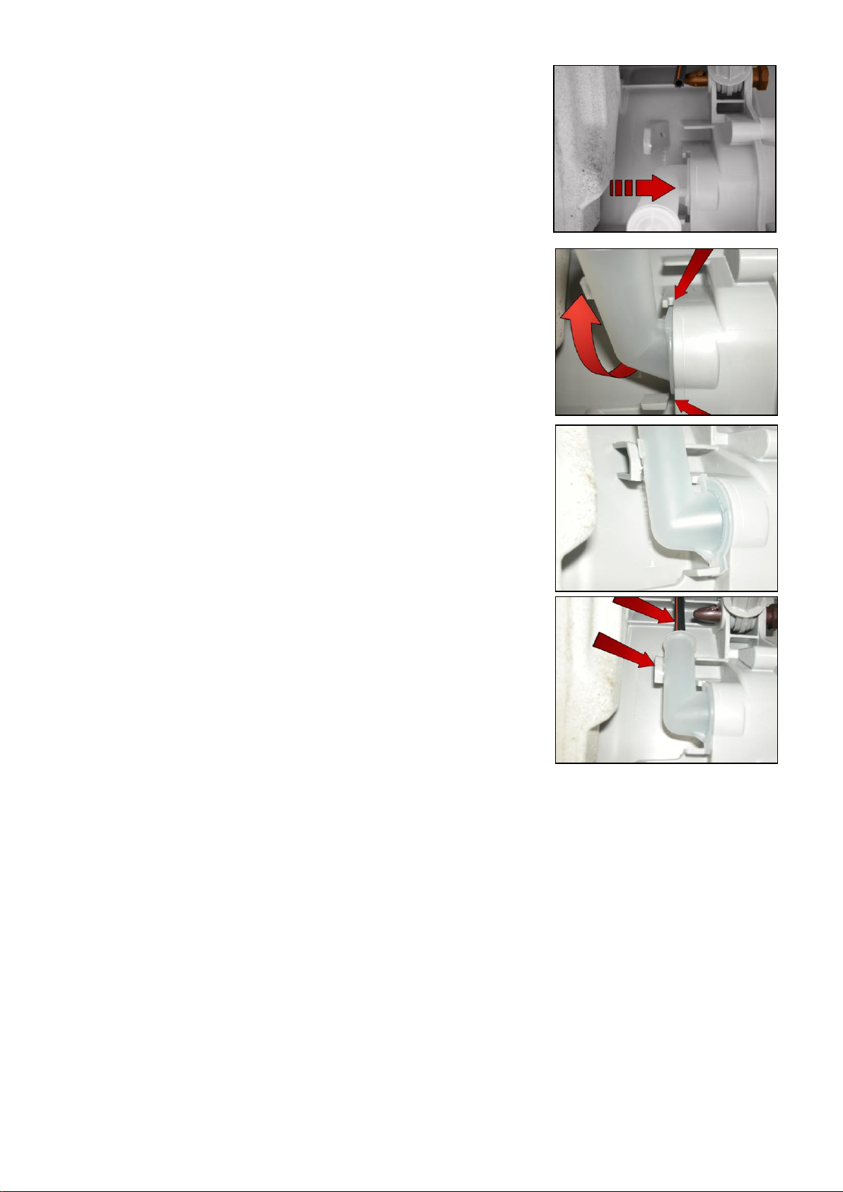
Insert the pressure chamber in its seat in the welded tub.
Turn it and make sure that the two tabs slot into the purpose-provided runners
(shown by the arrows)
As shown in this picture
Insert the pipe and secure the pressure chamber
Technical Support - MDM 80/84 599 78 10-24 Rev.01
Page 81
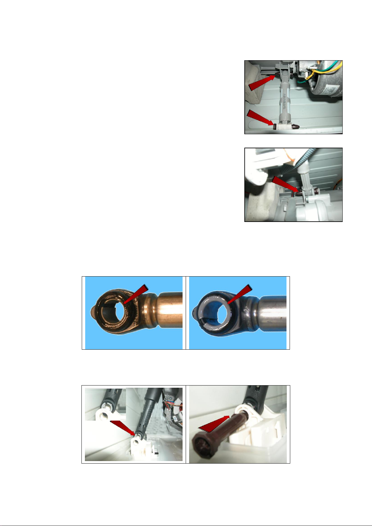
Narrow edge
Wide edge
13.7.4 Shock absorbers (both versions)
Empty the drain circuit
Lay the appliance onto its left side (the side where the detergent dispenser is)
Right-hand shock absorber from the rear
Pull out the pins securing it to the tub and to the side crosspiece
Left-hand shock absorber from the rear
Pull out the pins securing it to the tub and to the side crosspiece
13.7.5 Shock absorber pin (both versions)
The principle is still the same, even if the photographs show different components and situations.
There is a bushing on either end of the shock absorber. It has a wider profile on one end to avoid it becoming
dislodged when the pin is inserted (see the two figures below).
When positioning the shock absorber inside the fastening (situated at the bottom of the cabinet or in the tub), take
care when positioning the bushing, so as to insert the pin from the part of the bushing with the widest profile.
The spare bushing is supplied under Code 344 91 25-30/5
If you are having difficulty inserting the pin, grease it a little (code 5026 24 16-00/6).
Technical Support - MDM 81/84 599 78 10-24 Rev.01
Page 82
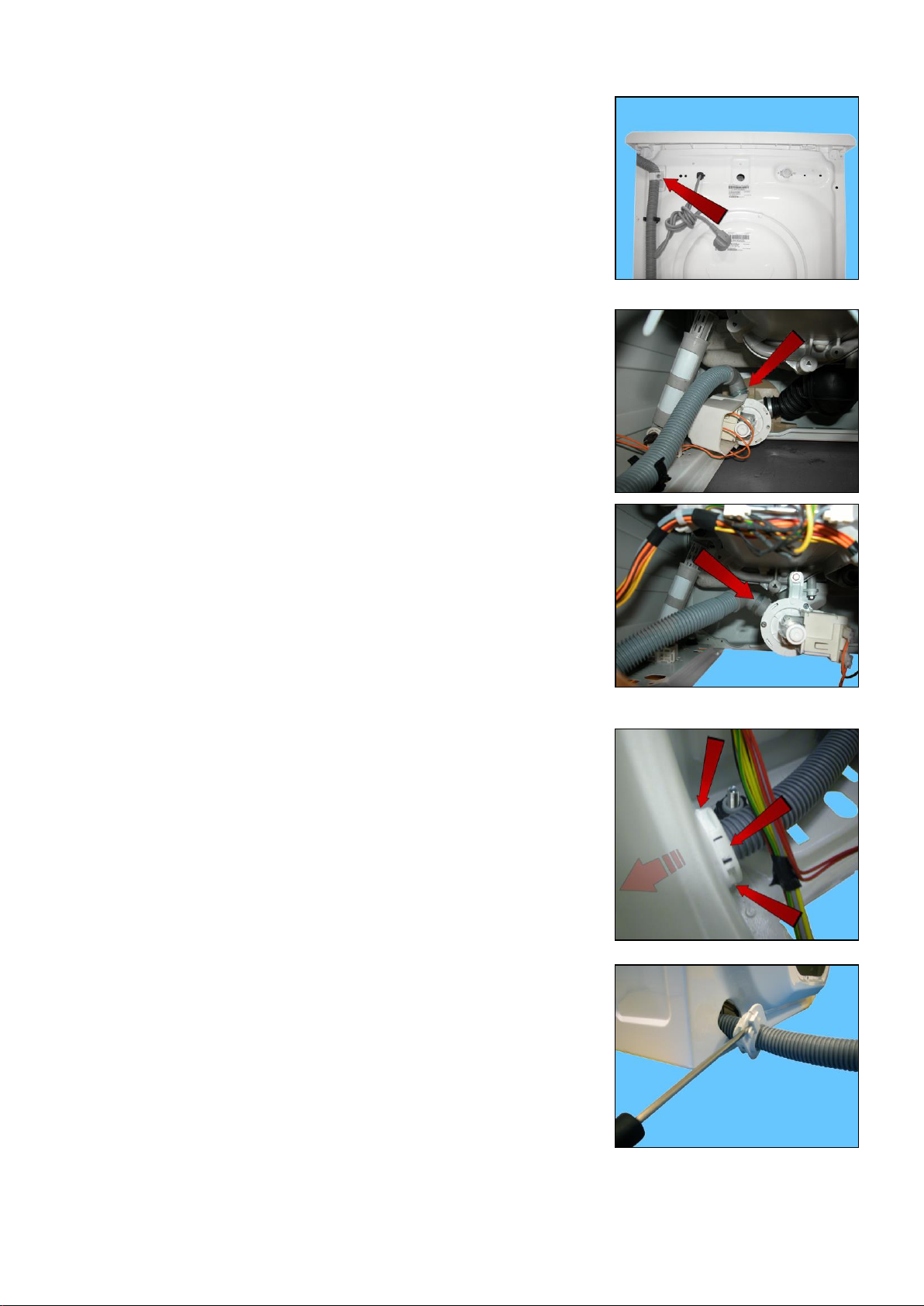
13.7.6 Main drain pipe
Loosen the screw which fastens the pipe fastener at the top of the appliance
Straighten out the pipe to drain the water into a container.
Remove the back panel (see relevant chapter).
Appliances with drain filter removable from the outside
Open/warp the clamp (shown by the arrow) which secures the drain pipe to the
pump body assembly.
Appliances with drain filter not removable from the outside
Open/warp the clamp (shown by the arrow) which secures the drain pipe to the
IDB.
If the clamp breaks, replace it with one featuring the same characteristics
Remove the pipe fastener that secures it to the cabinet by pressing the three
hooks (indicated by the arrows) and pull it out at the same time.
Insert a screwdriver to open up the cabinet pipe fastener.
Technical Support - MDM 82/84 599 78 10-24 Rev.01
Page 83
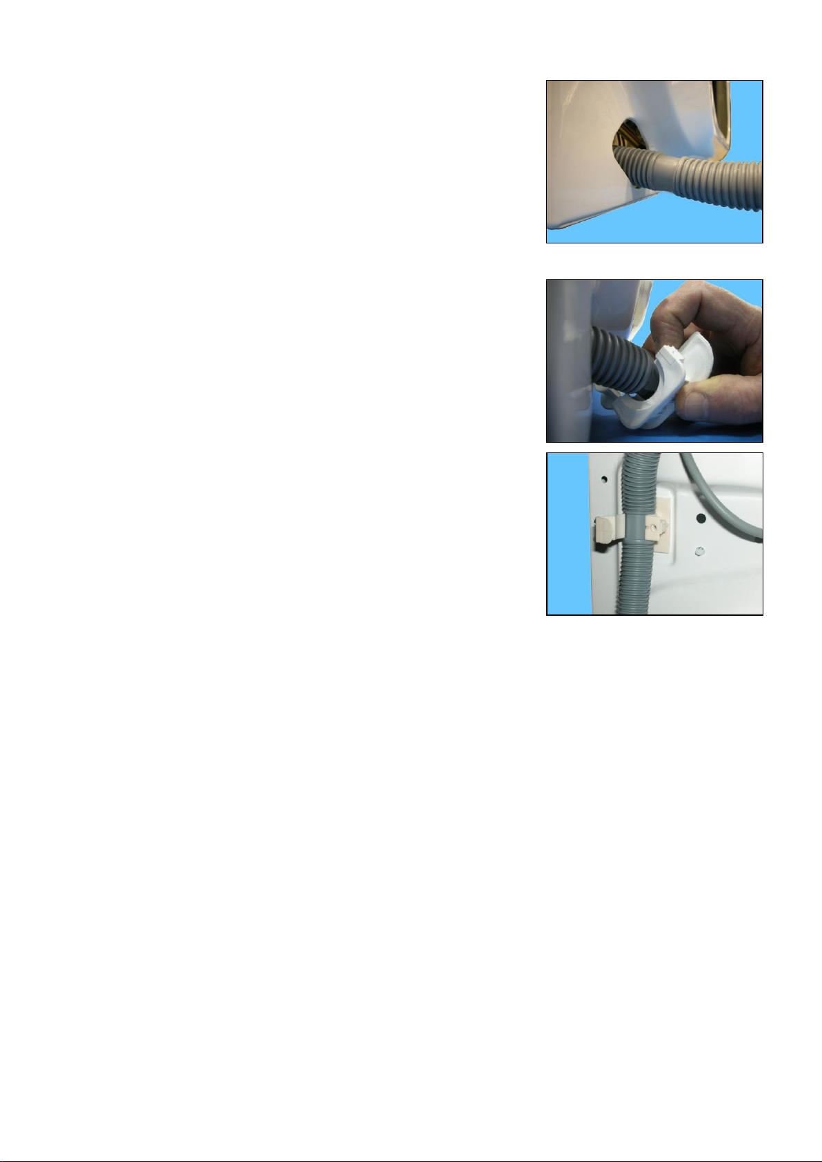
When refitting the pipe, make sure that the non-corrugated part
is inserted in the seat of the pipe fastener.
The other uncorrugated part of the pipe must be positioned in the pipe fastener
at the top of the appliance.
When reassembling, repeat all these steps in the reverse order.
Technical Support - MDM 83/84 599 78 10-24 Rev.01
Page 84

Revision
Date
Description
Written by
Approved by:
00
09/2014
Document creation
DMM
XX – 0X/201X
01
12/2014
Changed the cover picture
MP
XX – 0X/201X
REVISION:
 Loading...