

Page 1

302 D
Cooker Hood
Installation and Operating Instructions
Page 2
Contents
Page 3
View of the Hood
1) Extendable Vapour Guide
2) Filter Grille
3) Lighting
4) Motor Switch
5) Light Switch
/3^ I i!^°|
41^ 0 I M N1
5 —r-
° ' o
I I Iaeo
Page 4
Page 5
Is..со to
л 1- со со
II II II
л о (О о>
ю
Page 6
^ 529 _
m
1 m
Ю
CO
00_
CO
f-4-
4-
SI
509,5
-4
- 1
Page 7

Page 8

General
The cooker hood can be used :
either as an exhaust air appliance (extraction mode)
or as a return air appliance (recirculation mode)
via a carbon filter (optional extra).
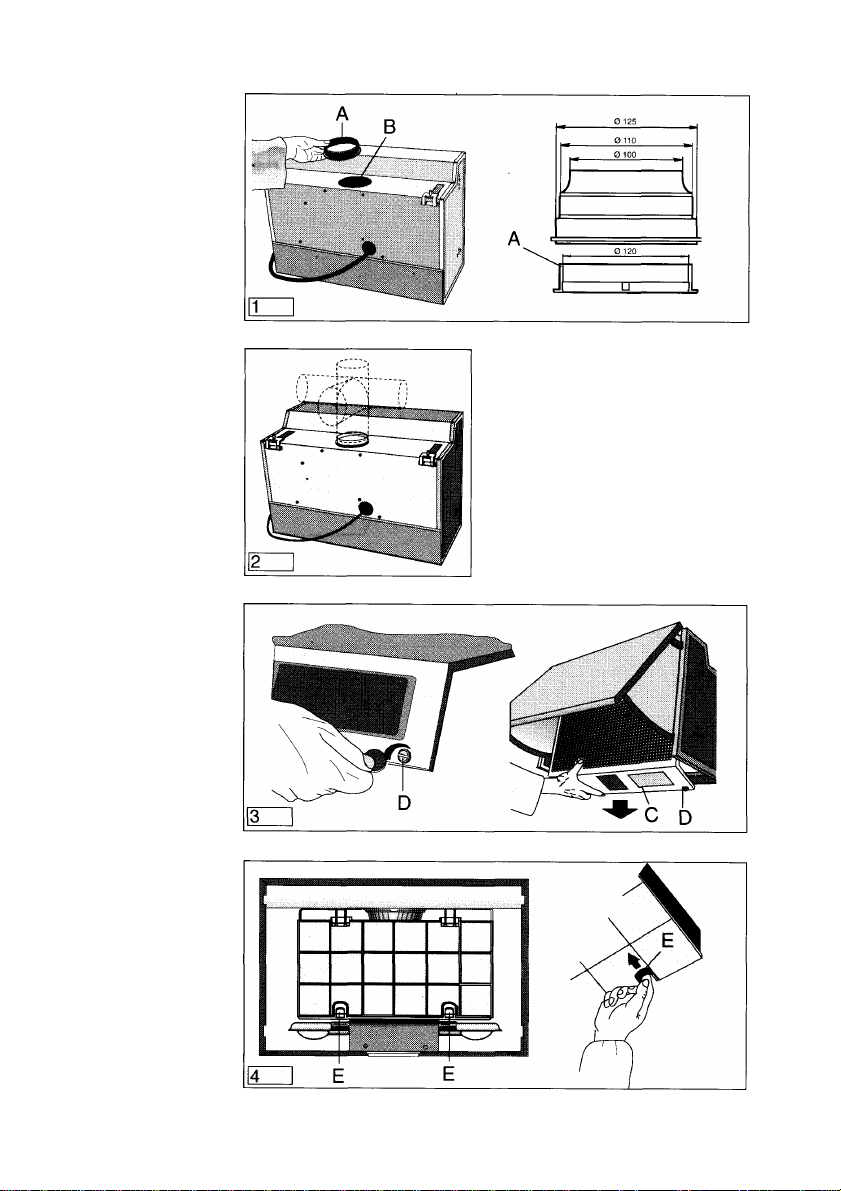
Preparation for installation
Extraction In this mode the fumes are extracted to the outside via a venting
mode hose connected to the coupling ring A, placed in hole B (fig. 1).
Depending on your installation the hose can be directed either
towards the ceiling or towards the walls(fig. 2).
In the extraction mode the outlet venting hose should to be
120mm in diameter, but 100mm or 110mm venting hoses can be
used by inserting the multiconnector flange (fig. 1), supplied with
the hood on the coupling ring A, before connecting the hood to the
outlet venting hose.
If the venting hose runs horizontal it must be slightly slanted
upwards (about 10°) to ensure the air is vented easily from the
kitchen to the outside.
If the hood is to vent out into the open air through an
external wall, you need a telescopic wall box (optional
extra). Wall box and venting hoses are available via your
AEG Stockist or AEG Spare Parts. Flame retardant venting
hose is available in 120 and 100mm diameter. Other flame
retardant materials such as KA piping can be used.
Optimum operation of the cooker hood in the extraction mode is
assured only if the following points afe observed:
- short, straight exhaust air runs
- as few hose bends as possible
- running of the hose in smooth flat arcs not at sharp angles.
- as large as possible hose diameter
Failure to observe these principles will result in serious power
losses and increased operating noise.
Page 9

In this mode the fumes filter through an active carbon filter
(optional extra) and are returned into the room. ^
To fit the carbon filter remove the grille C by turning locks D and
pull it out downwards (fig. 3). Fit the filter in the seat at the front and
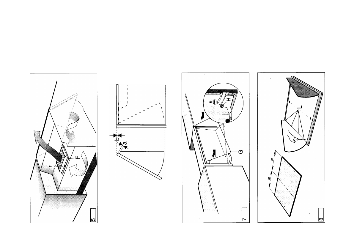
fasten it at the back with the two hooks E (fig. 4). The cover F (fig.
5) must be fitted over the hole B (fig. 1) fixing it with the special
screw provided. This cover deflects the air forwards avoiding
soilage of the rear wall.
Recirculation
mode
Important:
In the extraction mode the exhaust air must not be introduced into
a smoke flue or exhaust gas chimney.Introduction of the exhaust
air into a shaft used for ventilation of the installation spaces of
firerooms is not permitted.
If the exhaust air is introduced into a operational smoke flue or
exhaust gas chimney, it is advisable to seek the advice of a
competent chimney-sweep. The official exhaust air guidance
regulations are to be complied with.
During operation in the extraction mode, an adequate air opening
of approximately the same size as the exhaust air opening should
be ensured.
According to the Provincial Building Regulations, the joint operation
of fume extractor hoods and chimney-linked fireplaces, such as
coal or oil-fired ovens and gas heaters, in the same space is
subject to specific restrictions. In such spaces, the Fireplace
Regulations only allow an underpressure of max. 0.04 mbar. The
safe joint operation of chimney-linked appliances and fume
extractor hoods is only guaranteed if space and/or dwelling
(space/air interaction) are externally vented by a suitable supply
air opening of around 500-600cm2 and an underpressure thereby
avoided when the cooker hood is running. In doubtful cases,
please seek the advice and consent of a competent chimney
sweep or the local building authorities.
Notes prior to
installation
In spaces without a fireplace, the rule is: “Supply an air opening
as large as the exhaust air opening”, the efficiency of the hood in
the extraction mode may be impaired by a greater opening.
Operation of the hood in the recirculation mode in such
circumstances is safe and is not subject to the regulations above.
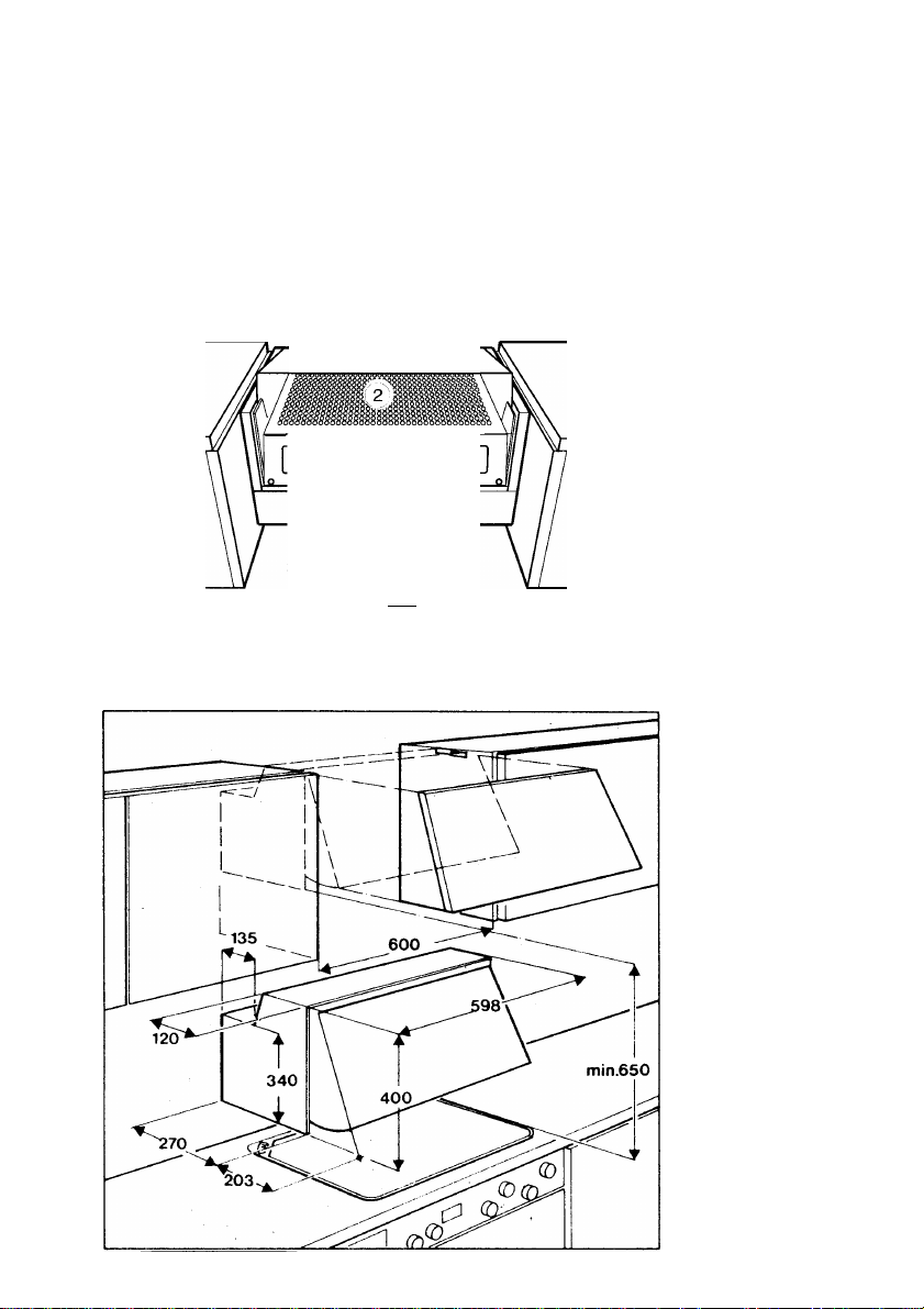
When installed, the minimum distance from the hob to the
lower edge of the cooker hood must be 65cm for electric hobs
or 75cm in the case of gas or mixed fuel hobs
Page 10

Electrical connections
Voltage and
current
Important
# Please ensure that the voltage and current indicated on the rating
plate agree with the voltage of your electricity supply.
If your appliance has been equipped with a mains lead with a
moulded-on type plug, you must comply with the following
regulations:
The plug moulded on to the lead incorporates a fuse. For
replacement, use a 5 amp BS1362 fuse. Only ASTA approved or
certified fuses should be used. If the fuse cover/carrier is lost, a
replacement cover/carried must be obtained from an electrical
goods retailer. If the socket outlets in your home are not suitable
for the plug fitted to the appliance, then the plug must be cut off and
destroyed for safety reasons, and an appropriate plug fitted.
When wiring the plug ensure that all strands of wire aré securely
retained in each terminal. Do not forget to tighten the mains lead
clamp on the plug.
This appliance complies with the following directives:
— 89/336/EEC of 03.05.1989 (including amendments 92/31/
EEC of 28.04.1992 and 93/68/EEC of 22.07.1993),
EMC directive.
Electrical connections
230 V - using fixed power supply line with plug.
240 V - using fixed power supply line (Great Britain).
Fuse rating 13 amps
(The unit should only be connected up by an authorized electrician).
See rating plate for further information.
It is recommended that the socket for the plug is sited above the
cooker hood or above the overhead cabinet.
This has 2 advantages:
1 ) The socket is not visible.
2) The appliance can easily be unplugged when necessary.
If a fixed connection is required the cooker hood should be
connected by an electrical installer registered with a competent
electricity company. An isolating device is to be provided on the
fixed wiring side. Switches with a contact opening of more than
3mm apply as isolating devices.
These include-automatic cut-out switches, fuses and contactors
(VDE0730, s. 7, Parti).
10
Page 11
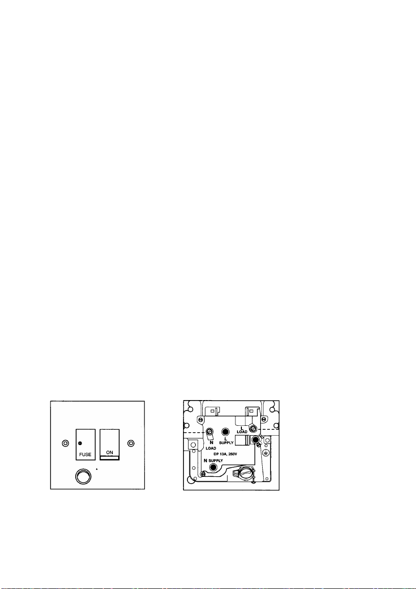
Your appliance must be connected to fixed wiring via the use of
a double pole swiched fused spur outlet with or without pilot lamp.
We strongly recommend the appliance is connected by a quali
fied electrician who is a member of the NICEIC who will comply
with the lEE and any local regulations.
NOTE:
The terminology “DOUBLE POLE” means that both the live
and neutral supplies are swiched and disconnected at the
same time.
The terminations labelled SUPPLY are for the connection for the
internal house wiring and the terminations labelled LOAD are for
the appliance.
IMPORTANT
The wires of the mains lead supplied with this appliance are
coloured in accordance with the following code:
Blue-Neutrai
Brown-Live
As the coiours of the flexible cord of this appliance may not
correspond with the coloured markings identifying the ter
minals in your plug, proceed as follows: The whire which is
coloured brown must be connected to the terminal which is
marked with the ietter L or coloured red.
The wire which is coloured blue must be connected to the
terminal which is marked with the letter N or coloured black.
Appliances
with 2 wires
---BLUE
(NEUTRAL)
BROWN
(LIVE)--
11
Page 12
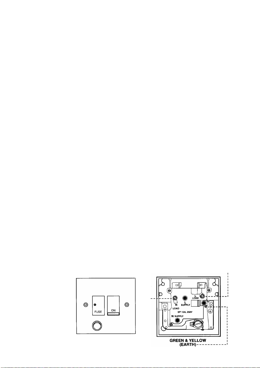
Appliances Your appliance must be connected to fixed wiring via the use of
with 3 wires a double pole swiched fused spur outlet with or without pilot lamp.
We strongly recommend the appliance is connected by a quali
fied electrician who is a member of the NICEIC who will comply
with the I EE and any local regulations.
NOTE: The terminology “DOUBLE POLE” means that both
the live and neutral supplies are swiched and disconnected at
the same time.
The terminations labelled SUPPLY are for the connection for the
internal house wiring and the terminations labelled LOAD are for
the appliance.
WARNING: THIS APPLIANCE MUST BE EARTHED
IMPORTANT
The wires in this mains lead are coloured in accordance with the
following code:
Green/Yeiiow - Earth
Blue - Neutral
Brown - Live
As the colours of the wires in the mains lead of this appliance may
not correspond with the coloured markings identifying the termi
nate in your spur box, proceed as follows:
The wire wbii^% coloured green and yellow must be connected
to the terminal which is marked with the letter “E” or by the earth
symbol ^ or coloured green or green and yellow. The wire which
is coioured blue must be connected to the terminal which is
marked with the letter “N” or coloured black.
The wire which is coloured brown must be connected to the
terminal which is marked with the ietter “L” or coloured red.
12
-BLUE
BROWN
(LIVE)--
Page 13

Installation
Before fixing the furniture door to the hood, please ensure the
correct distance between the plate and the upper edge of the
cabinet door (depends on the thickness of the material and
whether or not there is an upper shelf) (Fig. 6).
1. Remove the grille filter C by turning the locks D and pull it out
downwards (Fig. 3).
2. Take off the extendable vapour guide G (fig. 7) by turning the
rear locking knobs H (Fig. 7).
3. Draw a line with a pencil on the middle of the internal side of the
furnituture door (Fig. 8).
4. Fit the plate upon the internal side of the furniture door so that
the line previously marked on it, is visible through the two
triangles holes located on the mid upper and lower side of the
plate, having care to respect the distance from the plate to the
higher edge of the furniture door as for the reason mentioned
above.
5. Fasten the plate to the furniture door through the 6 screws L 4,5
X 13 mm supplied (Fig. 8).
6. Replace the complete fume protection plate assembly into the
extractor hood, first inserting it on its upper, then on its lower
guides.
7. Turn the rear unlocking knobs H (Fig. 7) so to avoid the fume
protection plate take off.
8. Replace the grille filter.
1. Remove the grille filter (Fig. 3).
2. Remove the fume protection plate (Fig. 7).
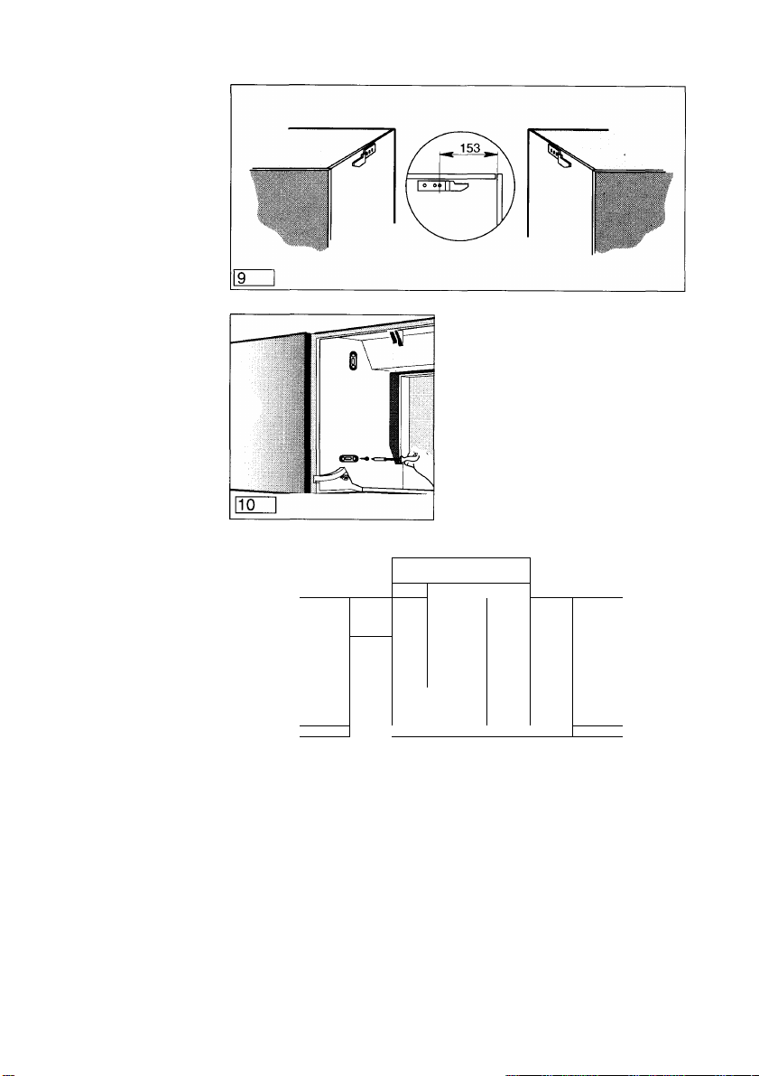
3. Mount the two hanging rails directly underneath the edge of the
cupboard using three screws 4,5 x 16 mm each rail.
Distance from first hole to front edge of the cupboards sides
must be 153 mm (Fig. 9).
4. Push the extractor hood over the two hanging rails, then fix the
hood from its inside to the cupboards sides with two screws (4,5
X 13) through the lower holes of the hood (Fig. 10).
5. Replace the the complete fume protection plate assembly into
the extractor hood.
6. Replace the grille filter. •
7. Ensure that there is not a gap between the back of the hood and
the wall by adjusting the spacer M tightly to the wall, using the
screws O (fig. 12).
Fixing the
furniture
door to the
hood
Installing the
hood between
cupboards with
hanging rails
13
Page 14

Installing the hood
to the wall
It is possible to fix the hood in position, if necessary, by only
attaching it to the rear wall.
Proceed as follows:
1. Drill the four holes on the wall as indicated (Fig. 11).
2. Insert the four rawl plugs supplied into these holes.
3. Screw the two mountings hooks into the top two rawl plugs
(Fig. 12).
4. Dismount the spacer M (Fig. 12) from the body of the hood by
unscrewing completely the two spacer fixing screws O and
washers.
5. Fix the base spacer M to the wall (Fig. 12) with the two screws
R 5x45 provided (Fig. 11) using either the long or the short arm,
depending on the depht of the side cupboards.
Do not tighten the screws fully.
6. Fix the hood to the wall by means of the two hooksP previously
mounted, but first move the upper brackets S (Fig. 11) so that
the front panel of the hood, once mounted, will be in line with
the front edge of the cupboard doors. The two upper brackets
S, located at the top rear edge of the hood may be slid
backwards and forwards by loosening its fixing screws T
adjacent to them on the upper hood surface (Fig. 11).
7. Check that the hood is at the right height. Minor height
adjustments may be made with the screws U embodied in the
brackets (see Fig. 11).
8. Tighten the two wall fixing screws R, through the two access
holes N provided on the inside of the hood (Fig. 12) then fix the
lower sliding frame to the hood with two screws O and washers
previously unscrewed (item 4).
14
Page 15

Using the hood
It is advisable to switch on the cooker hood a few minutes before
starting cooking and then to leave it running fot approximately 15
minutes afterwards to ensure that all odours are extracted.
On the front of the appliance there are control switches
(see page 3).
The switch marked with motor symbol controls fan power.
The switch marked with lamp symbol controls the lighting of the
cooking surface.
The hood is also fitted with an automatic micro switch located on
the right hand side behind the visor, the micro switch will switch
the hood OFF, whatever selection is made with the slider switches
when the visor is closed. When the visor is pulled open the hood
will switch ON at its previous setting.
— If the hood is run at the same time as an ambient-air dependent
burner or fireplace (for example gas, diesel, coal or wood
heaters, water heaters, etc.) be careful, because the hood,
when it extracts air, removes the ambient air the burners of
fireplace need for combustion.
For safe operation and to prevent discharged gas from coming
back into the room, make sure there is an air inlet, which may be
provided through air-recycling doors, windows or wall boxes or
by other technical devices.
— No food must be cooked flambé underneath the hood. The
use of an unprotected flame is dangerous for the filters and
could cause a fire. Therefore never use an open flame under
the hood. When frying foods, never leave the pan unattended,
the cooking oil could ignite. If contaminated oil is used,
spontaneaous ignition may occur even more readily.
— The hood must not be connected to fuel exhaust flues
(boilers, heating systems, water heaters, etc.).
— The manufacturers do not accept liability for damage to the
hood or its catching fire because of failure to observe the
above instructions.
Where flexible ducting is fitted the length should be no more
than:
— 3 metres with one 90° bend
— 2 metres with two 90° bends.
Bends of more than 90° will reduce the efficiency of the hood
and reduce the air flow.
15
Page 16

Maintenance
Before carrying out any maintenance disconnect the hood from the electricity supply.
Grease filter
Removing the
grease filter
Carbon filter
The grease filter traps the suspended grease particles, and is
used in the hood regardless of whether the hood is in the
extraction or recirculating mode.
The thin synthetic filter (thickness about 1 mm) is installed inside
the filter grille. It is changed when the top colouring appears on the
bottom, i.e. you can see the colour through the filter grille.
To remove the filter:
a) Remove the filter grille (see fig. 3)
b) Take out the saturated filter after removing the clamps
Z (fig. 13).
c) Fit a new grease filter and replace filter grille.
When replacing the grease filter, also wash the filter grille with
warm water and mild detergent i.e. washing-up liquid.
Replacement grease filters are available from AEG Spare Parts
- Telephone (0753) 872550.
The carbon filter is fitted when the hood is used in the recirculating
mode.
This is not washable and cannot be reused.
The carbon filter should be replaced at least once every four
months.
Removing the
carbon filter
Cleaning
16
To remove the carbon filter, push the push-buttons E inwards and
pull the filter downwards (Fig. 4).
Please specify model number and product number when ordering
a replacement filter. This is found on the rating place located
inside the hood. Replacement filters are available from AEG
Spare Parts, Telephone (0753) 872550.
To clean the outside of the hood use a mild solution of washingup liquid and water.
Never use abrasive detergents, brushes or scouring powders.
Important
Always switch off the hood and pull out the plug before
cleaning.
Page 17

ATTENTION
Failure to observe the rules for cleaning the appliance and
changing and cleaning the filters may cause a fire as a result of
grease deposits. Therefore please observe these
recommendations.
1) Disconnect the hood from the electricity supply.
2) Remove the filter grille (fig. 3) - this will then allow inspection/
change of the bulb/s.
3) Unscrew defective bulb and replace with new one. Important:
always use 40W candle lamp (El 4) bulbs.
Before calling the Service Engineer because the hood fails to light
up, make sure the bulbs are screwed in tightly.
Dimensions
Height — 400mm
Width — 599mm
Depth —270mm
Weight
Net 9,7Kg
Connected Load 200W
Fan Motor 120 W
Lighting: 40 Watt Candle Lamp x 2
Lengt of the cable: 140 cm
Changing the
bulbs
Technical Data
Fan speed: 1
Extractor version: 143 m%
Filtre version: 87 m^/h
Special Accessories
Wall/Window Box
Venting Hose 120mm x 2.4M
Venting Hose 100mm x 2.4M
Universal Grease Filter
Carbon Filter KLF 60/80
171 mVh
132 mVh
Number
Performance
Data
234 mVh
167 mVh
647 000 020
647 000 012
647 000 010
660 951 157
610 899 421
17
Page 18

Faults
In case of any enquiries and faults, please call AEG After-Sales Service;
AEG Domestic Appliances Limited Head Office:
217 Bath Road
Slough, Berks SL1 4AW
Tel: 01753 872506
Telefax: 01753512271
AEG Northern Service Centre: AEG Scottish Service Centre:
Unit 20, Haigh Park
Haigh Avenue
Stockport
GL Manchester SK4 1QR
Tel: 0161 487 2205
Telefax: 0161 474 1191
Service Appointments
Bristol: 01179 252880
Norfolk: 01603 765515
When calling please state the following
1. The model number
Block 11, Unit 1
Dundyvan Industrial Estate
Coatbridge
Lanarkshire ML5 4AQ
Tel: 01236 440387
Telefax: 01236 440256
2. The E-Nr.
3. The F-Nr.
The manufacturer reserves the right to make alterations in design
and colour in the interests of technical development without prior
notice.
18
Page 19

AEG Hausgeräte AG
Postfach 1036
D-90327 Nürnberg
© Copyright by AEG
H 260 251 240
L361C Ed.06/95
 Loading...