

Page 1

2600 D
Cooker hood
Operating and Installation Instructions
Page 2
Contents
Safety instructions ..................................................... 2
Description of the cooker hood ................................... 3
Using the cooker hood ............................................... 4
Maintenance and cleaning.......................................... 6
What to do if .............................................................. 8
Service and Spare Parts ............................................ 9
Customer Care........................................................... 9
Guarantee Conditions............................................... 10
T echnical data.......................................................... 1 1
Installation ............................................................... 12
Safety instructions
These warnings are provided in the interest of your safety.Ensure that you
understand them all before installing or using the appliance. Your safety is of
paramount importance. If you are unsure about any of these meanings or
warnings contact the Customer Care department
Please retain this instruction book for future reference, particularly if the
appliance is sold or left to another person.
Installation and service
● Any electrical installation of the cooker hood m ust be carried out by a
qualified electrician and the hood itself must be installed by someone
with experience. Installation made by an unqualified person can lead to
loss of function of the cooker hood and possible damage to person and
and/or property.
● The cooker hood must be at least 50 cm above electric hobs or electric
ranges, or at least 65 cm above gas burners or gas ranges.
● Ensure that the power cable is not damaged during installation.
● The cooker hood is only in stand by mode unless the plug or the fuse is
disconnected.
● The cooker hood cannot be connected to flues of other appliances that
run on energy sources other than electricity . Please , keep to the
provisions of official directives regarding fume discharge.
2
Page 3
Use of cooker hood
● This appliance is for domestic use only in a normal household.
● Never leave any deep-frying, melting fat, paraffin or any other
inflammable liquid unattended on the hob. In the event of fire:
Immediately switch off the cooker hood and the cook er . Note! Cover
the fire. Never use water.
● Never do any flambé cooking underneath the cooker hood. It can cause
a fire. Remember that overheated fat may spontaneously ignite. Never
leave the frying pan unattended.
● It is essential that the grease filter is regularly cleaned to help avoid fat
dripping on to the hot zone and causing a fire. Read the section on
“Maintenance and Cleaning” in the instruction book.
Disposal
● Prevent accidents when disposing of your cooker hood. Disconnect the
power plug from the wall socket and cut the power cord at the hood
inlet.Contact your local authority for information on where to dispose the
cooker hood.
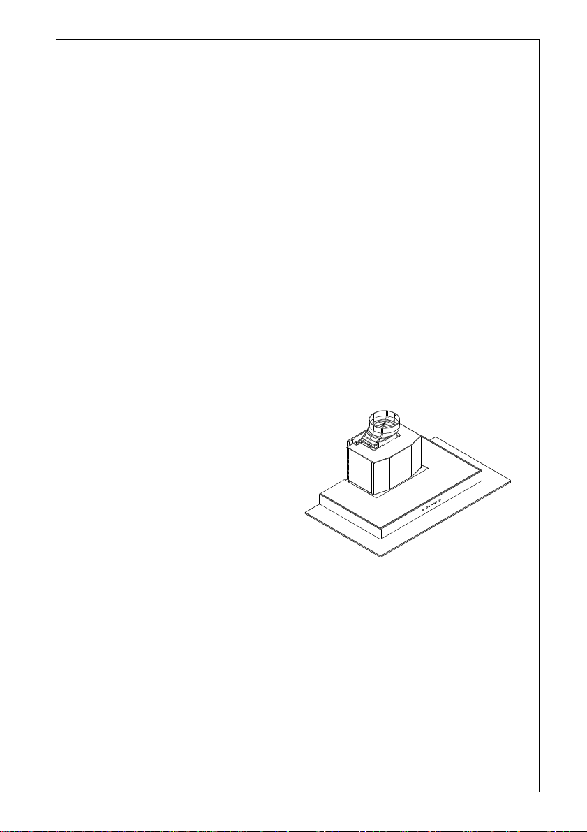
Description of the cooker hood
Functions
There are two possible systems:
● Extraction of air to the outside using an
optional venting kit and evacuation
duct.
● Recirculation using an optional
carbon filter.
Accessories
The following are included with the cooker hood.
● 1 Adaptor 150-125 mm
● 2 Tube clamps
● 1 hood canopy complete with controls, lighting and f an motor .
● 1 telescopic chimney stack formed by: U-shaped upper section and U-
shaped lower section.
● 1 reduction flange Ø 150-125 mm.
● 1 recirculation spigot.
● 1 plastic bag containing: 2 wall hooks to fix the canopy hood, 1 wall
bracket to fix the chimne y, rawl plugs , screws, and documentation.
The following can be ordered from your retailer:
● Carbon, KF8 filter, alternatively KFL 60/80. The carbon filter is to be used
when the hood is connected to the recirculation mode.
Fig. 1
3
Page 4
Using the cooker hood
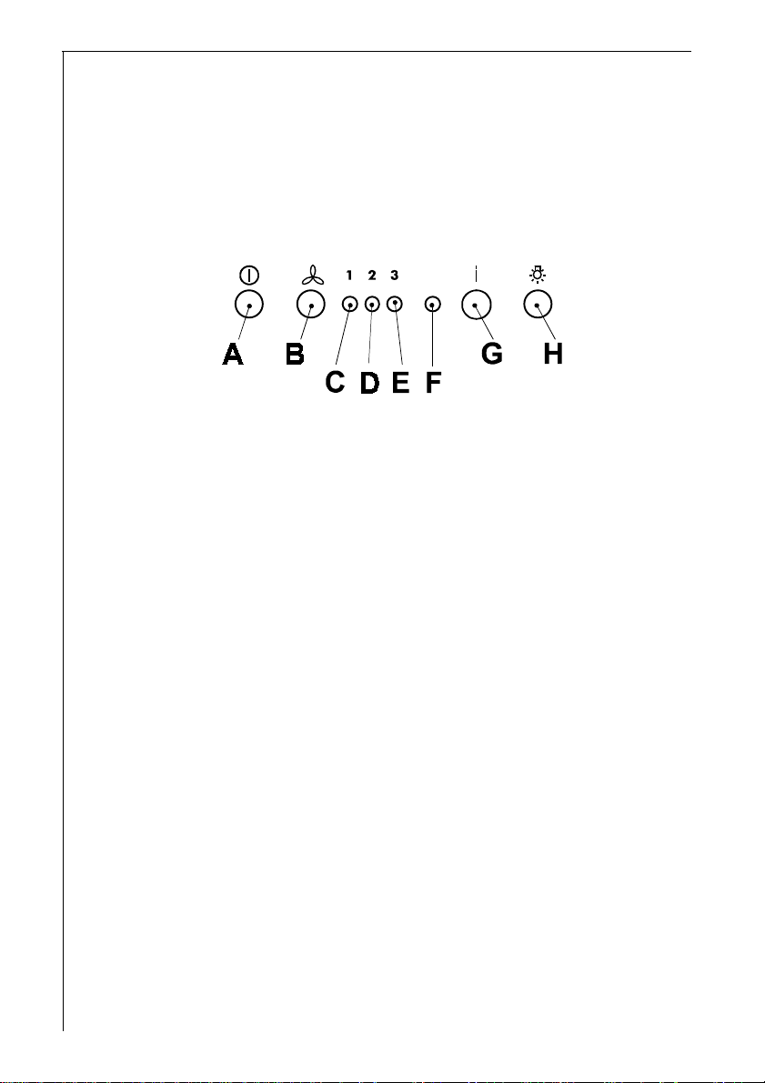
The control panel
Best results are obtained by using a low speed for normal conditions and
high speed when odours are more concentrated.
Turn the hood on a few minutes before you start cooking then you will get
an underpressure in the kitchen. It should be left on after cooking for about
15 minutes or until all odours have disappeared.
Fig. 2
A - Main switch, hood on/off.
B - Start and choice of motor speed 1-2-3-1-2.........
C - Indicates speed 1 (LED) and indication of the grease saturation
for the filter (flashing indicator).
D - Indicates speed 2 (LED) and indication of the charcoal saturation
for the filter (flashing indicator).
E - Indicates speed 3 (LED)
F - Indicates Intensive speed (LED).
G - Intensive speed on/off. The Intensive speed runs for 5 minutes:
If the hood is on when the Intensive speed is activated, the hood
reverts to previous speed after 5 minutes.
If the hood is off when the Intensive speed is activated, the hood
will be turned off after 5 minutes.
T o interrupt the Intensive speed, press button A or B.
H - Light ON/OFF
Correct ventilation
If the cooker hood is to work correctly there must be an underpressure in
the kitchen. It is important to keep the kitchen windows closed and have a
window in an adjacent room open.
Important to know
Not applicable for recirculation. Great care must be taken if the hood is
used at the same time as a burner or fireplace (e.g. gas, diesel, coal or
wood heaters, water heaters, etc.), as the hood will expel air which is
required by these other appliances. Attend to it b y opening a window . The
negative pressure in the room must not exceed 0,04 mbar to prevent fumes
being drawn back into the room by the cooker hood.
4
Page 5

LED Indicator lights for verifying the saturation
of filters
This hood is supplied without a charcoal filter. If the hood is to be used
in the recirculation mode with a charcoal filter, the saturation indicator
must be activated as follows:
Depress and hold the A and B buttons simultaneously for 3 seconds.
Initially only the LED indicator signal for the grease filter C is activated,
shortly after the LED indicator for the charcoal filter D will activate, at
this point the saturation detection has been enabled.
To switch off the saturation detection : depress and hold the A and B
buttons for 3 seconds until the LED indicator for the active carbon filter
is flashing.
Led – Indicator for grease filter C
The LED indicator for the grease filter will flash when it requires
cleaning.
Follow the maintenance instructions.
Led - indicator for charcoal filter D
The LED indicator for the charcoal filter illuminates when the filter
requires replacing.
This occurs after about 160 working hours from when the active carbon
filter was first put into operation.
Resetting the saturation indicator
After cleaning or replacing the filter depress and hold the G and H
buttons again for 3 seconds until the grease filter LED or the charcoal
indicator LED are no longer flashing.
5
Page 6

Maintenance and cleaning
Before doing any maintenance work on the hood, disconnect it
from the main supply by disconnecting the plug from the wall
socket or unscrewing the fuse.
Cleaning the hood
Clean the outside of the hood using a damp cloth and a mild detergent.
Never use corrosive, abrasive or flammable cleaning products.
Cleaning the grease filters
Clean the filter every month or every
other month according to how much
the hood is used. The cleaner the
filters, the more grease they collect.
Remove the filters by (Fig. 3):
● Push the handle towards the rear
of the hood.
● Pull the filter down at the front
and remove it forwards.
The filter is made of aluminium wires
on which the grease collects. Clean
the filter in hot water using a detergent,
or in a dishwasher. Let the filter dry
before putting it back. Note that a
dishwasher may discolour the filter.
Fig. 3
Changing and cleaning the carbon filter
Only applicable for recirculation. The carbon filters absorb smells and
odours.
Unlike other carbon filters, the LONGLIFE carbon filter can be cleaned and
reactivated. At normal use the filter should be cleaned every second month.
The best way to clean the filter is in the dishwasher. Use normal detergent and
choose the highest temperature (65º C). Wash the filter separately so that no
food parts gets stuck on the filter and later causes bad odours. To reactivate
the carbon, the filter should be dried in an oven for 10 minutes with a
temperature of maximum 100º C.
The KFL 60/80 carbon filter can not be reactivated, it has to be changed after
6-8 months of normal use.
6
Page 7

After approximately three years of use, the KF8 filter should be replaced with
a new, as the odour reduction capacity will be reduced.
T o remo ve the filter (Fig. 4):
● Remove the grease filters.
● Press the red buttons (A), lower the front of the carbon filter.
● Remove the carbon filter .
● Replace in reverse order .
A A
Fig. 4
Clean the filters regularly . The grease that collects in the filters
and the duct could ignite if a hot plate is left on (or if overheating
occurs).
Remove the upper glass panel
The upper glass panel can be removed for cleaning (Fig. 5):
● Remove the grease filters
● Pull the handle L down
● Remove the glass panel
L
Fig. 5
Changing the light
Disconnect the cooker hood from the main supply before changing the light.
To change the light (Fig. 6):
● Remove the lamp cov er, use a screw driv er.
● Replace the old bulb with a new one of the same type.
● Remount the lamp cover .
Fig. 6
7
Page 8

What to do if
If your appliance fails to work properly please carry out the following checks.
Symptom Solution
The cooker hood will not start... Check that:
The hood is connected to the
electricity supply.
Check that the fan speed control is
set to 1, 2 or 3.
The cooker hood is not working Chec k that:
effectively.. The fan speed is set high enough
. for the task.
The grease filters are clean.
The kitchen is adequately vented to
allow the entry of fresh air.
If set up for recirculation, check that
the charcoal filter is still effective.
If set up for extraction, check that
the ducting and outlets are not
blocked.
The cooker hood has switched off The safety cut-out device has been
during operation... tripped.
Turn off the hob and then wait for the
device to reset.
If the hood has been installed below
the heights indicated in the
installation instructions the motor
will cut-out frequently which will
damage the hood.
If after all these checks, the problem persists, contact your local Service
Force Centre, quoting the model and serial number.
Please note that it will be necessary to provide proof of purchase for any
in-guarantee service calls.
In-guarantee customers should ensure that the above checks have been
made as the engineer will make a charge if the fault is not a mechanical or
electrical breakdown.
8
Page 9

Service and spare parts
In the event of your appliance requiring service, or if you wish to
purchase spare parts, contact your local AEG Service Force Centre by
telephoning
08705 929 929
Y our call will be automatically routed to the Service Centre covering
your post code area.
For the address of your local Service Force Centre and further information about Service Force, please visit the website at
www.serviceforce.co.uk
Please ensure that you have read the section „What to do if....“ as the
engineer will make a charge if the fault is not a mechanical or electrical
breakdown even the appliance is under warranty .
Please note that proof of purchase is required for in-guarantee
service calls.
Help us to help you
Please determine your type of enquiry before writing or telephoning.
When you contact us we need to know:
• Your name
• Address and post code
• T elephone number
• Clear and concise details of the fault
• Name and model of the appliance*
• E number*
* This information can be found on the rating plate, which can be seen
when the grease filters are removed.
Customer Care
For general enquiries concerning your AEG appliances, or for further
information on AEG products, please contact our Customer Care
Department at the address below or visit our website at www.aeg.co.uk
Customer Care Department
AEG Domestic Appliances
55-77 High Street
Slough
Berkshire
SL1 1DZ
T el.: 08705 350 350*
* calls to this number may be recorded for training purposes.
9
Page 10

Guarantee conditions
Guarantee Conditions
AEG offer the following guarantee to the first purchaser of this appliance.
1. The guarantee is valid for 12 months commencing when the appliance
is handed over to the first retail purchaser, which must be verified by
purchase invoice or similar documentation.The guarantee does not
cover commercial use.
2. The guarantee covers all parts or components which fail due to faulty
workmanship or faulty materials. The guarantee does not cover
appliances where defects or poor performance are due to misuse,
accidental damage, neglect, faulty installation, unauthorised
modification or attempted repair, commercial use or failure to observe
requirements and recommendations set out in the instruction book.This
guarantee does not cover such parts as light bulbs, removable glass-
ware or plastic.
3. Should guarantee repairs be necessary the purchaser must inform the
nearest customer service office (manufacturer`s service or authorised
agent). AEG reserves the right to stipulate the place of the repair
(i.e.the customer`s home, place of installation or AEG workshop).
4. The guarantee or free replacement includes both labour and materials.
5. Repairs carried out under guarantee do not extend the guarantee
period for the appliance. Parts removed during guarantee repairs
become the property of AEG.
6. The purchaser`s statutory rights are not affected by this guarantee.
European Guarantee
If you should move to another country within Europe then your guarantee
moves with you to your new home subject to the following qualifications:
- The guarantee starts from the date you first purchased your product.
- The guarantee is for the same period and to the same extent for labour
and parts as exist in the new country of use for this brand or range of
products.
- This guarantee relates to you an cannot be transferred to another user.
- Y our new home is within the European Community (EC) or European
Free Trade Area.
- The product is installed and used in accordance with our instructions
and is only used domestically , i.e. a normal household.
- The product is installed taking into account regulations in your new
country.
10
Page 11

Before you move please contact your nearest Customer Care Centre, listed
below, to give them details of your new home.They will then ensure that the
local Service Organisation is aware of your move and able to look after you and
your appliances.
France Senlis +33 (0) 3 44 62 29 29
Germany Nürnberg +49 (0) 800 234 7378
Italy Pordenone +39 (0) 800 117 511
Sweden Stockholm +46 (0) 8 672 5360
UK Slough +44 (0) 1753 219899
Technical data
Model 2600 D
Size Height 800-1225 mm
Width 898 mm
Depth 520 mm
Light Max 2X20 W
Grease filter 2 pcs.
V oltage 220-240 V
T otal pow er 175 W
Fuse Rating 13 Amp
Extra accessories:
Carbon filter KF 8 (LONGLIFE) P-nr. 942 118 609
Carbon filter KFL 60/80 610 899 421
11
Page 12

Installation
Unpacking
Check that the cooker hood is not damaged. Transportation damages
should immediately be reported to the transport company. Damages, f aults
and missing parts should immediately be reported to the retailer.
Dispose carefully of the packaging material so that it is out of the way of
small children.
Position
The cooker hood should be mounted freely hanging on the wall. The
cooker
hood must be at least 50 cm above electric hobs or electric ranges, or at
least 65 cm above gas burners or gas ranges.
The cooker hood cannot be connected to flues of other
appliances that run on energy sources other than electricity.
Please, keep to the provisions of official directives regarding fume
discharge.
Electrical connection
The electric outlet should be placed inside the chimney.The hood has a
power cable, 100 cm, with earth connection and the rated voltage is
220 - 240 V.
Connect the hood to the mains supply via a double pole switch
which has 3 mm minimum clearance between the contacts 220-240 V.
The following is valid in the United Kingdom only:
As the colours of the wires in the mains lead of this appliance may not
correspond with the coloured markings identifying the terminals in your plug,
proceed as follows:
- the wire which is coloured green and yellow must be connected to the
terminal in the plug which is marked with the letter E or by the earth
symbol ( ), or coloured green or green and yellow;
- the wire which is coloured blue must be connected to the terminal which
is marked with the letter N or coloured black, -
- the wire which is coloured brown must be connected to the terminal
which is marked with the letter L or coloured red.
12
Page 13

Mounting the cooker hood - Fig. 8
● Position the template (1) on the wall and mark the position, and drill the
holes (2 x Ø 8 mm).Mount the two rawl plugs with the hooks (3)
● Hang the hood on the hooks and level it with the adjustment screws (4)
● Remove the grease filters (5) and mark for the two screws (6). Remove
the hood and drill the holes (2 x Ø 8 mm).
● Insert the rawl plugs (7) and hang the hood on the wall again. Adjust it
horizontally with the screws (8) and secure it with the screws (9)
● Mount the chimney holder (10) with the rawl plugs (9a) and the screws
(11).
Be careful that it is centered over the hood and horizontally aligned.
Fitting for ducting (S)
Connect a tube between the hood air outlet and the wall or roof exhaust
channel. Fix it with the tube clamps supplied.
Fitting for recirculation
Mount the recirculation spigot (12) with the two screws (13) supplied.
Mounting the chimney
● Place the chimney and fix it to the top chimney holder with the two
screws (16) supplied.
● Lower the bottom part of the chimney and fasten it to the top of the
hood with two screws (17), supplied.
Note that the top part of the chimney can be mounted with the side grids up
or down. For use as a recirculation hood it must be mounted with the grids
upwards. (Fig. 7).
Fig. 7
13
Page 14

a
a
S
Fig. 8
14
Page 15

Electric hob 500 mm
Gas hob 650 mm
Charcoal and oil 700 mm
Exhaust tube
Power outlet
Wall bracket
Electric hob 500 mm
Gas hob 650 mm
Charcoal and oil 700 mm
Fig. 8a
15
Page 16

AEG Hausgeräte GmbH
Postfach 1036
D-90327 Nürnberg
http://www.aeg.hausgeraete.de
© Copyright by AEG
LI1LLD Ed. 05/02
 Loading...