

Page 1

240 D
Dunstabzugshaube
Hotte aspirante
Afzuigkap
Cooker Hood
Montage- und Gebrauchsanweisung
Manuel de montage et d’utilisation
Installatie- en gebruksaanwijzing
Operating and Installation Instructions
Page 2
Printed on recycled paper
AEG - putting words into action
68
Page 3
Contents
Introduction 70
Extractor version 70
Filter Version 71
Summer/Winter Hood Conversion 71
Electrical connection 72
Safety warnings 72
Technical Details 73
Installation 74
Safety warnings 74
Wall unit mounting 76
Wall mounting 76
Hood Operation 77
Setting the fan speed 78
Hood lighting 78
Intensive speed “P” 78
Fan timer 79
Switching off the fan 79
Hood operation before and after cooking 80
Warnings on the activated carbon filter 80
Display warning on saturation of activated carbon filter 81
Open the metal grease filter 82
Display warning on saturation of metal grease filter 83
Safety Warnings for user 85
Maintenance and care 86
Attention 86
Changing the light bulb 86
Cleaning 86
Special accessories 87
Technical assistance service 87
69
Page 4
Introduction
Extractor version
• The hood is supplied as an extractor unit and can also be used with
a filtering function by fitting one activated carbon filter (special
accessory).
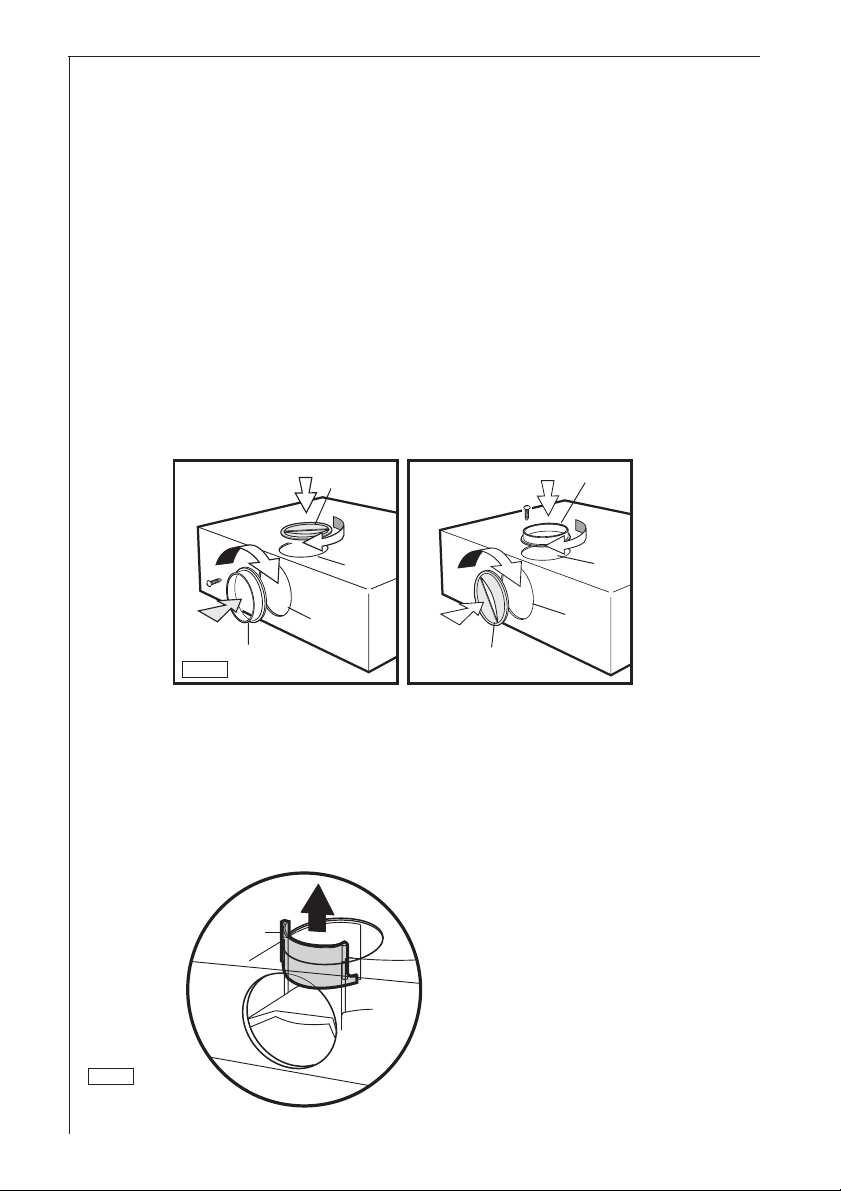
• The unit features two outlet holes, one of which A is located on the
top of the unit while the other B is located on the rear.
• To connect up the hose, you should first fit the bayonet-mounting
flange C (Ø 120 mm) on the outlet required (if using the top outlet,
fix the flange in place using the screw supplied as shown in Fig. 1).
Close off the unused hole using the bayonet fitting caps D.
1
D
2
5
1
4
3
C
A
B
3
5
4
D
C
1
2
A
B
• Important! To use the back hole B, remove switch F from the top
hole. See Fig 2.
F
2
A
B
70
Page 5
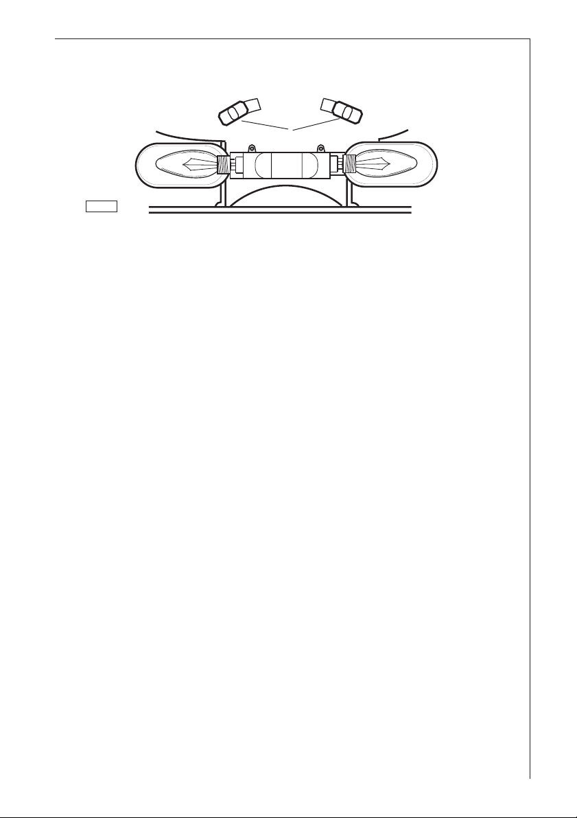
• Move the lever L to position A - Fig. 3.
F
A A
L
3
• When connecting up the hood using a telescopic wall pipe, you
should use an inflammable outlet hose ABS 120 (120 mm Ø) E-Nr.
942 118 611 available as an accessory.
Filter Version
• The air is filtered and recirculated through the front grid.
• Move the lever L to position F - Fig. 3.
You will need original AEG KFF activated carbon filter for this
function (see Special Accessories).
Summer/Winter Hood Conversion
• To avoid excessive heat loss during the winter months, we
recommend that the hood be converted from extractor version to
filter version.
• In order to convert the hood, a activated carbon filter (available as
an accessory) is required. Follow the instructions for operating the
hood to recirculate air.
• When the temperature outdoors becomes more mild (spring), the
filter can be removed and the hood converted once again for to
extraction. Please consult the assembly instructions for operating
the hood in extractor version.
71
Page 6
Electrical connection
Safety warnings for the electrician
Before connecting the appliance to the power supply, check that the
voltage indicated on the rating plate corresponds to the mains power
supply available. Appliances fitted with a plug can be connected to
any standard power socket within easy access.
Should it be necessary to provide a fixed connection, the hood must
only be installed by an electrician authorised by the local electricity
board. To isolate the cooker hood from the mains, pull the mains plug.
If the appliance is permanently connected to the mains, then it must
be isolated from the mains using measures provided in the electrical
installation (fuses -unscrew-type fuses, cut-out, current trips or similar
that have a contact separation of >3mm when open).
The manufacture declines all responsibility for malfunctions resulting
from failure to comply with the above instructions.
If the power socket is applied directly above the hood this gives two
advantages:
1. The socket is not visible.
2. The appliance can be disconnected at need merely be removing the
plug.
Electrical connection
220-230 V – by means of fixed power cable with plug.
(Fixed connection of the appliance must only be carried out by an
authorised electrician.)
72
Page 7

Technical Details
Dimensions :
Height x Width x Depth (in cm) 13 x 59,9 x 51
Weight:
Net: 8,7 kg
Gross: 9,7 kg
Maximum absorbed power: 330 W
Motor absorption: 2 x 125 W
Lighting: 2 x 40 W
Length of the cable: 110 cm
Fan powers (speed), speed in compliance with DIN 44971
(Extractor version) Speed:
min. 131 m3/h
max. 251 m3/h
intensive 360 m3/h
(Filter version) Speed:
min. 50 m3/h
max. 125 m3/h
intensive 140 m3/h
Flange 120 mm Ø
73
Page 8

Installation
Safety warnings for kitchen unit installer
• When used as an extractor unit, the hood must be fitted with a
120mm diameter hose.
• If the fumes must be forced out through the wall, you must obtain a
MKZ sizable wall exhaust pipe (with external exhaust and air
intake), E-Nr.- 610 899 004 (Ø 120 mm) which is one of our optional
parts.
• When installing the hood, make sure you respect the following
minimum distance from the top edge of the cooking hob/ring
surfaces:
electric cookers 650 mm
gas cookers 650 mm
coal and oil cookers 700 mm min.
• The national decree on fuel-burning systems specifies a maximum
depression of 0.04 bar in such rooms.
• The air outlet must not be connected to chimney flues or combustion gas ducts. The air outlet must under no circumstances be
connected to ventilation ducts for rooms in which fuel-burning
appliances are installed.
• It is advisable to apply for authorization from the relevant controlling
authority when connecting the outlet to an unused chimney flue or
combustion gas duct.
The air outlet installation must comply with the regulations laid down
by the relevant authorities.
• When the unit is used in its extractor version, a sufficiently large
ventilation hole must be provided, with dimensions that are
approximately the same as the outlet hole.
• National and regional building regulations impose a number of
restrictions on using hoods and fuel-burning appliances connected
to a chimney, such as coal or oil room-heaters and gas fires, in the
same room.
• Hoods can only be used safely with appliances connected to a
chimney if the room and/or flat (air/environment combination) is
ventilated from outside using a suitable ventilation hole approximately 500-600 cm2 large to avoid the possibility of a depression
being created during operation of the hood.
• If you have any doubts, contact the relevant controlling authority or
building inspector’s office.
• Since the rule for rooms with fuel burning appliances is “outlet hole
74
Page 9

of the same size as the ventilation hole”, a hole of 500-600 cm2,
which is to say a larger hole, could reduce the performance of the
extractor hood.
• If the hood is used in its filtering function, it will operate simply and
safely in the above conditions without the need for any of the
aforementioned measures.
• When the hood is used in its extractor function, the following rules
must be followed to obtain optimal operation:
— short and straight outlet hose
— keep bends in outlet hose to a minimum
— never install the hoses with an acute angle, they must
always follow a gentle curve
— keep the hose as large as possible (120 mm Ø min.).
• Failure to observe these basic rules will drastically reduce the
performance and increase the noise levels of the extractor hood.
75
Page 10

Wall unit mounting
• Make the holes on the bottom of the cupboard, using the drilling
template.
• From inside the cupboard, insert the 4 supplied screws and tighten
them in the appropriate holes on the appliance. - Fig. 4.
1
2
1
2
4
3
4
3
4
Wall mounting
• Fix the drilling template to the wall.
• Make 3 Ø 8mm holes in the wall 2 at points I, 1 as desired at points
L.
• Insert the three Ø 8mm expansion plugs into the wall.
• Insert two 5x45 screws at points I but do not tighten them
completely.
• Adjust the unit so that it is positioned at a right angle to the wall by
turning the two support screws G.
• Fit the hood into holes I, tighten the 2 screws.
• From inside the hood, insert the third 5x45 screw into hole L. Šee
Fig. 5
2
2
3
2
1
3
1
3
I
L
1
I
L
76
I
L
Fig. 6
5
GG
I
L
CLOSED
OPEN
Page 11

Hood Operation
• The control panel is located on the front of the hood.
The control panel numbers and symbols (Fig. 6 from left to right)
are explained in the key below:
min
6
= Lighting, on/off.
= Fan switch (speeds 1-3).
= Fan timer, 15 minutes.
min
= Display showing fan speed (1-3), high speed (P), change
grease filters (F) and change activated carbon filters (C).
= Decrease fan speed button for reducing speed of motor
from high speed (P) down to speed 1.
= Increase fan speed button for increasing speed of motor
from 1 to 9 and high speed (P).
• If the hood fails to operate correctly, briefly disconnect it from the
mains power supply for almost 5 sec. by pulling out the plug. Then
plug it in again and try once more before contacting the Technical
Assistance Service.
Always press the key before disconnecting the hood from the
mains supply.
77
Page 12

Setting the fan speed
AD
7
• Press the button (F) to select the fan speed from 1 to 3, keeping
it pressed until the speed you want, e.g. speed 3, is shown on the
display (D). The red display LED (D) will come on.
• If you accidentally set a higher speed than you want, press the
decrease speed button (E) until the correct speed is shown on
the display (D).
min
E
F
Hood lighting
• Simply press the button (A) to switch the lighting on or off.
Intensive speed P
C
DE F
min
8
• To select the intensive speed (P), press the increase speed button
(F) until the letter P (high speed) is shown on the display (D).
• Press the button (E) to slow down from intensive-speed
operation. The speeds 9-1 will once again be shown on the display.
78
Page 13

Fan timer
min
• The hood should always be switched on before you start cooking
and left on for approximately 15 minutes after you have finished.
• Press the
min
button (C) to switch on the fan timer.
It will automatically switch off after 15 minutes operation at the
selected speed. A red dot will flash on and off on the display (D).
Switching off the fan
• Press the key (B) to switch off the fan at any speed including P.
B
9
• After 5 seconds the number “0” (Fig. 9) will be shown on the display
(D) followed, finally, by only the red dot. Fig. 10.
D
10
D
min
79
Page 14

Hood operation before and after cooking
• The hood should always be switched on before you start cooking
and left on for approximately 15 minutes after you have finished (fan
min
timer
).
Warnings on the activated carbon filter
• The activated carbon filter should be replaced at least once every
120 operating hours.
• The activated carbon filter cannot be cleaned or reused.
• The effective elimination of cooking odours depends on the
functional adaptation of the volume of activated carbon to the
hood’s air flow and a carefully determined position of the filter inside
the hood.
• This combination inevitably decreases the air flow compared to the
extractor version.
• A decisive parameter for the elimination of cooking odours is what
is known as the “residence time” of the air sucked into the hood in
the activated carbon filter.
• The correct “residence time” can only be obtained using original
AEG activated carbon filters (see Special Accessories).
80
Page 15

Display warning on saturation of activated
min
carbon filter
• After 120 operating hours, the letter (C) (activated carbon filter) will
flash on and off on the display (D) in alternation with the fan speed
setting.
B
11
• This means the activated carbon filter needs to be changed! (This
operation should be carried out every 120 operating hours!).
• Warning! The metal grease filters must be cleaned when you
change the activated carbon filter.
• Proceed as follows to remove and change the activated carbon
filter:
• Switch of the fan motor by pressing the button .
D
• Take the precaution of removing the cartridge fuses from their fuse
holders or tripping the automatic circuit breaker to ensure the fan
motor cannot be switched on accidentally.
81
Page 16

CLOSED
OPEN
L
Open the metal grease filter
• Open the latch L and swing the
grill downwards. (Fig. 12).
• To remove the grid, pull it
forwards from the right
and release it.
12
• Mounting – Fig. 13
a. Fit first rearwards on the proper seats.
b. Then fix frontwards the carbon filter using hooks C.
The activated carbon filter cannot be cleaned or reused.
Clean the inner housing using a hot detergent solution only (never
use caustic detergents, abrasive powders or brushes).
• Dismounting:
Unhook the carbon filter from its housing pushing hooks C.
13
C
C
• Always specify the hood model code number and serial number
when ordering replacement filters. This information is shown on the
registration plate located on the inside of the unit.
• The activated carbon filter can be ordered from the AEG Service
assistance.
82
Page 17

• Screw the fuses back in or reset the automatic circuit breaker.
• Proceed as follows to reset the filter saturation display (counter):
Select any fan speed using E or F buttons and then press
the B and F buttons at the same time, continuing to hold
them down for at least 3 seconds until the flashing letter C stops
being shown on the display (D) and then press the button B .
The activated carbon filter display is now ready for use again.
Display warning on saturation of metal grease
filter
• After 30 operating hours the letter (F- grease filters) will flash on
and off on the display (D) in alternation with the fan speed setting.
D
min
14
• This means that the metal grease filters need to be cleaned! (This
operation should be carried out every 30 operating hours!).
• Proceed as follows to remove and clean the metal filters:
• Switch of the fan motor by pressing the button .
• Take the precaution of removing the cartridge fuses from their fuse
holders or tripping the automatic circuit breaker to ensure the fan
motor cannot be switched on accidentally.
83
Page 18

M
• Open the latch L and swing the grille
downwards. (Fig. 12).
• To remove the grid, pull it forwards
from the right and release it.
• Remove the stops M to take out the
filter. (Fig. 15).
• Clean the inner housing using a hot
detergent solution only (never use
caustic detergents, abrasive
powders or brushes).
• Hand washing
Soak grease filters for about one
hour in hot water with a greaseloosening cleaner, then rinse off
thoroughly with hot water. Repeat the process if necessary. Refit the
grease filters when they are dry.
Dishwasher machine
Place grease filters in dish washer. Select most powerful washing
programme and highest temperature, at least 65°C. Repeat the
process.
When washing the metal grease filter in the dishwasher a slight
discoloration of the filter can occur.
• Wait until the filters are completely dry, then replace them in their
original positions, taking care that there are no gaps between the
two filters.
• Screw the fuses back in or reset the automatic circuit breaker.
• Select any fan speed using the E or F buttons and then press
the B and F buttons at the same time, continuing to hold them
down for at least 3 seconds until the flashing letter F stops being
shown on the display (D) and then press the button B .
15
84
The activated carbon filter display is now ready for use again.
Page 19

Safety Warnings for user
• Always cover lighted elements, to prevent excess heat from
damaging the appliance. In the case of oil, gas and coal fired
cookers it is essential to avoid open flames.
• Also, when frying, keep the deep frying pan on the cooker top/
cooker under careful control.
• The hot oil in the frying pan might ignite due to overheating.
• The risk of self-ignition increases when the oil being used is dirty.
• It is extremely important to note that overheating can cause a fire.
• Never carry out any flambé cooking under the hood.
• Always disconnect the unit from the power supply before
carrying out any work on the hood, including replacing the
light bulb (take the cartridge fuse out of the fuse holder or switch
off the automatic circuit breaker).
• It is very important to clean the hood and replace the filter at
the recommended intervals. Failure to do so could cause
grease deposits to build up, causing a fire hazard.
85
Page 20

Maintenance and care
• The hood must always be disconnected from the mains power
supply before beginning any maintenance work.
Attention
• Failure to observe the instructions on cleaning the unit and
changing the filters will cause a fire hazard. You are therefore
strongly recommended to follow these instructions.
Changing the light bulb
• Disconnect the unit from the mains power supply.
• Open the metal grease filter.
• Replace the faulty lamp with one of equal kind and rating.
• If the light does not come on, make sure the bulb has been
screwed in correctly before contacting the technical assistance
service.
Cleaning
• Warning: always disconnect the hood from the mains power supply
before cleaning it.
Never insert pointed objects in the motor’s protective grid.
• Wash the outside surfaces using a delicate detergent solution.
Never use caustic detergents or abrasive brushes or powders.
• Only ever clean the switch panel and filter grille using a damp cloth
and delicate detergents.
• It is extremely important to clean the unit and change the filters at
the recommended intervals. Failure to do so will cause grease
deposits to build up that could constitute a fire hazard.
86
Page 21

Special accessories
MKZ telescopic wall pipe E-Nr. 610 899 004
Outlet hose ABS120 mm 942 118 611
Carbon filter KKF 942 118 629
Technical assistance service
You are welcome to telephone our technical assistance service (see
list of technical assistance centres) whenever you need information or
in the unlikely event of a fault.
When calling, please be ready to specify:
1. The model code number
2. The serial number (E-Nr.)
3. The manufacturing number (F-Nr.)
This information is shown on the registration plate inside the unit
behind the grease filter.
We reserve the right to change specifications and colours as a result
of our policy of continuing technological development.
87
Page 22

AEG Hausgeräte AG
Postfach 1036
D-90327 Nürnberg
© Copyright by AEG
H 259 246 000
LI1CWB Ed. 06/01
 Loading...