

Page 1

220 D
Dunstabzugshaube
Fume Extractor Hood
Hotte aspirante
Afzuigkap
Cappa aspirante
Montage- und Gebrauchsanweisung
Installation and Operating Instructions
Instructions de montage et mode d'emploi
Montage- en gebruiksaanwijzing
Istruzioni di montaggio ed istruzioni per l'uso
Page 2

Printed on recycled paper.
AEG – putting words into action.
18
Page 3
Contents
Introduction 20
Extractor version 20
Filter version 21
Electrical connections 22
Safety warnings for electrician 22
Technical details 23
Installation 24
Safety warnings for kitchen unit installer 24
Wall unit mounting 26
Wall mounting 27
Hood operation 28
Safety warnings for user 29
Maintenance and care 30
Opening the grid 30
Grease filter 30
Carbon filter 31
Changing the light bulb 32
Cleaning 32
Special Accessories 33
Technical Assistance Service 33
19
Page 4
Introduction
Extractor version
● The hood is supplied as an extractor unit and can also be
used with a filtering function by fitting activated carbon
filters (special accessory).
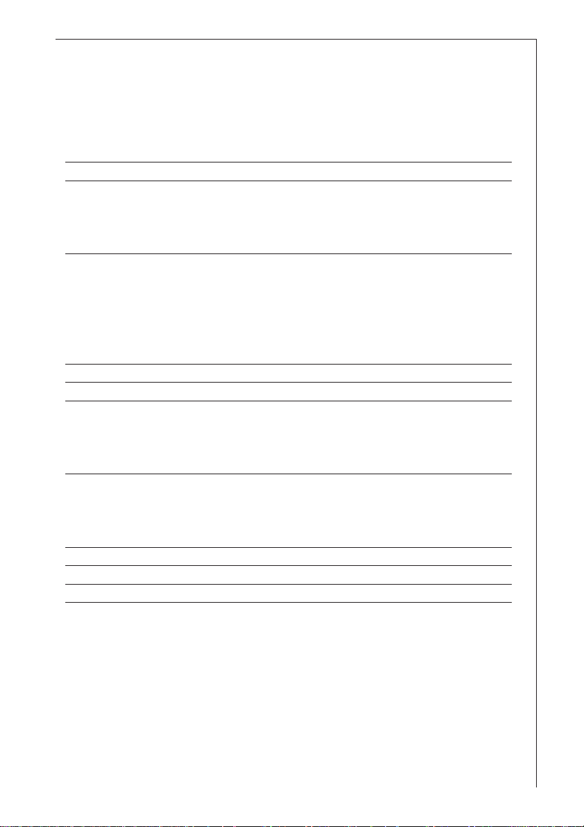
● The unit features two outlet holes, one of which A is
located on the top of the unit while the other B is located
on the rear.
● To connect up the hose, you should first fit the bayonetmounting flange C (Ø120 mm) on the outlet required (if
using the top outlet, fix the flange in place using the screw
supplied as shown in Fig. 1).
Close off the unused hole using the bayonet fitting caps D.
D
A
B
C
1
D
C
A
B
● Important! To use the back hole B, remove switch F from
the top hole. — Fig 2.
F
2
A
B
20
Page 5
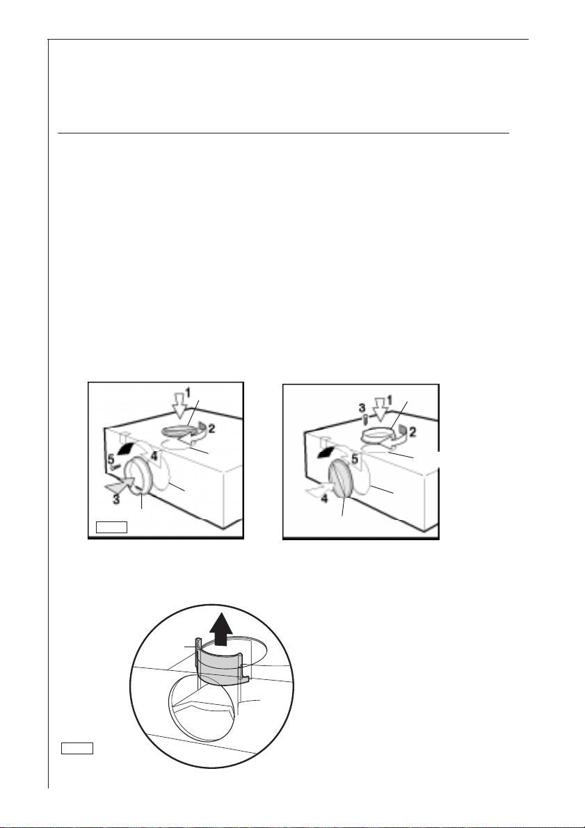
● Move the lever L to position A — Fig. 3.
EXHAUSTING
ABLUFT
A
EVACUATION
ASPIRANTE
RECIRCULATION
UMLUFT
F
RECICLAGE
FILTRANTE
3
L
EXHAUSTING
ABLUFT
EVACUATION
ASPIRANTE
RECIRCULATION
UMLUFT
RECICLAGE
FILTRANTE
A
F
L
● When connecting up the hood using a telescopic
wall pipe, you should preferably using an
uninflammable outlet hose ABS 120 (120 mm Ø)
E-Nr. 942 118 611 from our range of special
accessories.
Filter version
● The air is filtered and recirculated through the front grid.
● Move the lever L to position F — Fig. 3.
You will need an original KFF activated carbon filter for
filtering function. (See special accessories).
Summer/Winter Hood Conversion
● To avoid excessive heat loss during the winter months, we
recommend that the hood be converted from outdoor
ventilation to ventless operation (air recycling).
● In order to convert the hood, a charcoal filter (special
accessory) is required. Follow the instructions for
operating the hood to recycle air.
● When the temperature outdoors becomes more mild
(spring), the filter can be removed and the hood
converted once again for outdoor ventilation. Please
consult the assembly instructions for operating the hood
with outdoor ventilation.
21
Page 6
Electrical connections
Safety warnings for electrician
Check that the power supply voltage shown on the
rating plate corresponds to the mains supply before
proceeding to make any electrical connections. If the unit
is supplied ready-fitted with a plug, it can be connected
to any easily accessible socket installed in compliance
with the regulations in force.
If a fixed connection is required, the hood must be
installed exclusively by an electrician registered with the
local electrical company. The hood should be installed
using an omnipolar switch with contacts that open to at
least 3 mm.
Fused switches can be used for this purpose (with
cartridge fuses that can be extracted from the fuse
holder), as can automatic circuit breakers and contactors
which open to more than 3 mm.
We decline all responsibility for any problems or faults
caused by a failure to observe the above instructions.
Installing the socket directly above the hood or above
the wall unit mounted above the hood offers the
following advantages:
22
1. The socket cannot be seen.
2. The unit can be disconnected whenever required by
simply taking out the plug.
Electrical connections
220-230 V - using fixed power supply line with plug.
(The unit should only be connected up by an authorized
electrician).
Page 7

Technical details
Dimensions:
Height x Width x Depth (in cm) 13 x 59,9 x 51
Weight:
Net: 6,9 kg
Gross: 7,8 kg
Maximum absorbed power: 205 W
Motor absorption 1 x 125 W
Lighting: 2 x 40 W
Length of the cable: 110 cm
Fan powers (speed), speed in compliance with DIN 44971
Extractor version:
1 115 m3/h
2 145 m3/h
3 180 m3/h
i 210 m3/h
Filter version:
1 110 m3/h
2 117 m3/h
3 125 m3/h
i 145 m3/h
Flange:120 mm Ø
23
Page 8

Installation
Safety warnings for kitchen unit installer
● When used as an extractor unit, the hood must be fitted
with a 120mm diameter hose.
● If the fumes must be forced out through the wall, you
must obtain a MKZ sizable wall exhaust pipe (with
external exhaust and air intake), E-Nr.- 610 899 004 (Ø 120
mm) which is one of our optional parts.
● When installing the hood, make sure you respect
the following minimum distance from the top edge
of the cooking hob/ring surfaces:
electric cookers 650 mm
gas cookers 650 mm
coal and oil cookers 700 mm min.
● The hood cannot be connected to flues of other
appliances that run on energy sources other than
electricity.
● The air outlet must not be connected to chimney flues or
combustion gas ducts. The air outlet must under no circumstances be connected to ventilation ducts for rooms in
which fuel-burning appliances are installed.
● It is advisable to apply for authorization from the relevant
controlling authority when connecting the outlet to an
unused chimney flue or combustion gas duct.
The air outlet installation must comply with the
regulations laid down by the relevant authorities.
● When the unit is used in its extractor version, a
sufficiently large ventilation hole must be provided, with
dimensions that are approximately the same as the outlet
hole.
● National and regional building regulations impose a
number of restrictions on using hoods and fuel-burning
appliances connected to a chimney, such as coal or oil
room-heaters and gas fires, in the same room.
24
Page 9

● The national decree on fuel-burning systems specifies a
maximum depression of 0.04 bar in such rooms.
● Hoods can only be used safely with appliances connected
to a chimney if the room and/or flat (air/environment
combination) is ventilated from outside using a suitable
ventilation hole approximately 500-600 cm2 large to
avoid the possibility of a depression being created during
operation of the hood.
If you have any doubts, contact the relevant controlling
authority or building inspector’s office.
● Since the rule for rooms with fuel burning appliances is
“outlet hole of the same size as the ventilation hole”, a
hole of 500-600 cm2, which is to say a larger hole, could
reduce the performance of the extractor hood.
● If the hood is used in its filtering function, it will operate
simply and safely in the above conditions without the
need for any of the aforementioned measures.
● When the hood is used in its extractor function, the
following rules must be followed to obtain optimal
operation:
— short and straight outlet hose
— keep bends in outlet hose to a minimum
— never install the hoses with an acute angle, they must
always follow a gentle curve only
— keep the hose as large as possible (120 mm Ø min.).
● Failure to observe these basic rules will drastically reduce
the performance and increase the noise levels of the
extractor hood.
25
Page 10

Wall unit mounting
● Make the holes on the bottom of the cupboard, using
the drilling template .
● From inside the cupboard, insert the 4 supplied screws
and tighten them in the appropriate holes on the
appliance. — Fig. 4.
1
2
1
2
4
3
4
3
4
26
Page 11

Wall mounting
● Fix the drilling template to the wall.
● Make 3 Ø 8mm holes in the wall. 2 at points I, 1 as
desired at points L.
● Insert the three Ø 8mm expansion plugs into the wall.
● Insert 2 5x45 screws at points I but do not tighten them
completely.
● Adjust the unit so that it is positioned at a right angle to
the wall by turning the two support screws G.
● Fit the hood into holes I, tighten the 2 screws.
● From inside the hood, insert the third 5x45 screw into
hole L. — Fig. 5.
1
3
1
I
L
Fig. 6
5
GG
2
2
3
2
3
I
L
I
L
1
I
L
CLOSED
OPEN
27
Page 12

Hood Operation
● The hood is fitted with a variable speed motor. The most
effective use of the hood is obtained by switching it on a
few minutes before you start cooking and leaving it on a
for approximately 15 minutes after you have finished,
thus ensuring all cooking odours are eliminated. The
control switches are located on the unit’s front panel:
● the light switch switches the hood lamp on and off;
● the motor switch switches the cooking smoke and
vapour extractor motor on and off, enabling you to
select one of the three different speeds and the intensive
speed.
O I O 1 2 3 i
28
Light switch
On/Off
Motor power
adjustable to 3
positions + intensive
Page 13

Safety warnings for user
● Never leave a cooking hob or ring on without a pot or
pan on top of it, to avoid the possibility of excess heat
damaging the unit. Gas, oil or coal cooker flames in
particular should never be left uncovered.
● Special care should be taken when using deep fat
fryers since the oil in them can overheat and burst into
flames.
● The risk of a fat fire increases when using dirty oil.
● It is extremely important to note that overheating can
cause a fire.
● Never carry out any flambé cooking under the
hood.
● Always disconnect the unit from the power
supply before carrying out any work on the
hood, including replacing the light bulb (take the
cartridge fuse out of the fuse holder or switch off the
automatic circuit breaker).
● It is very important to clean the hood and
replace the filter at the recommended intervals.
Failure to do so could cause grease deposits to
build up, causing a fire hazard.
29
Page 14

Maintenance and care
● The hood must always be disconnected from the
mains power supply before beginning any
maintenance work.
Opening the grid
● Open the latch L and swing the grille downwards.
— Fig. 6.
● To remove the grid, pull it forwards from the right and
release it.
M
M
L
CLOSED
OPEN
6
Grease filter
● The purpose of the grease filters is to aspirate grease
particles which form during cooking and it must always
be used, either in the external evacuation or internal
recycling function.
The synthetic filter is very thin (approx. 1 mm) and
positioned on the inside of its related support grille.
The filter should be changed when the fat stains on its
inside surface can be seen through the grille holes.
● The grille should be cleaned with luke warm water and
non-abrasive detergent when you change the filter.
● The grease filter can be ordered from the AEG technical
assistance service.
30
Page 15

Removing the filter
Open the grid and remove the stops M to take out the
filter. See Fig. 6.
Carbon filter
● The activated carbon filter should only be used if you
want to use the hood in its filtering function.
● To do this you will need an original AEG activated carbon
filter (see special accessories).
● This filter cannot be cleaned or reused.
● As a general rule, the activated carbon filter should
be changed once every four months.
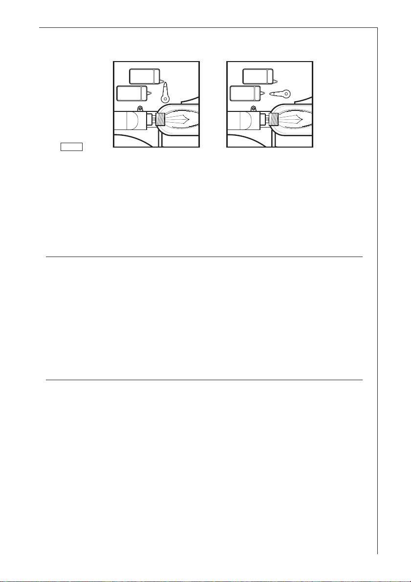
● Mounting – Fig 7
a. Fit first rearwards on the proper seats.
b. Then fix frontwards the carbon filter using hooks C.
● Dismounting :
Unhook the carbon filter from its housing pushing hooks C.
C
7
● Always specify the hood model code number and serial
number when ordering replacement filters. This
information is shown on the registration plate located on
the inside of the unit.
● The activated carbon filter can be ordered from the AEG
technical assistance service.
C
31
Page 16

Warning
● Failure to observe the instructions on cleaning the unit
and changing the filters will cause a fire hazard. You are
therefore strongly recommended to follow these
instructions.
Changing the light bulb
● Disconnect the unit from the mains power supply.
● Remove the grid.
● Replace the old light bulb with a new light bulb (40 W
max.).
● If the light does not come on, make sure the bulb has
been screwed in correctly before contacting the technical
assistance service.
Cleaning
● Warning: always disconnect the hood from the mains
power supply before cleaning it.
Never insert pointed objects in the motor’s protective
grid.
● Wash the outside surfaces using a delicate detergent
solution. Never use caustic detergents or abrasive brushes
or powders.
● Only ever clean the switch panel and filter grille using a
damp cloth and delicate detergents.
● It is extremely important to clean the unit and change the
filters at the recommended intervals. Failure to do so will
cause grease deposits to build up that could constitute a
fire hazard.
32
Page 17

Special accessories
MKZ telescopic wall pipe E-Nr. 610 899 004
outlet hose ABS120 942 118 611
120 mm Ø
Synthetic grease filter 942 118 625
Metal grease filter MFF2 942 118 633
Carbon filter KFF 942 118 629
Technical assistance service
You are welcome to telephone our technical assistance
service (see list of technical assistance centres) whenever you
need information or in the unlikely event of a fault.
When calling, please be ready to specify:
1. The model code number
2. The serial number (E-Nr.)
3. The manufacturing number (F-Nr.)
This information is shown on the registration plate
inside the unit behind the grease filter grille.
We reserve the right to change specifications and colours as
a result of our policy of continuing technological
development.
33
 Loading...