


Contents
Important Notice ...............................................................1
Product Introduction .........................................................1
Safety Precautions ...........................................................1
Charging ...........................................................................3
Use a Battery Indicator to Detect the Battery Level .......................................3
Precautions for Use of the Charger ................................................................4
Specication of the Charger ...........................................................................4
How to Use the Charger .................................................................................4
Precautions for Use of Lithium Battery ..........................................................8
List of Components...........................................................8
Aircraft ..............................................................................10
Guide for Components of the Aircraft ............................................................10
Install Propellers .............................................................................................11
Install Battery ..................................................................................................11
Preparations before Take-off ..........................................................................12
Control the Flight with the Remote Control ......................12
Guide for Components of the Remote Control and
Description of Their Functions .......................................................................13
Description of Buttons ....................................................................................14
Preparations for the Remote Control ..............................................................15
Set Parameters on the Screen of the Remote Control ...................................16

Start the Aircraft .............................................................................................. 22
Direction Control .............................................................................................23
Go Home and Shut down the Aircraft .............................................................25
Control the Flight with the Ground Station .......................26
Functions and Features of the Ground Station ..............................................26
Panel Layout and Interface Functions of the Ground Station .........................27
Preparations for the Ground Control Station ..................................................28
Introduction to Main Interfaces of the Ground Station Software .....................30
Execute Manual Fly Missions with the Ground Station ..................................32
Execute Auto Fly Missions with the Ground Station .......................................33
Execute One-button Auto Fly Missions with the Ground Station ....................34
Video Management Window Function of the Ground Station Software .........43
Map Backup ..................................................................................................47
Video Files .......................................................................50
Alarm Sounds ...................................................................51
Specication .....................................................................51
Troubleshooting ..............................................................52
Protection Mechanism ......................................................52
Important Notice
AEE unmaned aircraft system combines multiple technologies to provide superior performance, but
improer use this product will lead to serious damages. Please see the following statements :
* Do not use this product for any illegal activities. We are not responsible for any consequences caused
by use this product for any illegal activities.
* This product must not be used in forbidden area. Shenzhen AEE Technology CO.,LTD is not liable for
any consequences of using this product in forbidden area.
* To direct or indirect damages and injuries caused by using this product, Shenzhen AEE Technology
CO.,LTD can accept no liability.
* Shenzhen AEE Technology CO.,LTD will not be responsible for the damages and losses caused by
force majeure, such as lightning strike, ice storm, and etc.
Product Introduction
Thanks for choosing the unmanned aircraft system manufactured by AEE, boasting a globally unique
vertical take-off and landing aircraft with quad rotors. With the integrated design based on the highest
standards in the world and the professional remote control for airborne photography device, ground station
control device, and miniaturized real-time monitoring recording, it can satisfy all requirements under
different environments and missions. Stable and reliable, this system can be operated in a simple and
exible way, used for editing of waypoints on a 3D map, setting of air routes, real-time sending back such
information as coordinates, ight attitude, speed and video. It can also meet the shooting requirements for
multi-dimensional investigation and monitoring. The product is widely applied in such missions as military
reconnaissance, anti-terrorism and riot control, security monitoring, emergency rescue and disaster
relief, patrol and rescue, tracking and search, public security, trafc control, exploration and survey, and
recording and evidence taking, and is favored by various departments and industries like army, armed
police, public security, traffic police, fire control, land administration, electric power, communication,
mining and geography.
Safety Precautions
* In the initial stage, please try to avoid operating it alone; it is suggested that an experienced person be
on site to offer guidance for ying.
* It is forbidden to turn off the remote control and the ground station during flying; otherwise,
unpredictable consequence may be caused.
* During ying, please make sure that only one aircraft is started; to avoid accidents, it is forbidden to
simultaneously start two aircrafts.
* During flying, please make sure that the video and radio antennas have been properly installed to
avoid inuence on the ight and the video receiving distance or damage to the transmitter module
inside the aircraft and remote control.
- 1 -

* Without authorization from SHENZHEN AEE TECHNOLOGY CO.,LTD, do not disassemble or modify
AEE UAS products..
* During outdoor ying, the aircraft can be started only when the GPS signal strength indicator is greater
than or equal to 6.
Forced take-off when the GPS signal strength indicator is lower than 6 may result in the following
consequences:
a. When it is beyond the operating range, it may be impossible for the aircraft to go back to the take-off
position;
b. When the remote control signals are jammed, it may be impossible for the aircraft to go back to the
take-off position;
c. When switching the automatic ight mode, the aircraft may not hover at the current position;
d. When “One-key Go Home” is enabled, it may be impossible for the aircraft to go back to the take-off
position;
* During servo checking and joystick calibration, please make sure that the power switch of the aircraft
is in the OFF state, in order to avoid accidental take-off of the aircraft.
* Please keep away from running parts; when the aircraft propellers are running, do not touch and do
keep away from any rotating part; especially, keep one’s head away from the propellers to avoid injury.
Meanwhile make sure the aircraft away from small metal objects to avoid the danger may caused
because they are adsorbed by the aircraft.
* Make sure there should be no person or obstacle within the radius of 5-10m around the take-off and
landing point. Before operating the AEE UAS products, should make the aircraft in ight safety zone
away from the crowd and be sure to pay attention to your personal safety and that of others.
* Keep away from humid environments; prevent water vapor from entering the aircraft which may cause
damage to electronic components or result in unpredictable consequences.
* Please do not use this product in atrocious weather conditions like thundering and raining to ensure
personal safety and aircraft safety.
* Keep away from heat sources, which may lead to aging, deformation or even melting and damage of
thermoplastic materials of the aircraft.
* Do not y when the wind force is above Level 4, in order to prevent the aircraft from being damaged or
lost due to loss of control.
* For editing of waypoints, please make sure each waypoint is high enough in altitude (relative to the
take-off position of the aircraft) to avoid intersection between the air route and mountains or buildings,
which may result in collision and damage.
* If the map fails to be loaded when the ground station software is started, please close the software,
connect to the network and restart the software; or make use of data management of Google Maps to
restore map data.
* Under the precondition that network service is available at the ground station, if Google Earth fails to
- 2 -
download new map data, the user can rst enter Google Satellite Map. After it is conrmed that Google
1
2
3
4
5
6
Satellite can download new maps, enter Google Earth again to download new maps. If this problem
still exists, please contact our Customer Service Department.
* When the remote control is used to control the aircraft, please make sure that the option of “Send
joystick data” in the ground station software is NOT checked before take-off; when the ground station
joystick is used to control the aircraft, please make sure that the remote control is in the OFF state
before take-off.
* In order to avoid accidental damage of map files, please timely back up the map data after
downloading.
* Please disable the function of auto clearing Internet Explorer in different types of antivirus software to
prevent the map data from being deleted by mistake.
* For outdoor use, it is suggested to carry a 3G network card in case of absence of map in the existing
map data or backup data.
* For the sake of safety of your life and property, please use the product strictly in accordance with this
User’s Manual, and do not carry out improper operations.
Notice: Please strictly comply with the above safety precautions; any consequence resulted from
incompliance shall be on your own account.
Charging
This product is equipped with a professional intelligent balance charger with built-in high-performance
microprocessor and professional control software. This charger can realize simultaneous charging of four
different sets of batteries.
Use a Battery Indicator to Detect the Battery Level
Prior to take-off, please rst check the battery level of each device; in case of low battery level, charging
is required.
Use a battery indicator to detect the battery level. When the battery voltage of the aircraft is below 14.8V,
please charge the battery (the ight time will be shortened when the voltage is lower than 16.8V); when
the battery voltage of the remote control is below 11.1V, please charge the battery.
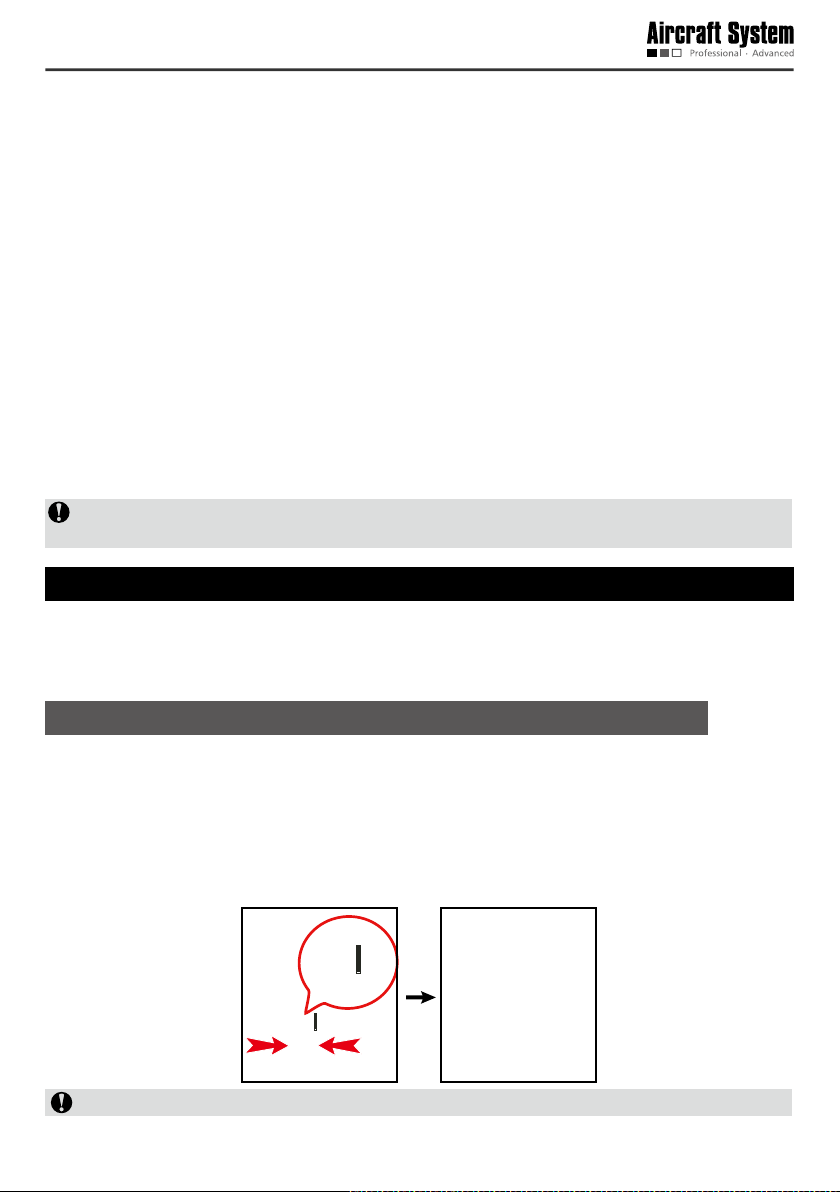
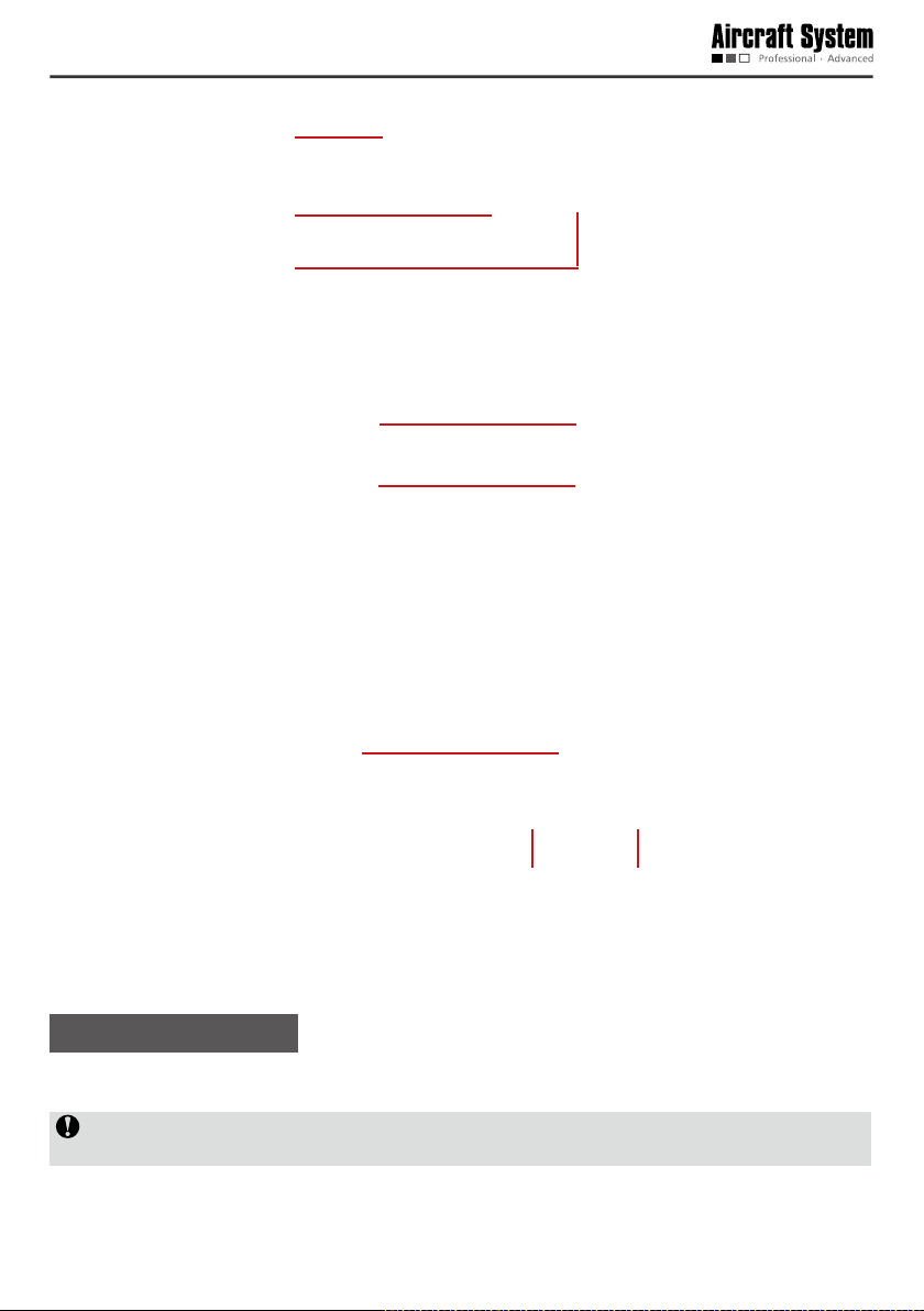
Connect the battery indicator to the battery in the direction shown below.
Black wire
to “–”
6
5
4
3
2
1
Notice: The black wire should be connected to “– ” during connection.
- 3 -
After connection, the battery indicator first displays the total voltage, and then displays the voltage
information of each battery cell in sequence: ALL (total voltage), No. 1, No. 2. No. 3, No. 4…
Precautions for Use of the Charger
1. During charging, do not put the battery near inammable matters.
2. Charging should be carried out in a dry and ventilated environment at room temperature.
3. Put the battery on a nonammable utensil, such as ceramic plate, for charging.
Specification of the Charger
Specication Parameter
AC input 100-240V (360-330W)
DC input 11-18Volt
Charging power 4×50W(200W)
Range of charging current 0.1-6.0A
Discharging power 4×5W(20W)
Range of discharging current 0.1-2.0A
Balanced discharging current of rechargeable battery pack 200mA/cell
Number of rechargeable lithium-ion cell 1-6 Cells
Net weight 1.73kg
Dimension 263mm×170mm×66mm
How to Use the Charger
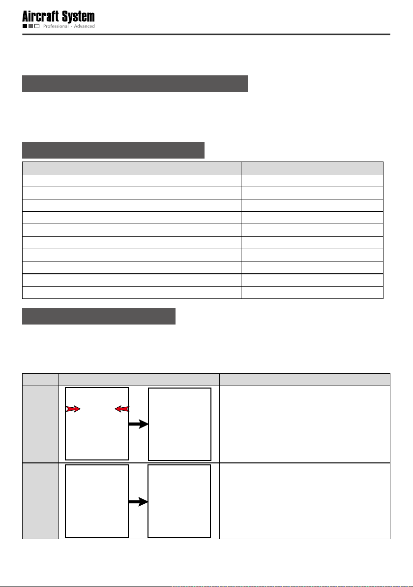
1 Take out the Battery
Please take out the battery before charging.
* Take out the battery of the aircraft:
Step Illustration Description
Hold the battery cover in the direction shown in
Step 1:
Step 2: Disconnect the power plug.
the gure; apply force according to the direction
of arrows to disengage the battery cover from
the body and then remove it.
- 4 -
Step 3:
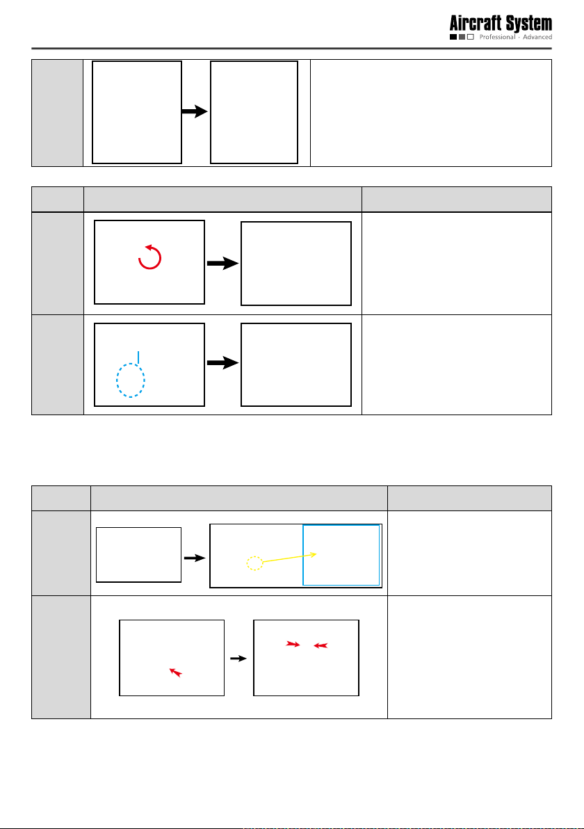
* Take out the battery of the remote control:
Step Illustration Description
Step 1:
Loosen the tie and take out the battery.
Rotate to open the battery cover
according to the direction of arrow
shown in the gure, and then remove
it.
Power plug
Step 2:
Disconnect the power plug and take
out the battery.
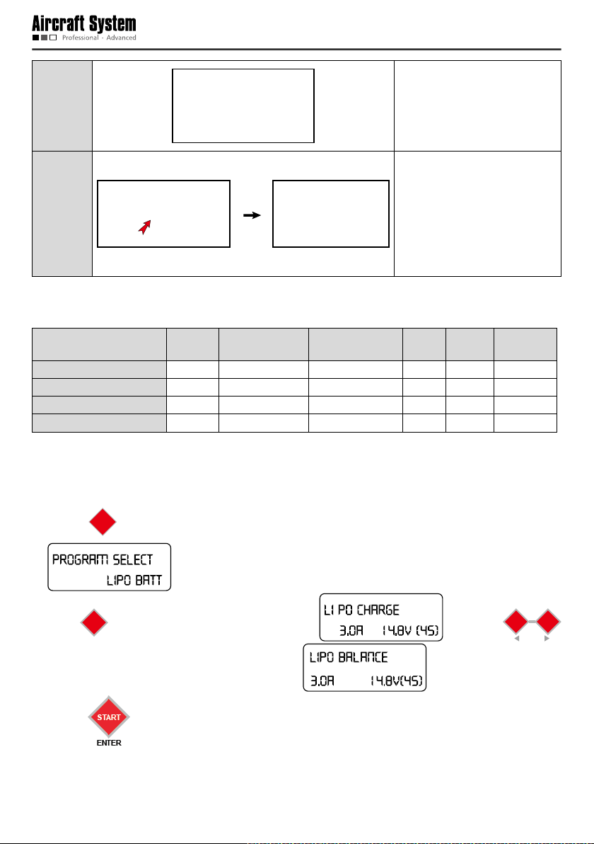
2 Connect the Battery to the Charger
* Connect the battery to the charger according to the steps shown below:
Step Illustration Description
Connect the two charger wires
Step 1:
Step 2:
according to the figure, and
pay attention to the polarity of
terminals.
Select the charging interface
corresponding to the number
of the cells (2S, 3S, 4S, 5S and
6S); connect the power plug
after connecting the charging
interface.
- 5 -
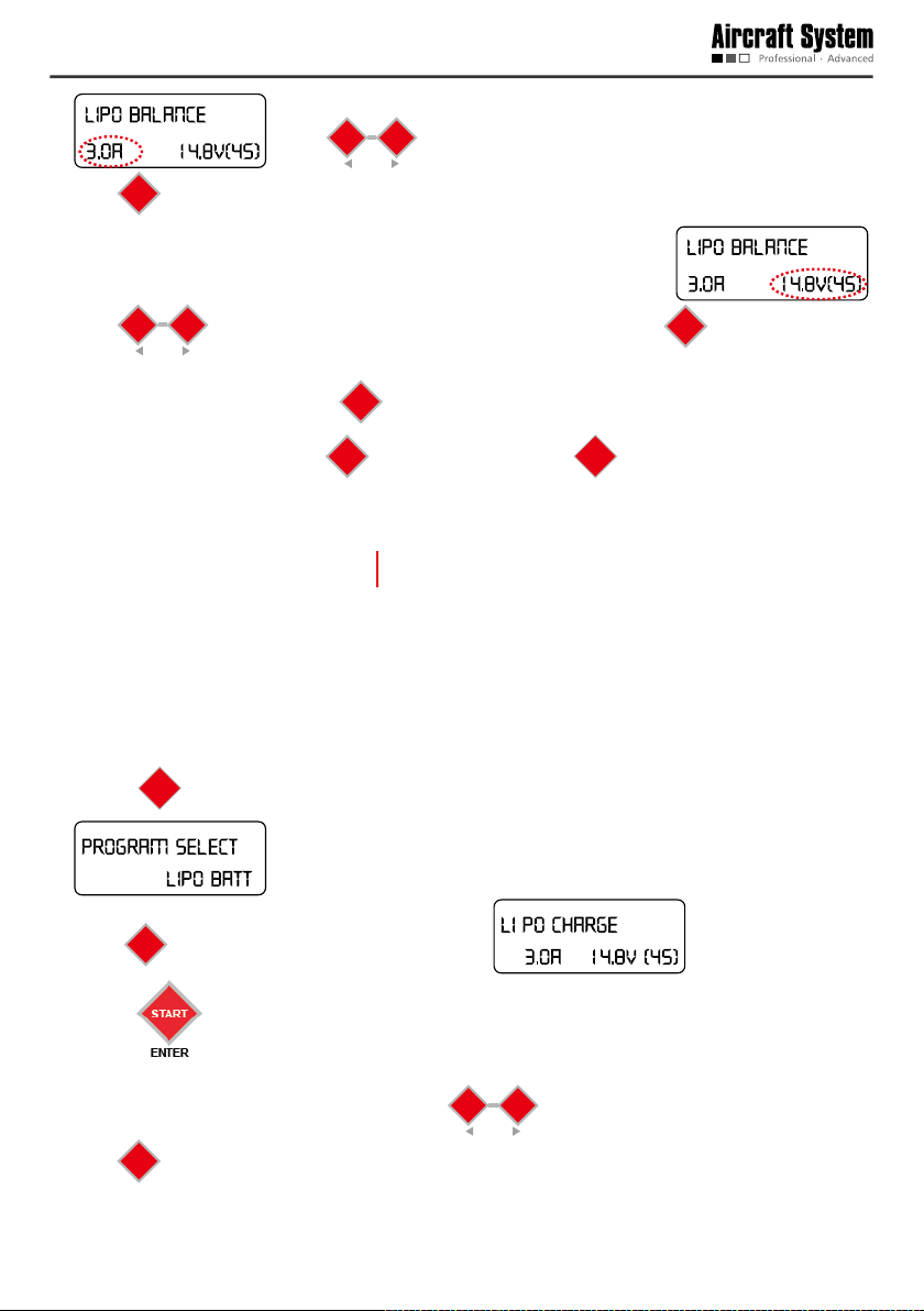
Step 3:
Complete connection.
Connect the charger to AC
220V power supply with the
Step 4:
supplied power cord; 4 LED
indicators of the charger will
be on and then you can set the
parameters of the charger.
3 Set Parameters and Start Charging
After the battery is connected to the charger, set the parameters for the charger as follows:
Battery
Battery
capacity
Battery of remote control 5000mAh 0-3A 2.0-3.0A 11.1V 3S CHARGE
Battery of aircraft 4000mAh 0-6A 3.0A 14.8V 4S BALANCE
Battery of aircraft 6000mAh 0-6A 3.5A 14.8V 4S BALANCE
Battery of aircraft 8000mAh 0-6A 4.0A 14.8V 4S BALANCE
Set the charger according to the above table; the detailed operation method is as follows:
Charging aircraft battery:
Range of current
regulation
Recommended
charging current
Voltage
Number
of cells
Charging
mode
BATT
1) Press
TYPE
to select a battery type, and call out LiPo BATT; the screen displays:
STOP
.
2) Press
for conrmation, and the screen displays: ; then press
START
ENTER
to select LiPo BALANCE, and the screen displays: .
3) Press
again for confirmation, and the current values begins to pulsate:
- 6 -
DEC
INC
STATUS
press
; press
START
for conrmation after the current is adjusted to the proper value.
ENTER
DEC
at this moment to decrease or increase the current value;
INC
STATUS
4) After confirmation of the current value, the voltage value begins to pulsate:
DEC
press
INC
to select the corresponding voltage of the battery; press
STATUS
START
for conrmation after
ENTER
the voltage is adjusted to the proper value.
START
5) After setting all parameters, hold
after successful detection, press
for 2 seconods, and the charger begins to detect the battery;
ENTER
START
to start charging, or press
ENTER
BATT
TYPE
to cancel charging.
STOP
6) After charging is completed, the charger sends out sounds, and the screen di splays the following
information:
Charging completed
Battery voltage after
charging is completed (V)
Charged capacity (mAh)
Charging the battery of remote control:
BATT
1) Press
TYPE
to select a battery type, and call out LiPo BATT; the screen displays:
STOP
.
;
2) Press
3) Press
press
for conrmation, and the screen displays: .
START
ENTER
again for confirmation, and the current values begins to pulsate:
; at this moment press
START
for conrmation after the current is adjusted to the proper value.
ENTER
DEC
to decrease or increase the current value;
INC
STATUS
- 7 -
4) After confirmation of the current value, the voltage value begins to pulsate: ;
DEC
press
INC
to select the corresponding voltage of the battery; press
STATUS
START
for conrmation after
ENTER
the voltage is adjusted to the proper value.
START
5) After setting all parameters, hold
after successful detection, press
for 2 seconods, and the charger begins to detect the battery;
ENTER
START
to start charging, or press
ENTER
BATT
TYPE
to cancel charging.
STOP
6) After charging is completed, the charger sends out sounds, and the screen di splays the following
information:
Charging completed
Battery voltage after
charging is completed (V)
Charged capacity (mAh)
To avoid short circuit resulted from misoperation, DO NOT pull out the charger wires during charging.
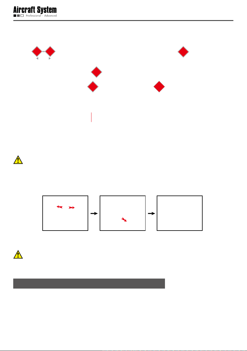
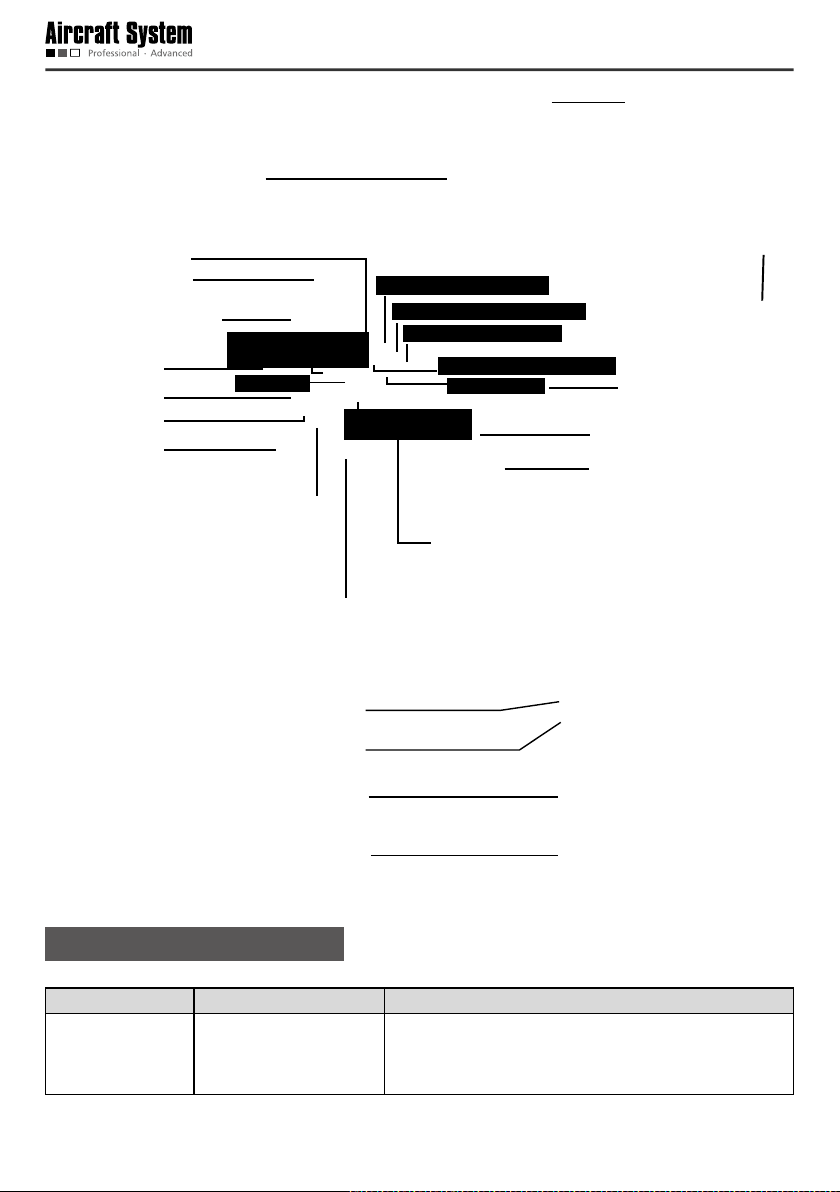
4 Complete Charging
After charging is completed, please disconnect the battery from the charger in the sequence shown
below:
First disconnect
the power plug
Then pull out the
charging interface
Finally pull out the
charger wires
To avoid short circuit caused by accidental contact between the positive and negative connectors,
which may further result in damage of the battery or other safety accidents, DO NOT pull out the
charger wires from the charger before the power plug is disconnected.
Precautions for Use of Lithium Battery
1. Do not disassemble or restructure the battery;
2. Do not short-circuit the battery;
3. Do not use the battery near heat sources;
4. Do not drop the battery in water or get it wet;
- 8 -
5. Do not charge the battery near re or in the sun;
6. Do not impact or drop the battery;
7. Do not use the battery when it is severely damaged or deformed;
8. Do not charge the battery in reverse polarity or over-discharge it (Reverse charge or over-discharge
can cause the battery drum kits, leakage, batteries breakdown, or explosion, etc.) ;
9. Do not connect the battery in reverse polarity;
10.Any waste battery should be recycled in an environment-friendly way;
11.If the battery will be idle for a long time, the battery should be taken out and charged once every six
months to 3.90±0.05V for storage, so as to maintain the battery performance and prolong its service
life.
List of Components
The following components are included in the package of this product. Please check carefully at the time
of purchase. In case of any missing component or damage, please feel free to contact us.
Main unit of aircraft: 2 sets Main unit of remote
control: 1 set
Main unit of ground
control station: 1 set
Charger: 1 set (including
power cable, charger
connecting wires,
vehicle-mounted
charger clamp.)
Aircraft battery: 8000mAh
&6000mAh &4000mAh
2pcs each
Propeller (4pcs/set): 4 sets Propeller holder (4pcs/
Professional protection
box for aircraft: 2pcs
set): 4 sets
- 9 -
Battery indicator: 1pc Battery of remote
Undercarriage (2pcs/
set): 4 sets
control: 1pc (5000mAh)
Sunshade: 1pc
Remote control strap: 1pc
`
Video antenna: 2pcs
Radio antenna: 2pcs AV output cable
of remote control
(optional): 1pc
USB data cable (8-pin) of
camera: 2pcs
High-gain dual-band directional
antenna: 1pc (including 2
feedback lines and 1 tripod)
CD-ROM: 1pc Instruction Manual: 1
Notice: The accessories of actual products may vary slightly, and the above gures are for reference
only.
USB data cable (5-pin)
of remote control: 1pc
Vehicle-mounted
charger clamp cable
for ground station
(optional): 1pc
copy
Wrench: 1pc Adaptor of ground
AV output cable
for ground station
(optional): 1pc
control station: 1pc
Accessory box: 1pc
Aircraft
* The ight of the aircraft can be controlled through the remote control or the ground station; there are
several ight modes available such as manual remote control, spot hover and route ight.
* The aircraft system integrates flight control software, data radio, image radio, control joystick and
mission control buttons; thus, ight data and real-time images can be viewed conveniently during the
ight, and real-time control of air route and mission of the aircraft can be realized.
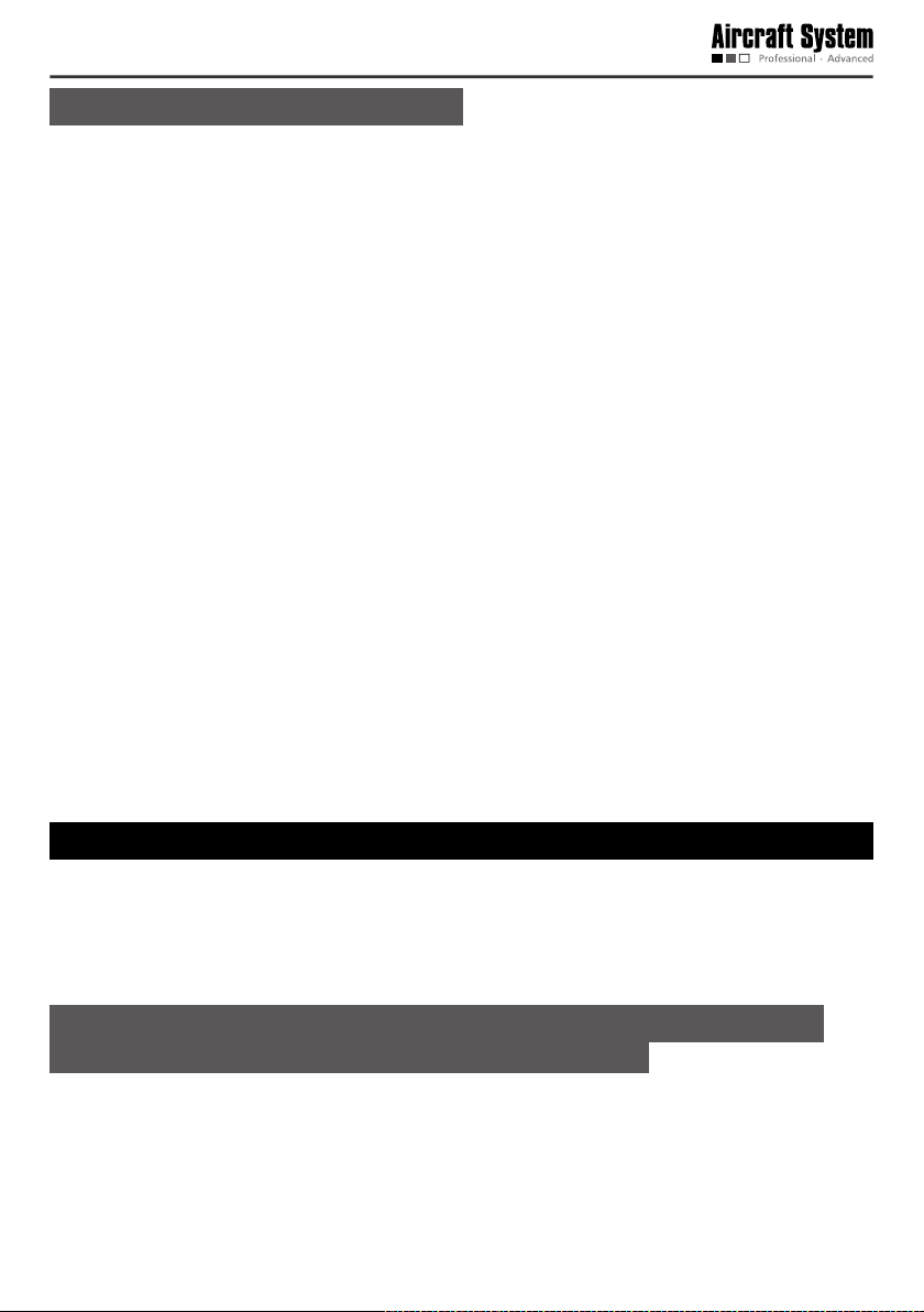
Guide for Components of the Aircraft
- 10 -
ON OFF
Propeller
Undercarriage
Airborne camera
A propeller with "P" should be installed on a support arm with "P".
USB port
Battery cover
Power switch of aircraft
Radio antennaVideo antenna
Install Propellers
There are two clockwise propellers and two counter-clockwise propellers. The letter “P” on a propeller
indicates it is a counter-clockwise propeller which should be installed on a support arm with “P”.
Wrong installation of clockwise and counter-clockwise propellers will inevitably result in errors in the
aircraft lift system, further leading to unpredictable consequences.
Place the propeller blades and propeller holders on corresponding motor shafts; use the wrench
- 11 -
( ) to clockwise tighten the propeller holders ( ).
A propeller with “P” should be installed on a
support arm with “P”.
Install Battery
1. First remove the protective cover at the bottom of the aircraft: squeeze the two sides of the cover to
remove the protective cover.
2. Take the battery out of the packing box, install it in the battery case at the bottom of the aircraft, and
tighten it with a xing strap.
3. After it is conrmed that the battery has been properly installed, connect it to the power interface to
power up, install the protective cover.
Notice: Please make sure the power switch of the aircraft is in the OFF state during installation of
the battery.
4. After completion of the above three steps, place the aircraft on the ground (a flat surface is
recommended); then turn ON the power switch of the aircraft.
Notice: The aircraft will carry out self-checking for 3-5seconds after it is powered up; at this
moment, please do not move the aircraft or operate the remote control (before self-checking,
please make sure that the power switch at the aircraft tail is in the ON state); after self-checking is
completed, if the course indication of the remote control coincides with the orientation of the aircraft
nose, it indicates the self-checking is passed.
- 12 -
Preparations before Take-off
1. Remove the lens cap of the airborne camera.
2. Check the batteries of the aircraft and the remote control to see if the battery level is high enough (the
recommended voltage for the aircraft is above 16V, and the remote control above 12V); in case of low
battery level, please replace the battery.
3. Check the propellers of the aircraft to see if they are tightened.
4. Make sure that the manual/automatic ight switch of the remote control is in the manual ight mode.
5. Check the servo; in case of any anomaly (indication bars do not jump or indication is inaccurate during
checking), please calibrate the joystick. (For servo checking and joystick calibration, please make sure
the power switch of the aircraft is in the OFF state, in order to avoid accidental take-off of the aircraft.)
6. Turn off the power switch after the aircraft is placed at the take-off position; to ensure safety, there
should be no obstacle within the radius of 5-10m around the take-off position.
7. Turn on the power switch of the aircraft; for outdoor ight, GPS satellite positioning is required; take-off
is allowed only when the GPS signal strength indicator is greater than or equal to 6.
8. Before take-off, please make sure that only one aircraft is started; to avoid accidents, it is forbidden to
simultaneously start two aircrafts.
9. Before take-off, please make sure that the video and radio antennas have been properly installed to
avoid inuence on the ight and the video receiving distance or damage to the transmitter modules
inside the aircraft and the remote control.
10.When the remote control is used to control the aircraft, please make sure that the option of “Send
joystick data” in the ground station software is not checked before take-off; when the ground station
joystick is used to control the aircraft, please make sure that the remote control is in the OFF state
before take-off.
Control the Flight with the Remote Control
The remote control is specially developed for AEE unmanned aircraft system to make it convenient for
controlling the ight of the unmanned aircraft. The remote control can independently control the ight of
the aircraft, and can simultaneously display the ight status of the aircraft and the real-time images from
the airborne camera.
Guide for Components of the Remote Control
and Description of Their Functions
- 13 -
LCD display (touch screen)
Local recording button
Menu/return button
Throttle (up, down) / course
adjustment button
Zoom out button
Airborne recording
(left, right) joystick
Course ne
stop button
Power switch
Local recording indicator
Airborne recording indicator
Throttle ne
adjustment button
Strap hole
Pitch ne
adjustment button
Zoom in button
Roll ne adjustment button
Radio antenna
Power switch indicator
Airborne recording button
Shutter button
Pitch (up, down) / roll (left,
right) joystick
Video antenna
USB port
Manual/automatic ight switch
PTZ control button
AV signal output interface
Support frame of remote control
Battery cover lock
Battery cover
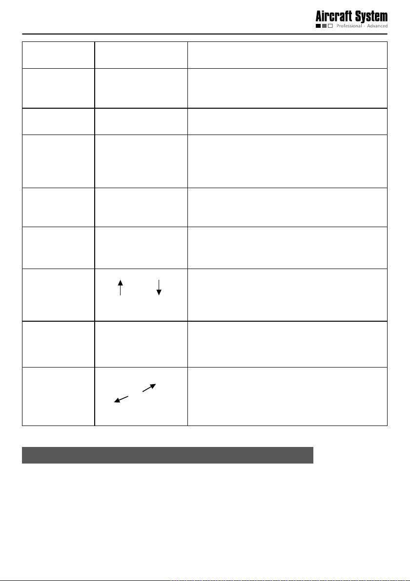
Description of Buttons
Name of button Illustration Description of function
Local recording on
remote control
The remote control saves the video recording sent back
by the aircraft to local memory. Press it to start recording,
press it again to stop recording.
- 14 -
Airborne camera
video recording
Shutter
Stop recording
Menu
The airborne camera begins recording when it is pressed
once.
Press it to take a photo (during recording of the airborne
device, the snapshot function is available in three
resolution modes: 1080p/25f, 960p/25f and 720p/25f).
The airborne camera stops recording when it is pressed
once.
Press “M” to enter the main menu of remote control.
Long press “M” for 5 seconds to send the command to
go home immediately; the aircraft will enter the go-home
mode after receiving the command.
Zoom “+”
Zoom “-”
Manual/automatic
ight switch
Power switch
PTZ control knob
Turn upwards Turn downwards
Lens upwards
Lens downwards
Zoom control of camera: zoom in.
Zoom control of camera: zoom out.
Turn upwards: Manual ight mode.
Turn downwards: Automatic ight mode (GPS mode).
Slide leftwards to turn it ON; slide it rightwards to turn it
OFF.
The angle of the camera can be adjusted by turning this
knob.
Preparations for the Remote Control
* Installation of Antennas
- 15 -

Radio antenna (longer)
Video antenna (shorter)
“Video” is indicated here
“Radio” is indicated here
Video Radio
Install the antennas shown below in the corresponding positions of the remote control and clockwise
tighten them.
Radio antenna corresponds to: Radio
Video antenna corresponds to: Video
Notice: Please make sure that the video and radio antennas have been properly installed to avoid
inuence on the ight and video receiving distance or damage to the transmitter modules.
* Installation of Sunshade
The installation method is shown as follows:
* Screen on Power-on:
- 16 -

Indication of
battery level
of aircraft
Indication of
GPS signal
strength
Indication of
speed value
Longitude
and latitude
of take-off
position
Throttle ne
adjustment
Indication of airborne
recording status
1080P/25
Heading Indicator
Indication of local recording
status of remote control
Indication of battery
level of remote control
Horizon instrument
(indication of roll and
pitch attitudes)
Indication of altitude
Longitude and latitude
of current position
Pitch ne adjustment
Course ne adjustment
Airborne camera
resolution
Indication of
camera clock
Indication of free
memory space of
airborne camera
Roll ne adjustment
Set Parameters on the Screen of the Remote Control
Press “M” to enter the interface of “Function Setting” of the remote control:
* Servo Checking
Check if the functions of joystick, flight mode switch and PTZ control knob on the remote control are
normal through “Servo Checking”.
Notice: Servo checking should be carried out before take-off.
Here are the steps for servo checking:
1. Press “M” to enter the interface of “Function Setting” of the remote control.
2. Touch “Servo Checking” to enter the setting interface:
3. At this moment, turn the left and right joysticks by the maximum angle possible, toggle the ight mode
- 17 -

switch and rotate the PTZ control knob, and the relevant indication bars will pulsate correspondingly;
the functions of roll, pitch, throttle, course, automatic ight switch and angle adjustment of airborne
camera can be checked.
Notice: During servo checking, please make sure that the aircraft power switch is in the OFF
state, in order to avoid accidental startup of the aircraft.
* Joystick Calibration
Touch “[Start]” for joystick calibration in the interface of “Servo Checking” in the above step; turn the
left and right joysticks for 5-10 circles by 360° to enter the state of joystick calibration; indication bars
of roll, pitch, throttle and course will pulsate correspondingly; click “DONE” to finish the calibration
process. Carry out servo checking after completion of calibration; it is OK if servo checking shows
normal result; otherwise, recalibration is required.
Notice: During joystick calibration, please make sure that the aircraft power switch is in the OFF
state, in order to avoid accidental startup of the aircraft.
* Camera Setting
Touch “ ” to enter the interface of “Airborne Camera Setting” shown below: Video Recording
Settings
, Photo Shooting Settings , and Local Settings of Airborne Camera )
Video Recording Settings
1) Setting Image Resolution
- 18 -

PAL-system
• Zooming is not supported in the mode of 848x480P 100f.
• Time indication is not supported in the mode of 1080I/50f.
1920 × 1080i
50f 16:9
1920 × 1080P
25f 16:9
1280 × 960P
25f 4:3
1280 × 720P
50f 16:9
1280 × 720P
25f 16:9
848 × 480P
100f 16:9
2) Selection of Visual Angle
This device provides 3 options on visual angle (Wide visual angle “ ” / Moderate visual angle “ ” /
Narrow visual angle “
preview mode:
The above optional visual angles can be selected according to your preference and needs.
Notice: The selection of visual angle is supported only under the resolution mode of 1080P or 1080i.
”); the following is an example of an image under different visual angles in the
Wide visual angle
Moderate visual angle
Narrow visual angle
Same scenery photographed at different angles
3.) Setting Bit Rate
This device provides two options: High bit rate “ ” and Normal “ ” (when high bit rate is selected,
the image quality will be higher, but the le size will be enlarged).
- 19 -

Photo Shooting Settings
1)Image resolution of photo shooting
3.0M (2048×1536 4:3)
5.0M (2592×1944 4:3)
8.0M (3200×2400 4:3)
2)Selection of Shooting Mode:
Single shooting: In the one shooting mode, the system will take one photo when “Shutter” is pressed
once.
Continuous shooting (three): In this mode, the system will take three photos continuously when “Shutter”
is pressed once.
3) Automatic continuous shooting mode
The time interval of automatic continuous shooting can be set as “OFF”, “1S”, “3S”, “5S” and “20s”.
When “Shutter” is pressed, the system will take one photo at each time interval until “Shutter” is
pressed again to cancel continuous shooting.
- 20 -

Notice: The continuous shooting (three) mode and the automatic continuous shooting mode
cannot be enabled simultaneously.
Local Settings of Airborne Camera
Touch to enter the interface of “Local Settings of Airborne Camera”:
1) Loop Recording: ON, OFF
When “Loop Recording” is ON, recording is saved as a segment le by each 10 min; if the space of the
memory card is not enough, the rst recording le will be overwritten automatically.
Notice: During airborne recording, the function of loop recording is valid only when the free
memory space of the camera is more than 200M.
2)Light Metering Mode
Average metering: use this mode when the luminance difference between the photograph subject and
the background is relatively slight and steady.
Central area metering: It is the default mode, applying to scenes when there is certain luminance
difference between the photograph background and the subject or the photograph subject relatively
accords with the background.
Central spot metering: It applies to small-sized subject under extremely bright or dark background.
- 21 -

3) Formatting
The airborne camera can be formatted to remove all les in it. Make sure you do not need the data
before formatting!
Yes
4) Restore Factory Settings
This operation will restore all settings of this device to the factory settings.
Yes
5) Date Setting
a. Touch “Date Setting” to enter the setting interface of “Time Indication on Image”:
b. Touch “ ” or “ ” corresponding to settings of “Year, Month, Day, Hour, and Minute”, to complete
the settings of Year, Month, Day, Hour, and Minute.
c. Touch “Save” to complete setting.
Notice: When “Time Indication on Image” is ON, after “Save” is pressed to complete setting, date
and time will be indicated at the bottom right corner of the video and photo; when “Time Indication on
Image” is OFF, there will be no such indication. In the resolution mode of 1080I/50, date and time will
not be indicated in the video and photo.
* Language Selection
- 22 -

1. Press “M” to enter the interface of “Function Setting” of the remote control.
2. Touch “Language Selection”.
· Language options: English
3. After selecting the desired language, touch “Save” to complete setting.
* Information of Software Version
Start up the Aircraft
* Start the Aircraft
Notice: During outdoor ight, please make sure that the gure of GPS signal strength indicator is
greater than or equal to 6.
Start the aircraft in the following way:
Simultaneously turn the left and right joysticks to the directions shown below
Turn the left joystick to the bottom left corner Turn the right joystick to the bottom right corner
Immediately loosen the joysticks when the propellers begin to rotate, and the aircraft enters the startup
state; turn the left joystick upwards, and the aircraft begins to climb upwards.
- 23 -

Direction Control
Directions of the aircraft are dened in the following gure:
Front
(aircraft nose)
See the following table for details:
Joystick Attitude of aircraft Illustration
Turn the left joystick forwards,
and keep the right joystick in the
original position.
Turn the left joystick backwards,
and keep the right joystick in the
original position.
Left
Rear
Climb Upwards
The motor speed and the
propeller speed increase.
The climbing speed
increases with the joystick
amplitude increases.
Go downwards
The motor speed and
the propeller speed
decrease.
The descending speed
increases with the joystick
amplitude increases.
Right
Rise
Horizon
Horizon
Descend
- 24 -

Turn the left joystick rightwards,
and keep the right joystick in the
original position.
Turn the left joystick leftwards,
and keep the right joystick in the
original position.
Turn the right joystick forwards,
and keep the left joystick in the
original position.
Turn the right joystick
backwards, and keep the left
joystick in the original position.
Rotate the nose
rightwards (rotate
clockwise)
Rotate the nose leftwards
(rotate counter-clockwise)
Fly forwards
The nose tilts downwards;
the aircraft inclines
forwards and flies along
the nose direction. At this
moment, it is needed to
slightly push forward the
throttle to adjust the ight
altitude so as to realize
horizontal flight of the
aircraft.
Fly backwards
The tail tilts downwards;
the aircraft inclines
backwards and ies along
the tail direction. At this
moment, it is needed to
slightly push forward the
throttle to adjust the ight
altitude so as to realize
horizontal flight of the
aircraft.
Horizon
Fly backwards
(tail direction)
Horizon
Rotate the
nose clockwise
Rotate the nose
counter-clockwise
Fly forwards
(nose direction)
R
ight view
R
ight view
Pitch angle
Pitch angle
- 25 -

Fly rightwards
The aircraft inclines
rightwards
At this moment, it is
Turn the right joystick
rightwards, and keep the left
joystick in the original position.
Turn the right joystick leftwards,
and keep the left joystick in the
original position.
The throttle lever of the remote control controls the propeller speed; it can control the rising
and descending of the aircraft. The throttle lever should be pushed gently, and fast change should
be avoided. The right joystick of the remote control is the direction lever; the aircraft go leftwards,
rightwards, forwards and backwards respectively when the right joystick is pushed leftwards,
rightwards, forwards and backwards.
During manual ight, the forward motion direction of the aircraft can be corrected by combing the
right joystick while operating the left joystick. When the aircraft is in the air, any unpredictable airow
change will cause drifting and autorotation of the aircraft, which breaks the original balance.
needed to slightly push
forward the throttle to
adjust the flight altitude
so as to realize horizontal
ight of the aircraft.
Fly leftwards
The aircraft inclines
leftwards
At this moment, it is
needed to slightly push
forward the throttle to
adjust the flight altitude
so as to realize horizontal
ight of the aircraft.
Horizon
Aircraft tail
Row leftwards
Horizon
Aircraft tail
ON O FF
ON OFF
ON OFF
Row rightwards
Roll angle
Roll angle
Go Home and Shut down the Aircraft
* One-key Go Hone
When the GPS signal strength indicator is greater than or equal to 6 during outdoor ight, long press the
“M” button for 5s to send the command requiring the aircraft to go home immediately; after receiving the
command, the aircraft will enter the go-home mode to return and land at the take-off position.
Notice: In the manual flight mode, 10s after the aircraft receives and executes the go-home
command, you can turn the automatic/manual ight switch downwards and then upwards once to go to
the manual ight control mode. During landing of the aircraft, please make sure that there is no movable
obstacle or person within 5-10m around the landing position.
* Shut down the Aircraft
Shut down the aircraft in the following way:
- 26 -

Turn the left joystick to the bottom left corner
Notice: During ying of the aircraft, the above startup and shutdown operations are forbidden; or else,
unpredictable consequences may be resulted in. When operation is completed, please timely turn off the
power switch of the aircraft and take out the battery to avoid continuous consumption of the battery.
Turn the right joystick to the bottom right corner
Control the Flight with the Ground Station
The ground control station (hereinafter referred to as the “ground station”) is one of the ground control
devices for AEE unmanned aircraft system. Compatible with the main functions of the hand-held remote
control, it allows you to easily edit waypoints on a 3D map, set air routes, view real-time information
such as coordinates, ight attitude, speed and video sent back by the aircraft. With a built-in professional
industrial computer, multi-mission processing can be realized. The aircraft can y autonomously along the
air route preset in the ground station software, and real-time videos and other information sent back by
the aircraft can be received and saved.
Functions and Features of the Ground Station
* With the waypoint editing function, at most 100 waypoints can be added.
* Check the aircraft status in a real-time way, including such information as battery level, speed, altitude,
longitude and latitude.
* Automatic control of take-off and landing.
* With the joystick control function, manual ight can be realized.
* Air routes can be set, enabling the aircraft to y autonomously.
* With the built-in high-capacity battery, it can satisfy the requirement of long-time outdoor use.
* With the powerful information processing function, it can simultaneously display satellite maps and
real-time videos of the aircraft.
* It has the reliable multi-level protection function.
* It can control the working status of the airborne camera.
* It can set the airborne camera.
* It is equipped with professional protection box.
Panel Layout and Interface Functions of the
Ground Station
- 27 -

No. Name Function description
It is used to support the screen panel when the ground station panel
1 Support rod
2 Main power indicator It will be on when the main power switch is turned on.
3 Charge indicator
External DC power
4
5 Main power switch Turn on/off the main power.
6 Start Main Unit Button Turn on/off the operating system of the ground station.
7 Cooling fan It is used for heat dissipation of the ground station.
8 Left joystick
9 Right joystick
10 Network interface Connect to external network
11 USB Connect to external USB device
12 Wiring sealing plug Protect the connecting wires.
13 Auto/manual y switch Switch between manual y and auto y
14 Radio antenna interface
15 Video antenna interface Receive real-time video signals of the aircraft
16
interface
Airborne video recording
button
is open; it can be taken in when the panel is closed; use a screw to x
it.
It is red during battery charging and green when the battery is fully
charged.
Connect to an external power adapter to supply power to the system
or charge the battery.
It is used for manual control of aircraft ight, including two channels,
namely, yaw and throttle.
It is used for manual control of aircraft ight, including two channels,
namely, roll and pitch.
Transmit ight commands; receive ight attitude, sensor information,
longitude and latitude, etc.
Press the airborne camera once to start recording
- 28 -

Airborne photo shooting
17
Stop airborne recording
18
19 Keyboard and mouse Carry out relevant operations of the industrial computer
20 Zoom “-” Zoom control of camera: zoom out
21 Zoom “+” Zoom control of camera: zoom in
22 AV interface
23 Reserved button Reserved button (no function)
button
button
Press the airborne camera once to start photo shooting
Press the airborne camera once to stop recording
The airborne camera on the aircraft sends back video output in a realtime way
Preparations for the Ground Control Station
* Open and Fix the Top Cover
Open the top cover of the ground control station and use the support rod to x it:
* Installation of Antennas
Differentiation of antennas:
Radio antenna Video antenna
Metal antenna
“Radio” is indicated here
Connect the data communication antenna on the left side, and connect the video communication antenna
High-gain dual-band
directional antenna
Metal antenna
“Video” is indicated here
High-gain dual-band
directional antenna
- 29 -

on the right side; clockwise rotate and fix the antennas after they are aligned with the corresponding
⬉ৄ㒓
5DGLR
interface:
Radio antenna
For short-distance operation, it is suggested the metal antenna should be used; for long-distance
control, it is suggested the high-gain dual-band directional antenna should be used.
Video antenna
㾚乥㒓
9LGHR
* Connect Power Adapter
Before use, please rst check if the battery level of the ground control station is high enough. In case
of low battery level, please use the power adapter to charge the ground station:
Connect the power
⬉⑤䗖䜡఼䖲
adapter to the external
Ⳉ⌕⬉⑤ষ
DC power supply
* Startup
First turn on the main power switch, and then press the “Start Main Unit” Button to start the ground
control station.
ᠧᓔ⬉⑤ᘏᓔ݇
1. Turn on the main power switch
2. Press the “Start Main Unit ” Button
ᣝϟĀЏᴎࡼᣝ䬂ā
Notice: The default system is Microsoft Windows XP Professional (on/dev/sdal).
- 30 -

Introduction to Main Interfaces of the Ground Station
Software
After startup, double-click the icon of the ground station software to open the ground station
software. The main interface of the software is as follows:
1
2 3 4 5
7
9
1. “File” Menu
• LoadMission:Load local-stored ight missions.
• SaveMission:Save the currently edited ight mission.
2. “View” Menu
Click the “View” pull-down menu to make settings corresponding to the content displayed in the
interface:
• Toolbar: Show or hide the toolbar.
• InstrumentsDisplayBar:Show or hide the instruments display bar.
• MissionEditor:Show or hide the mission editor.
• StatusBar:Show or hide the status bar.
• FullScreen:Display a map in full screen, or exit from the full screen mode.
3. “Tool” Menu
• JoystickData: Ground station connects to joystick serial ports.
4. “Settings” Menu
• LanguageSetting: Chinese, English
• VideoStoreSetting: Storage paths of videos and screenshots can be selected.
5. “Help” Menu
6. Toolbar
8
11
6
10
- 31 -

Connect or close serial ports, load mission, save mission, display track, etc.
7. Video Management Window
(Please see the section of “Functions of Video Management Window in Ground Station Software” for
details.)
8. Navigation Map
Display real-time maps.
9. Navigation Bar
Zoom in, zoom out, change or move map locations.
10.Flight Mission Editor
• Click “Edit Waypoint” to reedit the
mission that has been edited.
• Click “Finish Editing” to confirm the
current mission; the color of air route
Green indicates
the current
status of the
mission.
Waypoint list;
the color of a
waypoint icon
changes to
green when
it is clicked,
indicating this
waypoint is
selected.
Attributes of
the waypoint
selected can
be edited:
longitude,
latitude, altitude,
speed, and hold
time.
Historical
information of
system action
is displayed
here. To clear
historical
information,
please click
“Clear All”.
changes to green.
• To add a waypoint, click “Add Waypoint”,
and double-click the position where you
want to add the waypoint on the map to
add the new waypoint.
• Select the waypoint (green) you want
to delete and click “Delete Waypoint” to
delete this waypoint.
• Click “Upload Mission” to upload the
current ight mission to the aircraft.
• Click “Download Mission” to verify if the
mission is successfully uploaded.
• To delete the mission currently being
edited or to open a new mission, click
“Clear Mission”.
• Click “Edit Waypoint” to reedit the
mission that has been edited.
• Click “Finish Editing” to confirm the
current mission; the color of air route
changes to green.
• To add a waypoint, click “Add Waypoint”,
and double-click the position where you
want to add the waypoint on the map to
add the new waypoint.
• Select the waypoint (green) you want
to delete and click “Delete Waypoint” to
delete this waypoint.
• Click “Upload Mission” to upload the
current ight mission to the aircraft.
• Click “Download Mission” to verify if the
mission is successfully uploaded.
To delete the mission currently being
edited or to open a new mission, click
“Clear Mission”.
- 32 -

Instruments Display Bar
Altitude indicator Airspeed indicator Attitude indicator Heading indicator
Status Bar
Display such information as longitude and latitude of the aircraft, number of GPS satellite, and battery
level in a real-time way; search, name and locate map data.
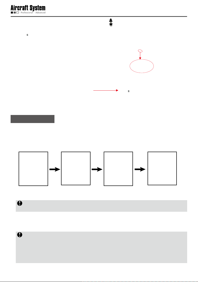
Execute Manual Fly Missions with the Ground Station
Flight missions can also be executed through manual operations with the ground station. The steps are
as follows:
Start the ground station software
Switch to the “Manual Fly” mode
Power up the aircraft to receive satellite signals
Connect serial ports and send joystick data
Check before take-off
Start up the aircraft
Perform manual take-off
Control aircraft ight with joysticks
Shutdown the aircraft
Complete the ight mission
For joystick control methods during manual y, please see the instructions for manual y with the remote
- 33 -

control.
Execute Auto Fly Missions with the Ground Station
An auto fly mission can be executed according to the following steps:
Start the ground station GS software
Switch to the “Auto Fly” mode
Connect serial port and send joystick data
Power up the aircraft to receive satellite signals
Edit the ight mission
Complete mission editing
Upload the ight mission to the aircraft
Download the ight mission for verication
Start up the aircraft
Perform auto take-off or manual take-off
Perform “Auto Fly” or “Fly To” to a designated
waypoint
Go home / abort mission and go home
Shutdown the aircraft
Complete the ight mission
You can continue to edit a completed
mission, and then click “Finish Editing”.
The waypoint can be edited midway for
continued ight
Execute One-button Auto Fly Missions with the Ground
- 34 -

Station
One-button Auto Fly
An
Start the ground station GS software
Switch to the “Auto Fly” mode
Connect serial port and send joystick data
Power up the aircraft to receive satellite signals
mission can be executed according to the following steps:
Edit the ight mission
Complete mission editing
Upload the ight mission to the aircraft
Download the ight mission for verication
Make sure the throttle at minimum
the “One-button Auto Fly” button
Press
Make sure the throttle at minimum
Then switch to the “Manual Fly” mode
Shutdown the aircraft
Complete the ight mission
You can continue to edit a completed
mission, and then click “Finish Editing”.
1 Start the Ground Station GS Software (Hereinafter
Referred to as the “Ground Station Software”), and
Select the Map Type.
Please make sure maps have been downloaded before starting the ground station software. Double-click
to open the ground station software, and the system will ask you to select a map type. Select the desired
- 35 -

map type and click “OK”, and maps will be loaded automatically.
If maps cannot be loaded normally after the ground station software is opened, please restart the
software, connect to the network and try loading again.
2 Connect Serial Ports
Connect serial port COM1 (ground station connects to the communication serial port)
Find [COM1 Connect] on the toolbar; please select serial port COM1, and click “Connect”. A dialog
box showing “Serial port opened” will pop up on the screen.
Connect serial port COM2 (ground station connects to the joystick serial port)
The dialog box of “Joystick Data” (as shown below) will pop up through Menu
Data. Select serial port COM2 and click “Connect” to connect the joysticks which are used to control
the aircraft.
Check “Send joystick data”; the progress bars will have corresponding indications when the joysticks
are turned..
Tool Joystick
Serial port COM2 is used to receive data from joysticks connected to PC and then send the data to the
aircraft via serial port COM1. Therefore, before connection of serial port COM2, please conrm that
serial port COM1 has been connected.
In case of any error in connection of serial ports, click “Close” on the toolbar and carry out
reconnection.
Calibration
- 36 -

After connecting serial port COM2, calibrate the joysticks according to the following steps. The
calibration function is mainly used to adjust the maximum, minimal and median values of the joysticks.
Click “Calibration”.
Rotate the left and right joysticks by 360° until the progress bars of 4 channels pulsate.
Push the left and right joysticks, and observe whether there is corresponding pulsation on the progress
bar of each channel.
If the calibration is inaccurate, please repeat the above steps.
Important notice:
1. After successful connection of serial port COM2, the aircraft can be manually controlled with the
ground station joysticks after the manual y mode is switched to.
2. When the remote control is used to control the aircraft, please make sure that the option of “Send
joystick data” in the ground station software is not checked before take-off; when the ground station
joysticks are used to control the aircraft, please make sure that the remote control is in the OFF state
before take-off.
3. For joystick calibration, please uncheck “Send joystick data”, to avoid unpredictable consequences
caused by accidental take-off of the aircraft.
3 Power up the Aircraft to Receive Satellite Signals
After the aircraft is powered up, you can view the information received from the aircraft on the status
bar of the ground station software, such as voltage, attitude, altitude, and number of GPS satellites.
The ight mission can be edited only when the number of GPS satellites is no less than 6.
4 Edit Flight Mission
Positioning
Method 1: Add the map location information to the list according to the following steps:
Click “Search” to load the mapInput place name
After successful adding, you can select an added address from the list; the map will automatically locate
to this address after the “Positioning” button is pressed.
Method 2: When the number of GPS satellite is no less than 6, you can directly click “Display Track”; at
- 37 -
Click “Add” to save the map data of the
current view and add them to the list

this moment, the map will locate to the current position of the aircraft.
After the ground station software is started, the default position displayed on the map is the last added
position.
As to undesired positioning information, you can also delete it by clicking “Delete” after selecting the
location name.
The ground station software has the ofine positioning function.
Notice:
1. Maps of Google Satellite and Google Earth for the same area are not universal; please add maps
separately.
2. To use the ofine positioning function, please download and back up maps in advance.
Add Waypoint
Method 1: Add a waypoint, please directly double-click the position where you want to add a waypoint on
the map.
Method 2: Click [Add Waypoint] in the Flight Mission Editor, and then click the position where you want to
add a waypoint on the map to add a waypoint.
It is better to add the first waypoint near home point to prevent the aircraft from colliding with
obstacles due to excessive obliquity of the aircraft route during its ascending.
Add all the desired waypoints with the same method.
After adding the waypoints, you can view the following information of waypoints on the map:
Horizontal projection distance between two waypoints
Air route
Index number of waypoint
Color of air route before editing is nished:
Red: Abnormal
White: Normal
Hidden air route: Abnormal
Notice: Only Google Earth hints abnormality in air route altitude; Google Satellite does not have such
hint, so the air route altitude should be judged by yourself.
Edit Waypoint
After adding a new waypoint, you can continue to edit the waypoint.
- 38 -

Notice: After selection, the color of waypoint icon changes to green , indicating this waypoint is
selected and can be edited.
Change waypoint position:
Method 1: Use the left mouse button to drag the waypoint to the desired position.
Method 2: Edit longitude and latitude in the Flight Mission Editor. Input the desired longitude and
latitude in the corresponding attribute values, then the waypoint will automatically move to the
corresponding position.
Change altitude, speed and hold time of waypoint
Input the desired gures in the corresponding attribute values to change the altitude, speed and hold
time of the waypoint.
Notice: To edit the position and altitude of a waypoint, please make sure altitudes of all waypoints are
applicable for the current terrain. Please see the description in the section of “Add Waypoint” for details.
5 Finish Task Editing
Click [Finish Editing] in the Flight Mission Editor to finish flight mission editing, and all waypoint
projection lines change to green:
- 39 -

6 Upload Mission
After finishing waypoint editing, click [Upload Mission] to upload the current flight mission to the
aircraft.
7 Download Mission
After the mission is successfully uploaded, click [Download Mission] to verify if the mission uploaded is
correct; the following dialog box will pop up after “Download Mission” is clicked:
Select “Yes” to save the current ight mission; select “No” to exit without saving.
Save Flight Mission
After nishing ight mission editing, you can save this ight mission according to the following steps:
Step 1: You can save the currently edited ight mission through Menu File Save Mission, or
the button on the Taskbar. The following dialog box will pop up in the ground station software:
- 40 -

Step 2: After “Save” is clicked, the ground station software will automatically save the information of
the current ight mission (including track, waypoint altitude, speed, hold time, etc.).
Flight missions edited with Google Earth are in .KML files; flight missions edited with Google
Satellite are in .XML les.
To call a saved ight mission, follow the steps below:
Step 1: Load the local-stored flight missions through Menu
following dialog box will pop up in the ground station software:
Step 2: Select the desired ight mission, click “Open” and the ground station software will automatically
load the information of the selected ight mission.
After successful loading of the mission, you shall perform steps in 5, 6 and 7 in the ground station
control software before the aircraft can execute the loaded ight mission.
File Download Mission. The
8 Start the Aircraft
1) After successful connection of the ground station to joystick serial port COM2, check the option of “ Send
joystick data”.
2) Switch to the manual y mode.
3) For the startup method, please see the description in the section of “Start the Aircraft with the Remote
Control”.
- 41 -

1) During outdoor ight, please make sure that the GPS signal strength indicator is no less than 6.
2) Check if the indications of the heading indicator and the attitude indicator are consistent with the
current status of the aircraft; in case of any inconsistence, please contact us immediately.
9 Display Track / Clear Track
1) After starting the aircraft, click “Display Track” to display the real-time ight track of the aircraft during
its ying along the air route (Fig. 1); if “Display Track” is not clicked, the real-time ight track of the
aircraft will not be displayed (Fig. 2).
2) When “Clear Track” is clicked after track is displayed, the current real-time ight track of the aircraft will
be cleared (Fig. 2).
(Fig.1) (Fig.2)
10View Locking/Switching Function
After track display, the map interface will automatically enter the view locking state. If [Lock View] is
clicked, the view will be unlocked and you then can move the map. Click this button again to lock up
the view.
In the view locking mode, the map view will move as the aircraft position moves; in the view
unlocking mode, the map view has no change.
11 Auto Take-off
1) Before take-off, rst make sure the requirements on auto take-off are satised. See the instructions in
the section of “Safety Precautions” for details.
2) After using the ground station to manually start the aircraft, turn the manual/auto switch of the ground
station to the auto mode.
3) Click [Auto Take-off] on the toolbar; the aircraft will hover after ascending to an altitude of about 20m.
12 Auto Fly / Fly to the Designated Waypoint (Fly to)
1) Auto Fly
Click [Auto Fly], and the aircraft will automatically y along the preset air route; the aircraft will hover
after reaching the last waypoint.
2) Fly to the Designated Waypoint (Fly to)
- 42 -

Select the waypoint you want to y to in the Flight Mission Editor (the color of the selected waypoint
is green); then click [Fly to] on the toolbar, and the aircraft will y to this waypoint; after reaching this
waypoint, the aircraft will hover.
Only one target waypoint can be added every time.
3) Edit Flight Mission in the Air
You can continue to edit the flight mission after the aircraft enters the hover state. The following
operations can be realized:
a Continue to edit the ight mission; click [Edit Waypoint] to continue to add waypoints and edit waypoint
information; click [Finish Editing] after editing is completed (at this moment, it is not needed to clear
the ight mission; you can directly upload the current mission to overwrite the existing mission in the
aircraft). Click [Download Mission] to ensure the mission is correct and then execute the action of [Auto
Fly].
b The action of [Fly to] can be executed, as shown in Step 2 (at this moment, missions saved in the
aircraft still exist).
c Click [Clear Mission] to clear the ight missions in the aircraft and the content of missions shown on
the map; at this moment, if [Auto Fly] is clicked, the aircraft will stay in the hover state.
Before the aircraft executes the Auto Fly command, please rst download the mission to verify if the
ight mission uploaded to the aircraft is correct.
13 Go Home
If [Go Home] is clicked during flight or after the aircraft enters the hover state, the aircraft will
automatically return and hover over the take-off position.
The altitude of the homeward course is the altitude of the last waypoint.
14Landing
Click [Auto Landing] after the aircraft returns, and the aircraft will automatically land vertically.
1) There might be minor difference between the landing position and the take-off position.
2) To avoid unpredictable consequences, do not randomly click “Auto Landing” in the course of ight.
3) To close the ground station, please rst shut it down normally and then turn off the main power
switch.
15One-button Auto Fly
Before ight, please rst check if the requirements for One-button Auto Fly are satised (the throttle is
in the lowest position; the Manual/Auto switch is in the Auto mode; at least one waypoint is uploaded),
and refer to the descriptions in “Precautions”; Make sure ALL requirements for One-button Auto Fly are
satised.
- 43 -

Place the aircraft in a horizontal posion (do not place the aircraft on a sloped ground for take-off);
the “One-button Auto Fly” button will be lightened and become effective only after adding waypoints,
uploading waypoint and downloading-waypoint-for-verification have been carried out in the ground station
software. when the “One-button Auto Fly” button on the toolbar is clicked, the aircraft will fulll the entire
ight mission, including Startup the Aircraft, Auto Take-off, Route Flight, Go Home, and Landing.
1.The “One-button Auto Fly” button on the toolbar can be clicked only when the requirements for
One-button Auto Fly are all satised; otherwise, the aircraft will not execute the command.
2.The aircraft should be placed horizontally to avoid unnecessary troubles.
3.In the process of going home and landing, the status of the aircraft should be observed at all times; in
case of any abnormality, switch to the manual control in time to ensure safe operation of the aircraft.
Video Management Window Function of the Ground
Station Software
The aircraft starts automatic video recording after startup; enter the tab of Video Management Window of
the ground station, then click [Preview] to view the real-time video sent back by the aircraft.
10
1 2 3 4 5 6 7 8 9
11
1 Local Video Recording
In local recording, the ground station saves the video recording sent back by the aircraft to local
memory. Click “Local Video Recording” on the toolbar to start recording; after recording is nished,
click [Stop] to end recording and save the video le to the ground station computer. The system will
automatically pop up a dialog box indicating the save path of the video le:
- 44 -

2 Screenshot
Click [Screenshot] on the toolbar to capture the current screen and save the screenshot le to the
ground station computer; the system will automatically pop up a dialog box indicating the image store
path:
3 Zoom in / Zoom out
Click “Zoom in” / “Zoom out” to adjust the focal length of the airborne camera.
4 Airborne Video Recording
Click [Airborne Video Recording] button on the toolbar to start video recording of the airborne camera;
during recording, the button will remain selected; click the button again to stop recording and it will
bounce up.
5 Airborne Photo shooting (Support Snapshot)
- Click [Airborne Photo Shooting] on the toolbar to take a photo.
- Click [Airborne Photo Shooting] during video recording to realize the snapshot function.
Snapshot is not supported in the resolution modes of 1080i/50f, 720P/50f and 480P/100f.
Notice: The functions of zoom in, zoom out, airborne video recording and photo shooting can also
be realized via corresponding buttons on the ground station panel.
6 Video Recording Setting
Parameters of the aircraft camera can be set:
- 45 -

Resolution
Visual Angle
Bit Rate
7 Photo Shooting Setting
Image Size
Shot Mode
- 46 -

Continuous Shot Mode
8 Camera Setting
TV-out Format Only PAL can be selected
• Average metering: use this mode when the
luminance difference between the photograph
subject and the background is relatively slight
and steady.
• Central area metering: It is the default
Metering Mode
Formatting
Restore Factory
Settings
Time Setting Set the system time.
mode, applying to scenes when there is certain
luminance difference between the photograph
background and the subject or the photograph
subject relatively accords with the background.
• Central spot metering: It applies to smallsized subject under extremely bright or dark
background.
The airborne camera memory can be formatted
to remove all files in it. Make sure you do not
need the data before formatting!
This operation will restore all settings of this
device to the factory settings.
- 47 -

Loop Recording
When “Loop Recording” is ON, recording is
saved as a segment le by each 10 min; if the
space of the memory card is not enough, the rst
recording le will be overwritten automatically.
Time Indication
Show or hide time display.
9 Loading Setting
Click [Loading Settings] on the toolbar to load the current settings of the airborne camera.
10 Save Settings
Click [Save Settings] on the toolbar to save the current settings of the airborne camera.
Important notice: Settings will take effect only when [Save Settings] is clicked after a setting is
modied.
11 Angle of Airborne Camera
The angle of the airborne camera can be adjusted within the range of 0-105°.
Map Backup
The ground station system adopts the data platforms of Google Earth and Google Satellite Map. During
map browsing, the system will automatically save the data of browsed maps to the system so that you
can view the browsed maps ofine. However, the map storage capacity of Google Earth is limited (the
maximum capacity of Google Earth is 2G and that of Google Satellite Maps is 1G). When the capacity of
browsed map data exceeds this limit, the old map data will be lost.
In addition, data loss may be caused by misoperation, which will result in the failure of access to Google
Earth data platform after the ground station system is opened.
To avoid loss of map data, data backup software is provided in the Ubuntu operating system. This
software provides the following three functions:
1. Save map data; during use of the ground station, the user can save the map data according to area
partition and date.
Note: The data backup le should not exceed the map capacity limit (Google Earth: 2GB; Google Satellite
Maps: 1GB).
2. Restore map data; in case maps cannot be loaded due to data loss during use, if access to Internet is
also not available, the user can enter this software to restore map data.
3. Delete: Delete undesired backup data.
- 48 -

Important notice: Before use of map backup, first open the ground station GS software in the
Windows system, and make sure maps of Google Satellite and Google Earth have been downloaded
and can be used.
The operation steps are as follows:
1 Start up and select to enter the Ubuntu system (see the following picture):
After opening the ground station system, select to enter the Ubuntu system in the “Select System” menu:
2 Double-click to open the Google Maps Data Management software:
3 Backup operation:
- First, open the ground station GS software in the Windows system, and make sure maps of Google
Satellite and Google Earth have been downloaded and can be used.
- Then, go back to the Ubuntu system to open the Google Maps Data Management software.
- Click “Data Backup”, ll in the backup name, and click “OK” to save the last map data browsed in the
ground station software. See the following picture:
- 49 -

The system will pop up a dialog box indicating successful backup:
Generate backup data:
4 Data Recovery
Select the map data to be recovered (selected data is in orange background), and click “Data
Recovery”; the system will pop up a dialog box indicating successful recovery:
Before data recovery, please rst back up data; otherwise, data recovery cannot be performed.
5 Delete Data: Delete data that have been backed up; select the backup data you want to deleted, and
click “Delete Data”; the system will pop up a dialog box indicating successful deletion:
- 50 -

6 Exit from Google Maps Data Management: Click “Exit” at the top right corner of Google Maps Data
Management software to exit the software.
7 Log out of the Ubuntu system, click at the top right corner of the screen to select “Shutdown”. Map
backup editing is completed at this moment.
Video Files
After startup, the aircraft will automatically enter the recording state. The user can preview the video on
the screens of the remote control and the ground station. When the aircraft is shut down, recording will be
stopped and video les saved automatically.
Using a USB data cable, you can copy the video les in the aircraft to a PC for playback.
The real-time videos sent back by the aircraft can be saved to the memory of the remote control by
pressing the “Local Recording” button of the remote control or the ground station.
For detailed operation methods, please refer to the section of “Description of Buttons” of the remote
control and the ground station.
The USB data cable can be used to copy the video les in the remote control to a PC for playback.
Alarm Sounds
The remote control and Ground Station can make the following alarm sounds:
No Working status
1 Level 2 alarm for low battery of aircraft
2 Level 1 alarm for low battery of aircraft
Sounddenition(differentinintervaland
length)
Beep beep --- beep beep --- beep beep… (fast)
continuous
Beep beep --- beep beep --- beep beep… (slow)
repeat once every 2min (approx.)
- 51 -

3 Level 2 alarm for low battery of remote control
4 Level 1 alarm for low battery of remote control
5 Level 2 alarm for low battery of ground station
6 Level 1 alarm for low battery of ground station
Remark: Upon Level 2 alarm for low battery of aircraft, it will automatically land at the current position
rather than go home.
In case of Level 1 alarm for low battery of aircraft or Level 2 alarm for low battery of remote control and
ground station, please cautiously decide whether ight can be executed (it is suggested that the aircraft
shall return for replacement of the battery). Flight accident may be caused by low battery of the aircraft
and remote control!
Beep --- beep beep --- beep --- beep beep…
(fast) continuous
Beep --- beep beep --- beep --- beep beep…
(slow) repeat once every 2min (approx.)
Beep --- beep beep --- beep --- beep beep…
(fast) continuous
Beep --- beep beep --- beep --- beep beep…
(slow) repeat once every 2min (approx.)
Specification
Description Specication
Flight mode Manual remote control, autonomous hover, autonomous route
No-load take-off weight 1.8KG
Maximum take-off weight 2.8KG
Endurance time
Maximum cruising speed 60KM/H
Maximum remote control range
Flight altitude (relative altitude) 1.5KM
Normal take-off/landing wind
speed
Working temperature
Working humidity 0% ~ 95%RH
Storage temperature -40°C ~ +85°C
Airborne camera HD 1080P
4000mAh: about 20min; 6000mAh: about 25min; 8000mAh:
about 30min
Using metal antenna: 2KM
Using high-gain dual-band directional antenna: 6KM
Below Level 4
-20°C ~ +60°C (when it is below 0°C, pay attention to thermal
insulation of the battery; the battery performance is better when
it is above 0°C.)
Troubleshooting
Before test flight, please read the “Operation Instruction” first. If normal take-off fails, please perform
troubleshooting according to the table below. If the problem still exists, please contact us immediately. To
avoid unnecessary loss, please do not operate blindly!
Fault Solution
- 52 -

(1) Check the mainboard power switch of the aircraft
Self-checking of the aircraft fails after it is
powered up (the buzzer beeps all the time)
Speeds of four motors are obviously
inconsistent with each other after startup
(some run fast, while some run slowly)
The aircraft cannot be started after
successful self-checking
Normal take-off fails when the throttle lever
is pushed forward after the aircraft is started
to make sure it is in the ON (powered up) state
(2) Check the battery of the aircraft to see if there is
any poor contact
(1) Make sure the aircraft is placed on a at ground
before take-off
(2) Use the pitch and roll joysticks of the remote
control to optimize take-off process.
Check the manual/auto switches of the remote control
and the ground station to make sure they are in the
manual state
(1) Check the four propellers of the aircraft to see
if they are installed onto the motors properly as
required
(2) Check the power batteries of the aircraft to make
sure the battery level is high enough.
Protection Mechanism
During flying in the manual mode, when it is beyond the operating range, the aircraft will enter the
protection mode, and automatically y back to the take-off position and land.
During ying in the manual/auto mode, when the remote control or the ground station is powered off, the
aircraft will enter the protection mode, and automatically y back to the take-off position and land.
In case of Level 2 alarm for low battery, the aircraft will enter the protection mode; at this moment, the
aircraft will vertically descend to the ground (in case of an emergency, in the auto fly mode, you can
switch to the manual mode to control landing manually; in the manual y mode, switch to the auto mode
and then to the manual mode to realize manual control of landing).
- 53 -

FCC Information and Copyright
This equipment has been tested and found to comply with the limits for a Class B digital device,
pursuant to part 15 of the FCC Rules.
These limits are designed to provide reasonable protection against harmful interference in a residential
installation. This equipment generates,
uses and can radiate radio frequency energy and, if not installed and used in accordance with the
instructions, may cause harmful interference
to radio communications. However, there is no guarantee that interference will not occur in a particular
installation. If this equipment does
cause harmful interference to radio or televisi on reception, which can be determined by turning the
equipment off and on, the user is
encouraged to try to correct the interference by one or more of the following measures:
—Reorient or relocate the receiving antenna.
—Increase the separation between the equipment and receiver.
—Connect the equipment into an outlet on a circuit different from that to which the receiver is
connected.
—Consult the dealer or an experienced radio/TV technician for help.
15.19 Labelling requirements.
This device complies with part 15 of the FCC Rules. Operation is subject to the
following two conditions:
(1)This device may not cause harmful interference, and
(2) this device must accept any interference received, including interference that may
cause undesired operation.
changes or modifications not expressly approved by the party responsible for compliance could
void the user's authority to operate the equipment.
 Loading...