

Unmanned Aircraf t System
Professional·Advanced
Unprecedented
Technology
User’s Manual
Please read this Manual carefully before use,
and keep it handy for future reference.

CONTENTS
Statement ....................................................................................................................... 1
Product Introduction ....................................................................................................... 1
Safety Precautions ......................................................................................................... 1
Charging ......................................................................................................................... 2
Low Battery Alarms .............................................................................................................................................. 2
Use a Battery Indicator to Detect the Battery Level ............................................................................................. 3
Charge the Power Battery of the UAV .................................................................................................................. 4
Precautions for Use of Lithium Battery ................................................................................................................. 6
Charge the Battery of the Remote Control ........................................................................................................... 6
Charge the Ground Station .................................................................................................................................. 7
List of Components ........................................................................................................ 8
Unmanned Aerial Vehicle ............................................................................................. 10
Guide for Components of the UAV ..................................................................................................................... 10
Install the Propeller Blades ................................................................................................................................ 12
Install the Removable Arms ............................................................................................................................... 12
Install the Airborne Camera................................................................................................................................ 13
Install the Power Battery of the UAV .................................................................................................................. 14
Preparations before Take-off .............................................................................................................................. 15
Control the Flight with the Remote Control .................................................................. 16
Guide for Components of the Remote Control and Description of Button Functions ......................................... 16
Preparations for the Remote Control ................................................................................................................. 18
Parameter Setting for the Remote Control ......................................................................................................... 20
Calibrate the UAV .............................................................................................................................................. 25
Start the UAV ..................................................................................................................................................... 28
Direction Control ................................................................................................................................................ 28
Go Home and Shut down the UAV ..................................................................................................................... 31
Control the Flight with the Ground Station .................................................................... 32

Functions and Features of the Ground Station .................................................................................................. 32
Panel Layout and Port Functions of the Ground Station .................................................................................... 33
Preparations for the Ground Control Station ...................................................................................................... 34
Introduction to Main Interfaces of the Ground Station Software ......................................................................... 36
Execute Manual Flying Missions with the Ground Station .................................................................................. 39
Execute Auto Flying Missions with the Ground Station ...................................................................................... 39
Use the Ground Station Software ....................................................................................................................... 41
Functions of Video Capture Window in the Ground Station Software ................................................................ 50
Map Backup ....................................................................................................................................................... 54
Auto Tracking Antenna ................................................................................................. 56
Guide for Components of the Auto Tracking Antenna ........................................................................................ 56
Install the Tripod ................................................................................................................................................. 57
Install the Antenna ............................................................................................................................................. 58
Connect the Radio and Video Antenna Extension Cables ................................................................................. 58
Connect the Communication Cable ................................................................................................................... 59
Start up the Auto Tracking Antenna .................................................................................................................... 59
Shut Down the Auto Tracking Antenna ............................................................................................................... 60
Video Files .................................................................................................................... 60
Specification ................................................................................................................. 60
Troubleshooting ............................................................................................................ 61
Protection Mechanism .................................................................................................. 61

Unmanned Aircraft System
Professional·Advanced
Statement
Please read this statement carefully before use of the product. You are deemed to have accepted all contents of this
Manual once you start using the product. As a hi-tech electronic product integrating flight control and camera control,
this product has excellent performance in flight control and camera monitoring when power supply is normal and no
component is damaged. Although the aircraft program provides a safety mechanism which can ensure a safe state
upon power-on, we still strongly suggest that you should remove the propellers before calibration.
Shenzhen AEE Aviation Technology Co., Ltd. will not assume any liability for any personal injuries, property losses
(including both direct and indirect losses), legal disputes and compensations arising from any of the following
situations during use of the product:
1. Use of the product in any illegal activities;
2. Use of the product for flight, video recording or photo shooting in any no-fly zones;
3. Operation or use of the product without following the requirements specified in this Manual;
4. Other force majeure events, including earthquake, tsunami, lightning stroke, hailstones, etc..
Product Introduction
Thanks for choosing our unmanned aircraft system. This product is a miniature multi-functional unmanned aerial
vehicle (UAV) with quad rotors, featuring vertical take-off and landing. With the integrated design based on the
highest standards in the world and the professional airborne camera monitoring device, ground station control
device, and miniaturized remote control integrating real-time monitoring and video recording, it can satisfy all
requirements under different environments and missions. Stable and reliable, this system can be operated in a
simple and flexible way. It can easily realize editing of waypoints on a 3D map, setting of air routes, real-time
sending back such information as coordinates, flight attitude, speed and video. It can also meet the shooting
requirements for multi-dimensional investigation and monitoring. The product is widely applied in such missions as
military reconnaissance, anti-terrorism and riot control, security monitoring, emergency rescue and disaster relief,
patrol and rescue, tracking and search, public security, traffic control, exploration and survey, and recording and
evidence taking, and is favored by various departments and industries like army, armed police, public security, traffic
police, fire control, land administration, electric power, communication, mining and geography.
Safety Precautions
* Check all components of the product to see if they are in good condition; please do not fly if any component is
aged or damaged.
* In the initial stage, please try to avoid operating it alone; it is suggested that an experienced person be on site to
offer guidance for flying.
* In order to avoid accidents, please do not simultaneously start two UAVs within a short distance whenever
possible.
* It is forbidden to abnormally turn off the remote control and the ground station during flying; otherwise,
unpredictable consequence may be caused!
* Before flying, please make sure that the video and radio antennas have been properly installed to avoid influence
on the flight or the video receiving distance, or damage to the UAV or the transmitter module inside the remote
control.
* Without permission, please do not disassemble or modify this unmanned aircraft system.
* Under outdoor conditions, the UAV can be started only when the number of satellites searched out by GPS is
greater than or equal to 6. Forced take-off when the number of satellites searched out by GPS is less than 6 may
- 1 -
Unmanned Aircraft System
Professional·Advanced
result in the following consequences:
a. When it is beyond the operating range, it may be impossible for the UAV to go back to the take-off position;
b. When the remote control signals are jammed, it may be impossible for the UAV to go back to the take-off
position;
c. When switching the auto fly mode, the UAV may not hover at the current position;
d. When “One-key Go Home” is enabled, it may be impossible for the UAV to go back to the take-off position;
* Please keep away from running parts; when the propellers of the UAV are running, do not touch and do keep
away from any rotating part; especially, keep one’s head away from the propellers to avoid injury. In the meantime,
keep the UAV away from small metal objects to prevent dangers taking place as the metal objects are attracted by
the UAV.
* At the take-off and landing positions, make sure there is no moving person or obstacle within the radius of 10m
around the UAV. Fly the UAV in safety zones away from people, and take care to ensure the safety of your own
and other people as well as the safety in the vicinity.
* Keep away from humid environments; prevent water vapor from entering the UAV which may cause damage to
electronic components or result in unpredictable consequences.
* Keep away from heat sources which may lead to aging, deformation or even melting and damage of materials of
the UAV.
* Do not fly when the wind force is above Level 6, in order to prevent the UAV from being damaged or lost due to
loss of control.
* For editing of waypoints, please make sure each waypoint is high enough in altitude (relative to the take-off
position of the UAV) to avoid intersection between the air route and mountains or buildings which may result in
collision between the UAV and the said mountains or buildings during flight along the air route.
* If the map fails to be loaded when the ground station software is started, please close the software, connect to the
network and restart the software; or make use of data management of Google Maps to restore map data.
* Under the precondition that network service is available at the ground station, if Google Earth fails to download
new map data, you can first enter Google Satellite. After it is confirmed that Google Satellite can download new
maps, enter Google Earth again to download new maps. If this problem still exists, please contact our Customer
Service Department.
* When the remote control is used to control the UAV, please make sure that the option of “Send Joystick Data” in
the ground station software is NOT checked before take-off; when the ground station joystick is used to control the
UAV, please make sure that the remote control is in the OFF state before take-off.
* In order to avoid accidental damage of map files, please timely back up the map data after downloading.
* Please disable the function of auto clearing Internet Explorer in different types of antivirus software to prevent the
map data from being deleted by mistake.
* For outdoor use, it is suggested to carry a 3G network card in case of absence of local map in the existing map
data or backup map data.
* For the sake of safety of your life and property, please use the product strictly in accordance with the User’s
Manual, and do not carry out improper operations.
Notice: Please strictly comply with the above safety precautions; any consequence resulting from
incompliance shall be on your own account.
Charging
Low Battery Alarms
1. Remote control
- 2 -
Unmanned Aircraft System
Professional·Advanced
Alarm level
Level 1 alarm for low battery
of the remote control
Level 2 alarm for low battery
of the remote control
Level 1 alarm for low battery
of the UAV
Level 2 alarm for low battery
of the UAV
2. Ground station
Alarm level
Level 1 alarm for low battery
of the UAV
Level 2 alarm for low battery
of the UAV
Level 1 alarm for low battery
of the ground station
Level 2 alarm for low battery
of the ground station
Notice: When a level 2 alarm for low battery of the UAV is sent, the UAV will automatically land at the current
position rather than go home; at this moment, you can switch to the manual mode so that the UAV will go
home. In case of level 1 alarm for low battery of the UAV, or level 2 alarm for low battery of the remote
control or ground station, please decide whether the flight can proceed with caution (it is suggested that the
flight should proceed after replacement of the battery), in order to avoid flight accident resulting from low
battery of the UAV or remote control! When a level 1 alarm for low battery of the UAV is sent, it is suggested
that the throttle joystick should not be pushed to the full position whenever possible, so as to prolong the
flight time. If the throttle joystick stays at the full position for a long time after the said alarm, the UAV will
enter the level 2 low battery state ahead of time.
Buzzer (difference in interval and sound
length)
Beep --- beep beep --- beep --- beep beep…
(slow)
Beep --- beep beep --- beep --- beep beep…
(fast)
Beep beep --- beep beep --- beep beep…
(slow)
Beep beep --- beep beep --- beep beep…
(fast)
Buzzer (difference in interval and sound
length)
Beep beep --- beep beep --- beep beep…
(slow)
Beep beep --- beep beep --- beep beep…
(fast)
Beep --- beep beep --- beep --- beep beep…
(slow)
Beep --- beep beep --- beep --- beep beep…
(fast)
Remark
Pause after continuous beeping for
2min; cycle at an interval of 10min
Continuous
Pause after continuous beeping for
2min; cycle at an interval of 10min
Continuous
Remark
Pause after continuous beeping for
2min; cycle at an interval of 10min
Continuous
Pause after continuous beeping for
2min; cycle at an interval of 10min
Continuous
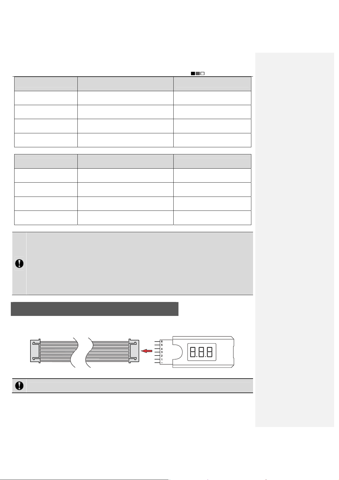
Use a Battery Indicator to Detect the Battery Level
Check the battery level before using the battery; in case of low battery level, charging is required. Insert the pins of
the battery indicator into the flat cable connector, as shown in the figure below.
Notice: The black wire should be connected to “– ” during connection.
Insert the other end of the flat cable into the port on the power battery as directed by the arrow in the figure below.
After connection, the battery indicator first displays the total voltage (25.2V), and then displays the voltage
- 3 -

Unmanned Aircraft System
Professional·Advanced
information of each battery cell in sequence: ALL (total voltage), No. 1, No. 2. No. 3, No. 4, No. 5 and No. 6.
Notice: The voltage difference between battery cells shall not exceed 0.1V; otherwise, the battery shall not
be used any longer.
Charge the Power Battery of the UAV
1. Connect the battery to the charger
The power battery of the UAV is provided with a special balanced smart charger which is designed with a
high-performance microprocessor and professional control software. This charger can be used to charge four
batteries simultaneously. Please connect the battery to the charger according to the following steps:
Step Illustration Description
Step 1:
Step 2:
Step 3:
Step 4:
Connect the two charger wires
according to the figure, and pay
attention to the polarity of terminals.
Select the charging port
corresponding to the number of the
cells (6S for power battery of the
UAV); connect the power plug after
connecting to the charging port.
Complete connection.
Connect the charger to AC 220V
power supply with the supplied power
cord; 4 LED indicators of the charger
will be on and then you can set the
parameters of the charger.
- 4 -
Unmanned Aircraft System
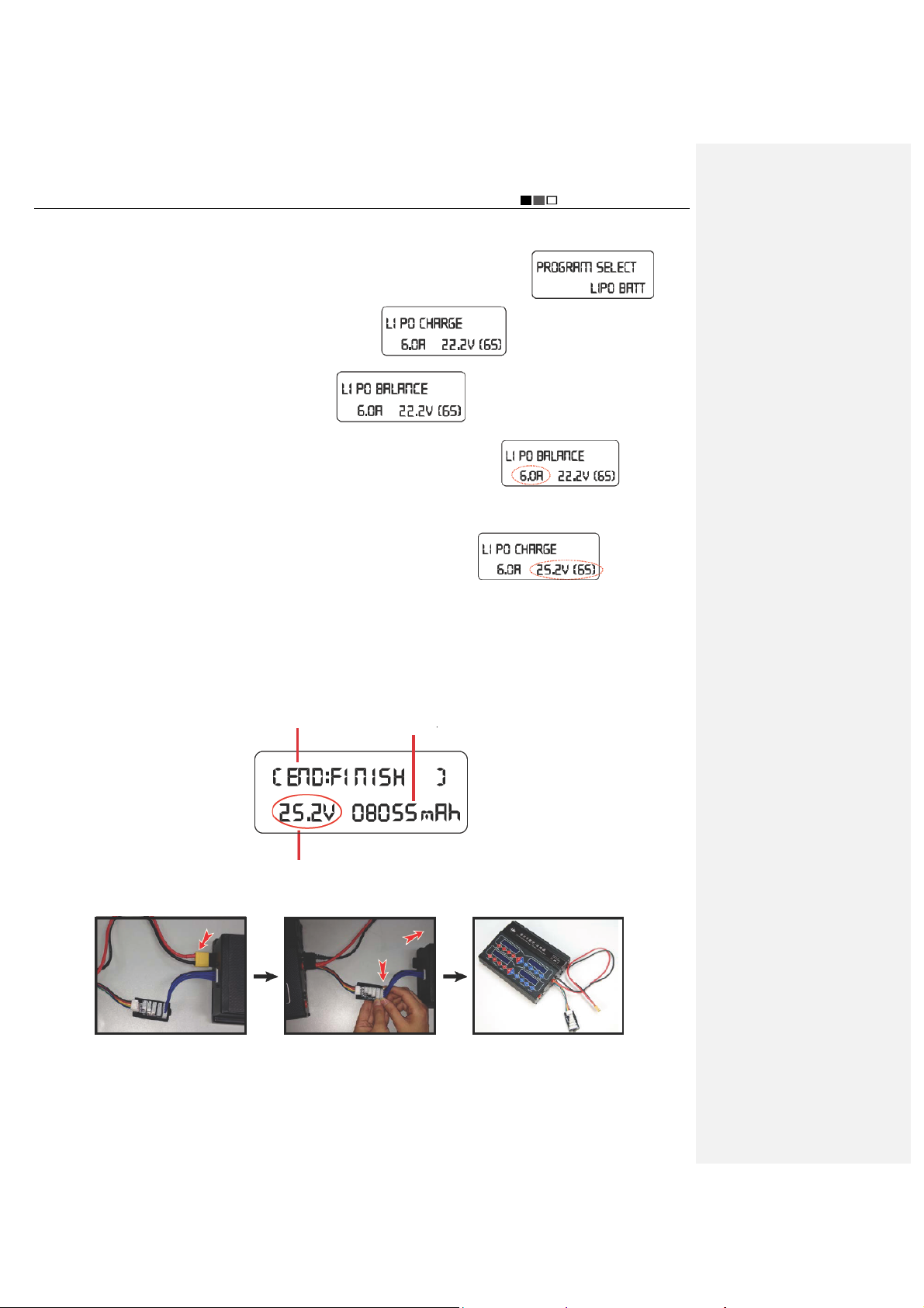
2. Set parameters and start charging
After the battery is connected to the charger, set the parameters for the charger as follows:
Professional·Advanced
1) Press “START” to select a battery type, and call out LiPo BATT; the screen displays:
2) Press “START” for confirmation, and the screen displays:
select LiPo BALANCE, and the screen displays:
; then press “DEC.” or “INC.” to
.
3) Press “START” again for confirmation, and the current value begins to pulsate:
.
; press
“DEC.” or “INC.” at this moment to decrease or increase the current value; press “START” for confirmation after
the current is adjusted to the proper value.
4) After confirmation of the current value, the voltage value begins to pulsate:
; press “DEC.”
or “INC.” to select the corresponding voltage of the battery; press “START” for confirmation after the voltage is
adjusted to “25.2V”.
5) After setting all parameters, long press “START” for 2s, and the charger begins to detect the battery; after
successful detection, press “START” to start charging.
3. Complete charging of the battery
After charging is completed, the charger sends out beep sounds, and the screen displays the following information:
Charging completed
Charged capacity of battery (mAh)
Battery voltage after charging is completed (V)
At this moment, you can disconnect the charger from the battery according to the following steps:
First, pull out the yellow
connector that is connected
to the battery
Then, pull out the two
connectors of the flat cable
in the directions of arrows.
Last, pull out the charger
wires, or leave them there
for future charging
- 5 -
Unmanned Aircraft System
Professional·Advanced
To avoid short circuit caused by accidental contact between the positive and negative connectors, which may
further result in damage of the battery or other safety accidents, DO NOT pull out the charger wires from the charger
before the power plug is disconnected.
Precautions for Use of Lithium Battery
1. Do not disassemble or restructure the battery;
2. Do not short-circuit the battery;
3. Do not use the battery near heat sources;
4. Do not drop the battery in water or get it wet;
5. Do not charge the battery near fire or in the sun;
6. Do not impact or drop the battery;
7. Do not use the battery when it is severely damaged or deformed;
8. Do not charge the battery in reverse polarity or over-discharge it (charging the battery in reverse polarity or
over-discharging it may result in swelling, fluid leaking, cell breakdown or even explosion of the battery);
9. Do not connect the battery in reverse polarity;
10. Any waste battery should be recycled in an environment-friendly way;
11. If the battery will be idle for a long time, the battery should be taken out and charged once every six months to
24V for storage, so as to maintain the battery performance and prolong its service life.
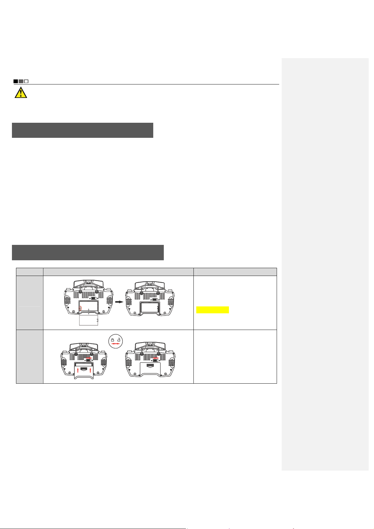
Charge the Battery of the Remote Control
1. Install the battery
Step Illustration Description
Install the battery into the battery
Step 1
Step 2
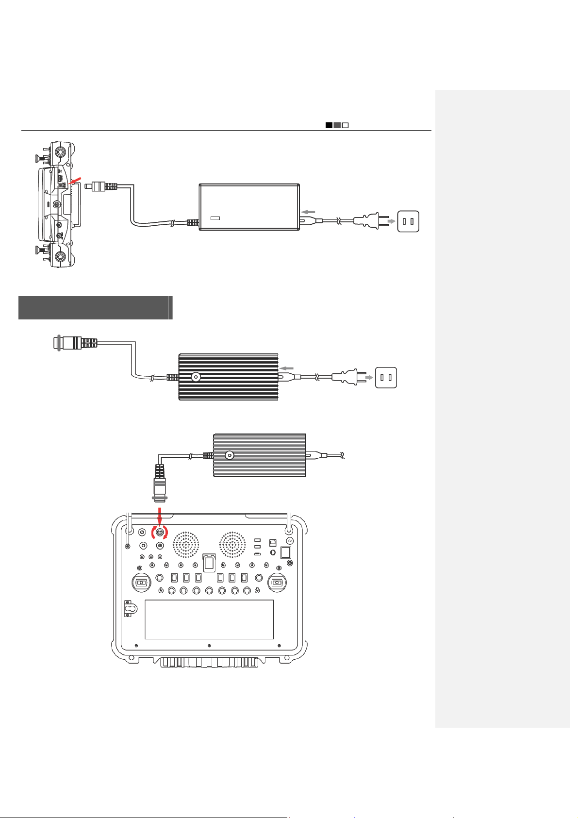
2. Connect the adapter
First, connect the power cord of the adapter to the adapter; then, insert the adapter plug into the power outlet; last,
insert the round end of the adapter into the DC jack of the remote control.
- 6 -
compartment by aligning with the
metal contacts.
Turn the battery snap rightward
and meanwhile push the battery
cover upward, as shown in the
figure; when the battery cover is
properly installed, the battery snap
will automatically rebound to the
left side.
Unmanned Aircraft System
Professional·Advanced
3. The battery has been charged fully if the yellow indicator light on the remote control is always on.
Charge the Ground Station
1. First, connect the power cord of the adapter to the adapter; then, insert the adapter plug into the power outlet.
Insert the other end of the adapter to the charging jack of the ground station; clockwise rotate the metal ring on the
charging plug to make the charging plug in close contact with the charging jack without looseness.
Tighten clockwise after insertion
2. Charging state
During charging of the ground station, the charging indicator light is red; when it is charged fully, the charging
- 7 -
Unmanned Aircraft System
Professional·Advanced
indicator light turns green.
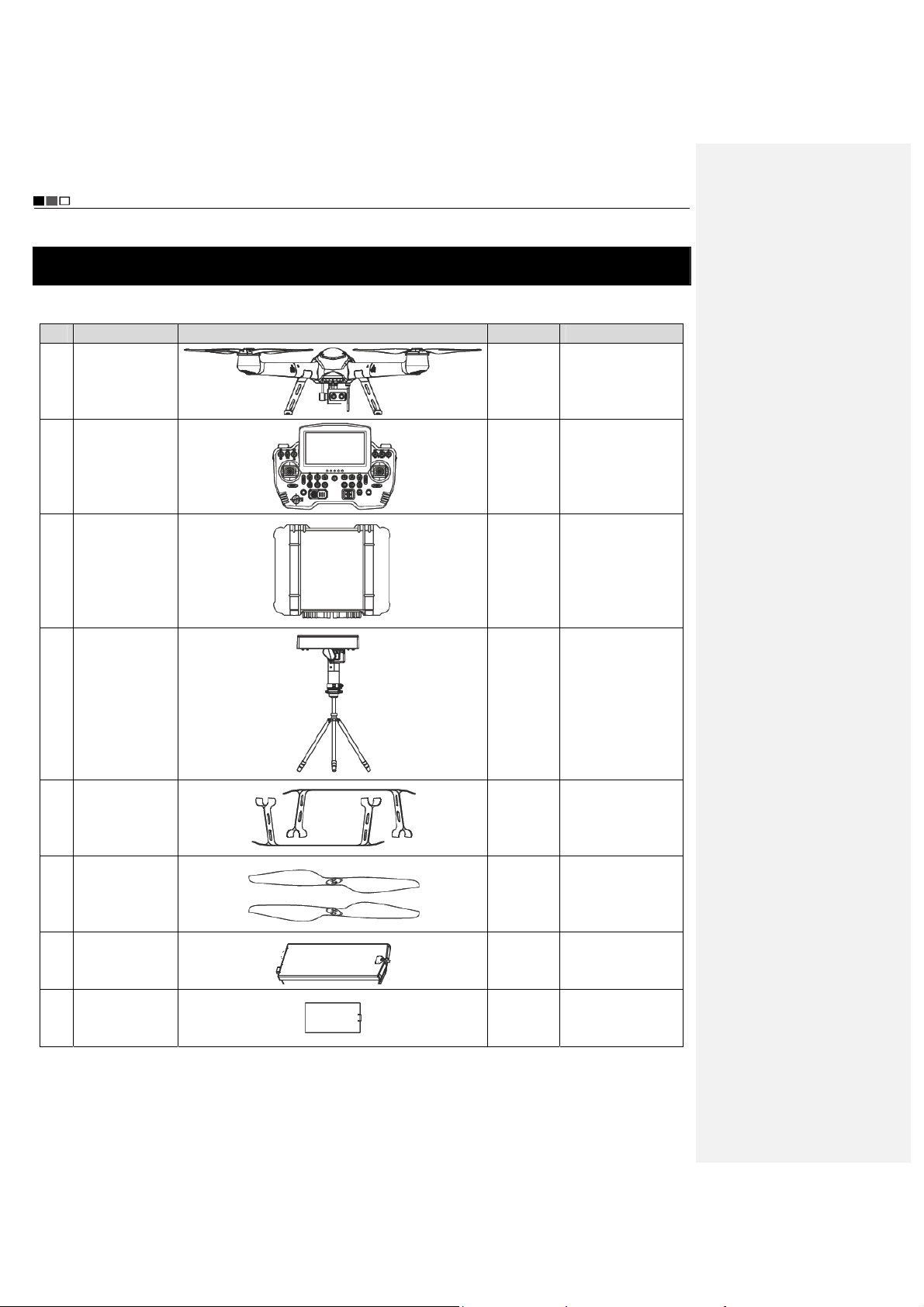
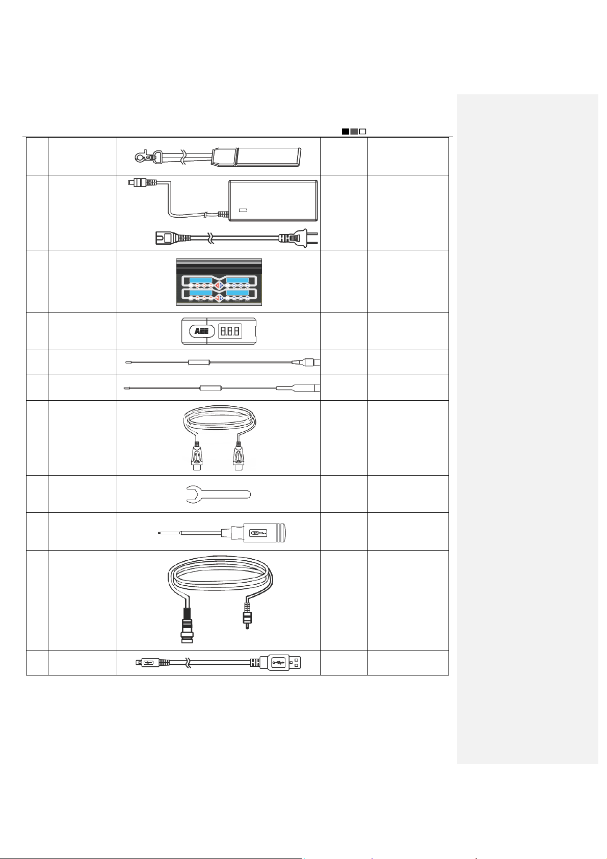
List of Components
The following components are included in the package of this product. Please check carefully at the time of
purchase. In case of any missing component or damage, please feel free to contact us.
No. Name Illustration Quantity Description
Main unit of
1
Main unit of
2
remote control
Main unit of
3
ground control
aircraft
station
2 sets
1 set
1 set
Auto tracking
4
5 Undercarriage
6 Propeller
7
8
antenna
Power battery
for flight
Battery of
remote control
- 8 -
1 set
4 sets
(2pcs/set)
4 sets
(4pcs/set)
2pcs of 20,000mAh
4pcs
1pc
battery and 2pcs of
15,000mAh battery
Include 64pcs of
screw
Capacity:
4,000mAh
Unmanned Aircraft System
Professional·Advanced
9 Strap
1pc
10 Adapter 1pc
Include power cord,
11 Battery charger
1 set
charger connecting
cable
Battery voltage
12
indicator
2pcs
13 Radio antenna 2pcs
14 Video antenna 4pcs
HDMI output
15
cable
2pcs
For installing the
16 Wrench (14mm)
Screwdriver
17
(2.5mm)
18 AV output cable
auto tracking
antenna
1pc
For removing the
propellers
2pcs
19 USB data cable 3pcs
- 9 -
Unmanned Aircraft System
Professional·Advanced
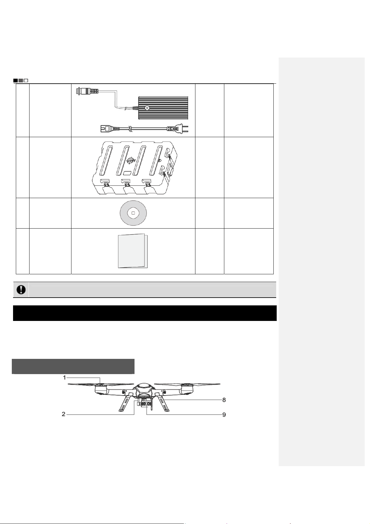
Adapter for
20
ground control
station
1pc
21 Protection box
22 CD-ROM
23
Instruction
Manual
Notice: The accessories of actual product may vary slightly, and the above figures are for reference only.
4pcs
1pc
1 copy
Unmanned Aerial Vehicle
The unmanned aircraft system integrates the flight control software, radio modem, HD image transmission, control
joysticks, mission control buttons, etc., enabling users to conveniently view flight data and real-time images during
flight; through control by the remote control or ground station, the UAV can realize spot hover, routed flight and other
types of real-time route monitoring and mission control.
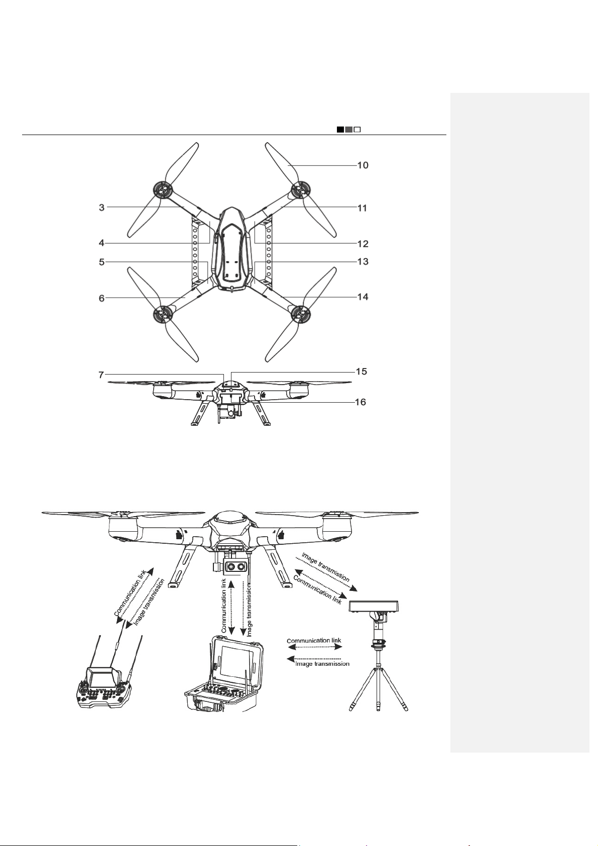
Guide for Components of the UAV
- 10 -
Unmanned Aircraft System
Professional·Advanced
[1] Motor [2] PTZ [3] Removable arm A1 [4] Frame arm A1
[5] Frame arm B2 [6] Removable arm B2 [7] Power key [8] Undercarriage
[9] Airborne camera [10] Propeller [11] Removable arm B1 [12] Frame arm B1
[13] Frame arm A2 [14] Removable arm A2 [15] Power indicator [16] Battery plug switch
Configuration of F100 main unit system
- 11 -
Unmanned Aircraft System
Professional·Advanced
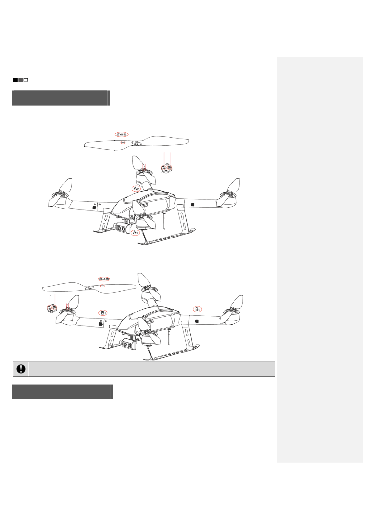
Install the Propeller Blades
Install the propeller blades marked with letter “L” on the removable arms A1 and A2, respectively, as directed by the
dashed lines in the figure below; use the supplied screwdriver to tighten the set screws by applying proper force;
note that screw glue should not be used.
Install the propeller blades marked with letter “R” on the removable arms B1 and B2, respectively, as directed by the
dashed lines in the figure below; use the supplied screwdriver to tighten the set screws by applying proper force;
note that screw glue should not be used.
Notice: Wrong installation of clockwise and counter-clockwise propeller blades will inevitably result in errors
in the UAV lift system, further leading to unpredictable consequences.
Install the Removable Arms
Insert the removable arms marked with “A1”, “A2”, “B1” and “B2” respectively into the frame arms A1, A2, B1 and B2
on the UAV, as shown in the figure below:
- 12 -
Unmanned Aircraft System
Professional·Advanced
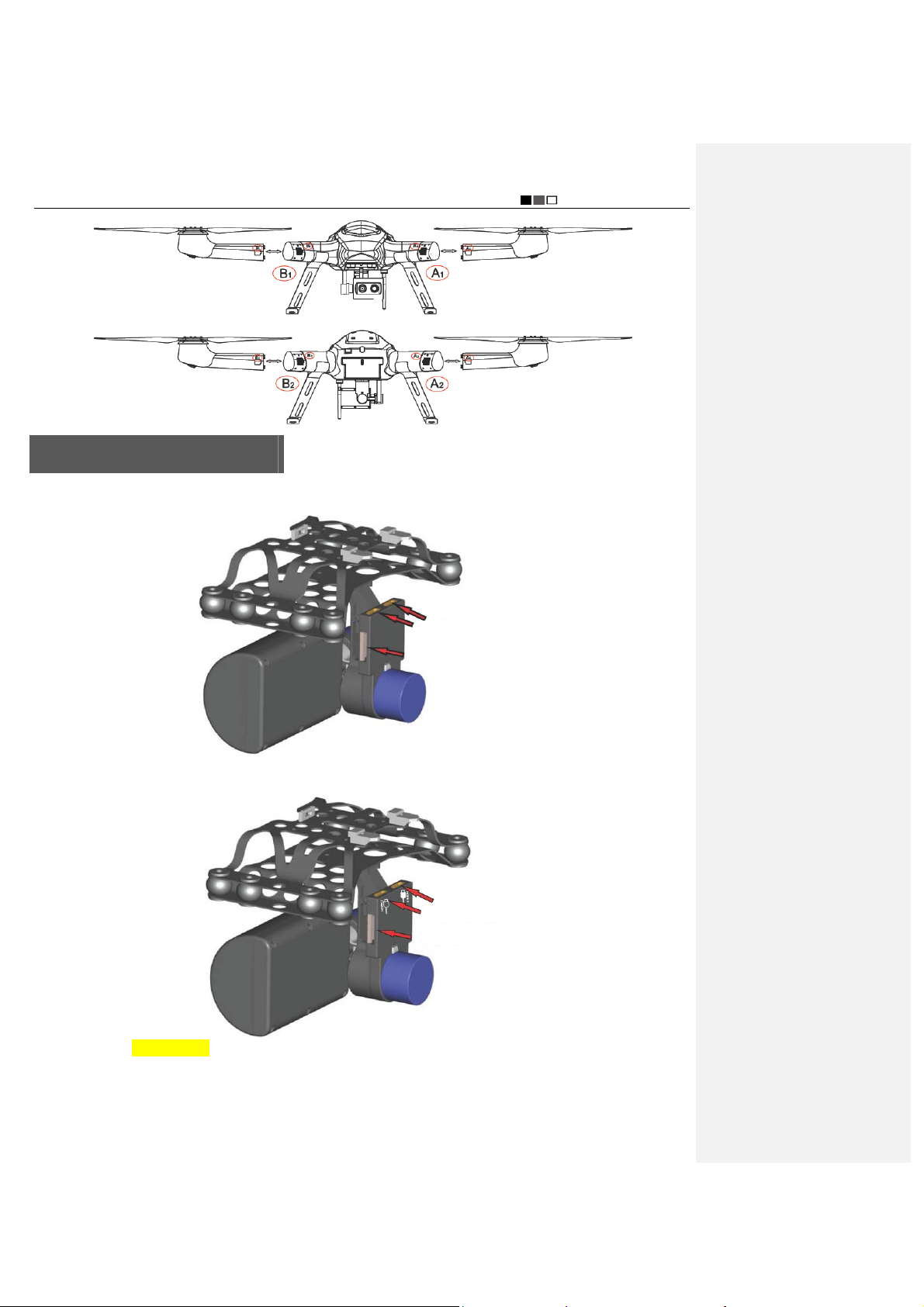
Install the Airborne Camera
1. There are two HDMI video cables and one PTZ control cable at the position where the airborne camera is
installed, as shown in the figure below:
The yellow ports are forHDMI cables
The white port is for PTZ control cable
2. Properly connect the HDMI cables and the PTZ control cable to the airborne camera (insert the white HDMI cable
into the port marked with a white block), as shown in the figure below:
Insert the white HDMI cable
Insert the black HDMI cable
Insert the white PTZ control cable
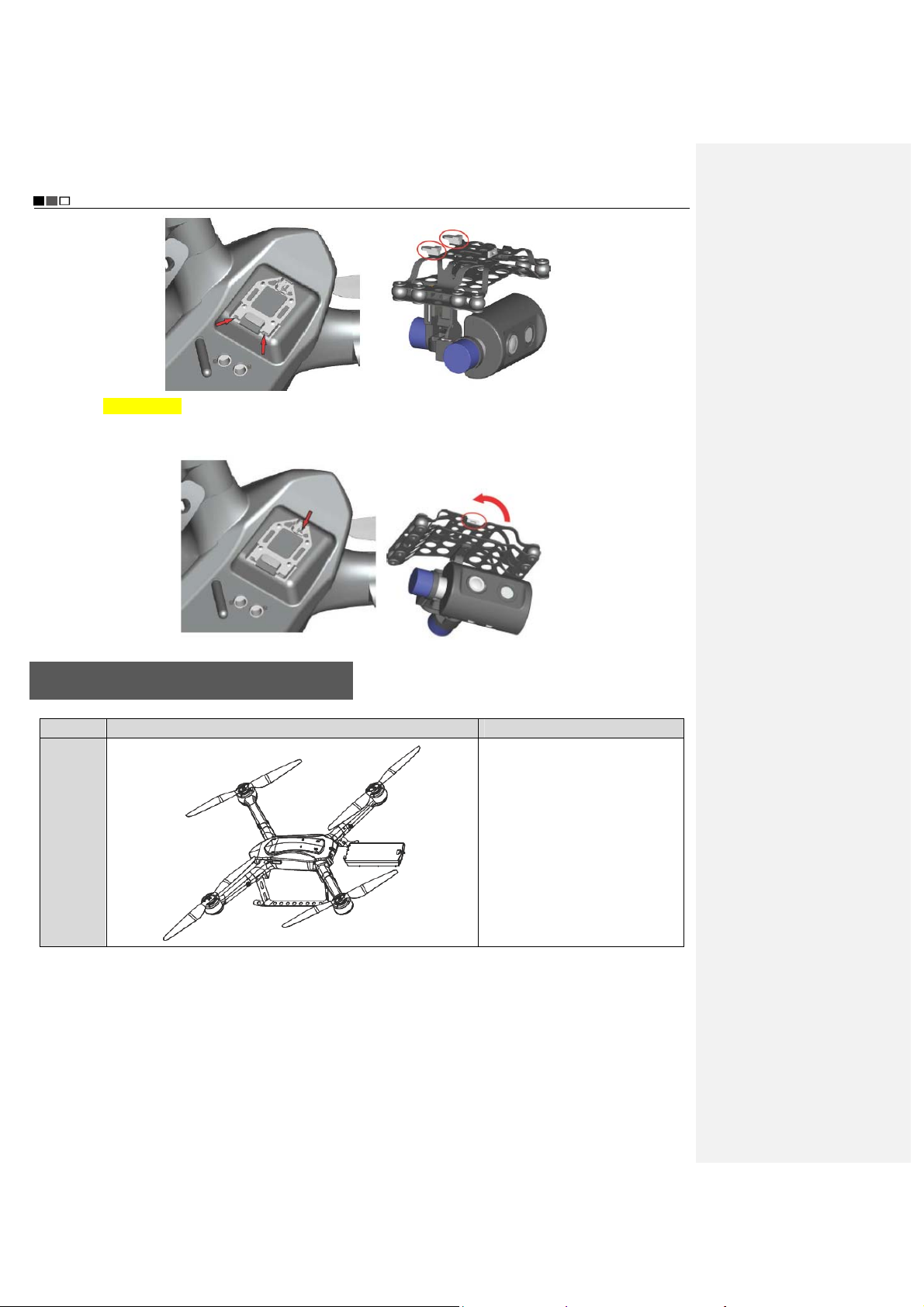
3. Attach the two clamping pins of the PTZ (as shown in the red circles) by aligning with the PTZ sockets (as directed
by the red arrows), as shown in the figure below:
- 13 -
Unmanned Aircraft System
Professional·Advanced
4. After the clamping pins are attached, press the other end of the PTZ upward until the snap-fit joint (as shown in
the red circle) clamps the PTZ and the PTZ does not shake, as shown in the figure below; at this moment, the PTZ is
fixed.
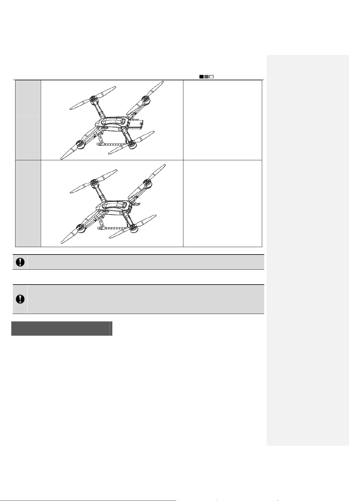
Install the Power Battery of the UAV
Step Illustration Description
Step 1
Make the battery connector face
the battery compartment
- 14 -
Unmanned Aircraft System
Professional·Advanced
Step 2 Push the battery inward
Push the battery into the battery
Step 3
Notice: Please make sure that the power switch of the UAV is in the OFF state during installation of the
battery.
After completion of the above three steps, horizontally place the UAV on the ground (a flat ground is recommended);
then turn ON the power switch of the UAV.
Notice: The UAV will carry out self-checking 3-5s after it is powered up; at this moment, please DO NOT
move the UAV or operate the remote control (before self-checking, please make sure that the power switch
at the tail of the UAV is in the ON state); after self-checking is completed, if “beep…beep beep beep beep
beep beep…beep” sound is heard, it indicates the self-checking is passed.
compartment until the battery
snap is fastened to the aircraft
body.
Preparations before Take-off
1. Check the batteries of the UAV and the remote control to see if the battery level is high enough; in case of low
battery level (<22.2V), please replace the battery.
2. Check the propellers of the UAV to see if they are tightened.
3. Make sure that the manual/auto fly switch of the remote control is in the manual fly mode.
4. Check the servo; in case of any anomaly (indication bars do not jump or indication is inaccurate during
checking), please calibrate the joysticks. (For servo checking and joystick calibration, please make sure the
power switch of the UAV is in the OFF state, in order to avoid accidental take-off of the UAV.)
5. Turn off the power switch after the UAV is placed at the take-off position; to ensure safety, there should be no
obstacle at the take-off position within the radius of 10m around the UAV.
6. Turn on the power switch of the UAV; for outdoor flight, GPS satellite positioning is required; take-off is allowed
only when the GPS signal strength indicator is greater than or equal to 6.
7. In order to avoid accidents, please do not simultaneously start two UAVs within a short distance whenever
- 15 -
Unmanned Aircraft System
Professional·Advanced
possible.
8. Before take-off, please make sure that the video and radio antennas have been properly installed to avoid
influence on the flight or the video receiving distance, or damage to the UAV or the transmitter module inside
the remote control.
9. When the remote control is used to control the UAV, please make sure that the option of “Send Joystick Data” in
the ground station software is not checked before take-off; when the ground station joystick is used to control
the UAV, please make sure that the remote control is in the OFF state before take-off.
Control the Flight with the Remote Control
The remote control is specially developed for the unmanned aircraft system to make it convenient for controlling the
flight of the UAV. The remote control can independently control the flight of the UAV, and can display the flight status
of the UAV and the real-time images from the airborne camera simultaneously.
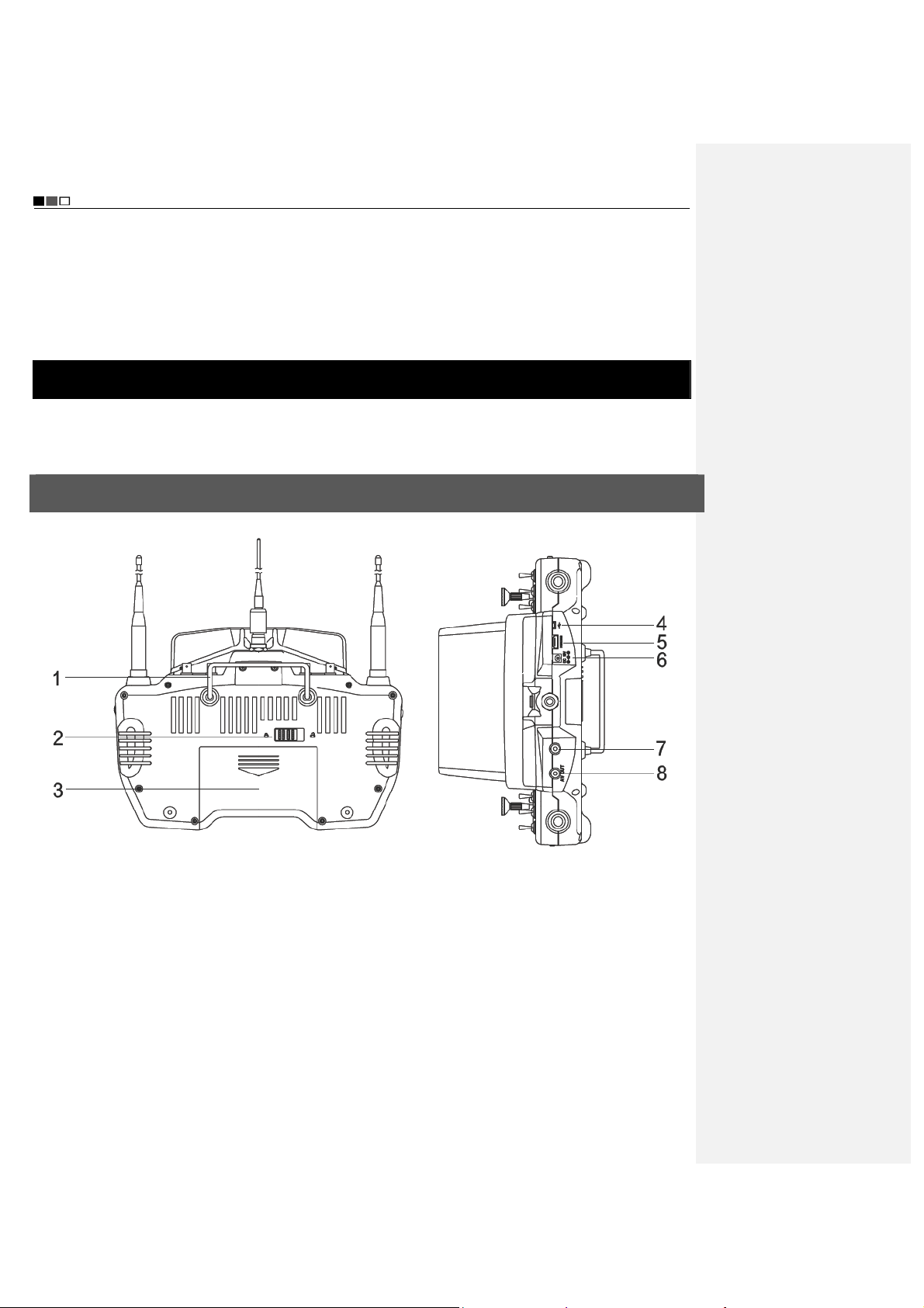
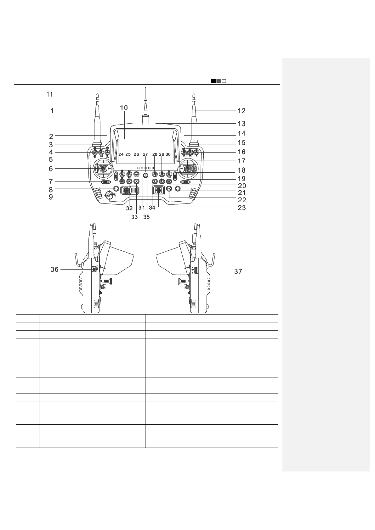
Guide for Components of the Remote Control and Description of Button Functions
The components of the remote control and the button functions are shown as follows:
[1] Remote control handle [2] Battery cover snap [3] Battery cover [4] USB port
[5] HDMI port [6] Adapter port [7] Reserved port [8] AV port
- 16 -
Unmanned Aircraft System
Professional·Advanced
No. Name Function Description
1 Video antenna (HD) Receives HD video signals
2 Reserved button /
3 Airborne camera switch Switches the airborne camera
4 Reserved button /
5 Throttle trim button Trims the throttle channel
6 Left joystick
Manually controls the flight of the UAV, including throttle
and rudder channels
7 Rudder trim button Trims the direction channel
8 Reserved button /
9 Reserved button /
The operator can view the attitude, longitude and
10 Remote control screen (with touch function)
latitude, battery level, height and other relevant
information of the aircraft on the screen
11 Radio antenna
Transmits flight commands; receives flight attitude,
sensor information, longitude and latitude, etc.
12 Video antenna (HD) Receives HD video signals
- 17 -

Unmanned Aircraft System
Professional·Advanced
13 Sunshade
14 Reserved button /
15 Reserved button /
16 Manual/auto mode switch Switches between manual and auto fly modes
17 Right joystick
18 Pitch trim button Trims the pitch channel
19 Roll trim button Trims the roll channel
20 One-key go home button Controls the aircraft to go home autonomously
21 Reserved button /
22 Reserved button /
23 Remote control power switch Turns on/off the remote control
24 Airborne video recording button
25 Reserved button /
26 Reserved button /
27 Strap hole Hangs the strap
28 Reserved button /
29 Reserved button /
30 Local recording button
31 Airborne photo shooting button Controls photo shooting of the airborne camera
32 Reserved button /
33 Menu button It allows you to enter or exit the menu setting interface
34 One-key take-off button Controls autonomous take-off of the aircraft
35 One-key landing button Controls autonomous landing of the aircraft
36 Airborne zoom knob Controls zooming of the camera
37 PTZ control knob
Reduces the influence of strong light when the operator
is viewing information on the screen
Manually controls the flight of the UAV, including roll and
pitch channels
Controls video recording of the airborne device
Turn it downward to enable airborne video recording;
turn it upward to disable airborne video recording
Saves a video currently displayed on the display
terminal to the local memory
Controls up-and-down rotation of the PTZ; the lens
angle can be adjusted; the maximum and minimum
angles of elevation are 15° and -90°, respectively
Preparations for the Remote Co ntrol
Antenna Installation
Install the antennas shown below at the corresponding positions of the remote control and clockwise tighten them.
The shapes of antennas and the antenna ports on the remote control are shown as follows:
Video antenna
Radio antenna
- 18 -

Unmanned Aircraft System
Professional·Advanced
Video antenna port Video antenna port
Radio antenna port
Notice: Please make sure that the video and radio antennas have been properly installed to avoid influence
on the flight or the video receiving distance, or damage to the UAV or the transmitter module inside the
remote control.
Sunshade Installation
Insert the sunshade along the groove direction until the snap at the back of the sunshade is attached to the snap
holder on the remote control, as shown in the figure below:
Sunshade removal
To remove the sunshade, use your fingers to hold the two sides of the snap; pull the sunshade snap outward to
separate it from the snap holder; then, pull the sunshade upward along the groove direction to separate the
sunshade from the remote control. See the figure below:
- 19 -

Unmanned Aircraft System
y
Professional·Advanced
Parameter Setting for the Remote Control
The information displayed on the screen upon power-on is shown as follows:
Indication of airborne
video recording status
Heading indicator
Indication of local recording
status of remote control
批注[e1]:下图跟提供的英文界面
图有些区别,请确认是否替换
Indication of batter
level of UAV
Indication of GPS
signal strength
Indication of speed
Longitude and latitude
of take-off position
Throttle trim
Press “M” to enter the “Setting” interface of the remote control:
value
Course trim
Indication of camera clock
- 20 -
Roll trim
Indication of battery
level of remote
control
Horizon instrument
(indication of roll and
pitch attitudes)
Indication of height
Longitude and
latitude of
current position
Pitch trim

Unmanned Aircraft System
Professional·Advanced
* * Servo Checking
Check if the functions of joysticks, fly mode switch and PTZ control knob on the remote control are normal through
“Servo Checking”. Here are the steps of servo checking:
1) Press “M” to enter the “Setting” interface the remote control.
2) Touch “Servo Checking” to enter the setting interface:
3) At this moment, turn the left and right joysticks by the maximum angle possible, toggle the fly mode switch and
rotate the PTZ control knob, and the relevant indication bars will pulsate correspondingly; the functions of roll,
pitch, throttle, course, auto fly switch and angle adjustment of airborne camera can be checked.
Notice: Servo checking must be carried out before take-off; before servo checking, please make sure that
the power switch of the UAV is in the OFF state, in order to avoid accidental startup of the UAV.
* Joystick Calibration
Touch “[Start]” for joystick calibration in the “Servo Checking” interface in the above step; turn the left and right
joysticks for 5-10 circles by 360° to enter the state of joystick calibration; indication bars of roll, pitch, throttle and
course will pulsate correspondingly; click “DONE” to finish the calibration process. Carry out servo checking after
completion of calibration; it is OK if servo checking shows normal result; otherwise, recalibration is required.
批注[e2]:下图跟提供的英文界面
图有些区别,请确认是否替换
批注[e3]:下图跟提供的英文界面
图有些区别,请确认是否替换
Notice: Before joystick calibration, please make sure that the power switch of the UAV is in the OFF state, in
order to avoid accidental startup of the UAV.
* Airborne Camera Setting
Touch to enter the following interface:
- 21 -

Unmanned Aircraft System
Professional·Advanced
At this moment, the “camera switch” can be adjusted to select the desired camera and enter the following setting
interface. The “Airborne Camera Setting” interface consists of video setting, photo setting, etc. (Video setting:
photo setting:
; local setting of airborne camera: )
Video Setting
Image Resolution Setting
;
- 22 -

PAL-system 1920×1080 50f 16:9 1920×1080 25f 16:9
Photo Setting
Photo Resolution
12.0M (4000×3000 4:3) default 16.0M (4608×3456 4:3 )
Unmanned Aircraft System
Professional·Advanced
Local Setting of Airborne Camera
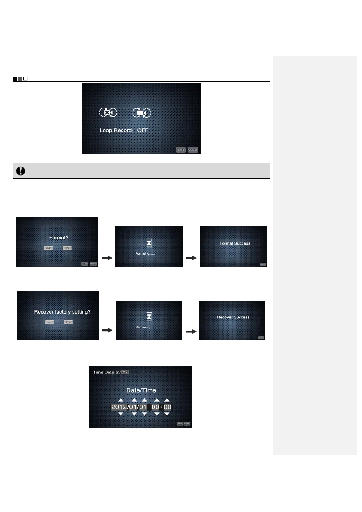
Touch
to enter the “Local Setting of Airborne Camera” interface:
Loop Record: ON, OFF
No matter whether “Loop Record” is ON or OFF, recording is saved as a segment file by each 10 min. When
“Loop Record” is ON, if the space of the memory card is not enough, the first segment of recording file will be
overwritten automatically.
批注[e4]:提供的英文界面图中没
有找到下图
批注[e5]:下图原稿中是“开”,而
提供的英文界面图中是 OFF,是否
可以替换?
- 23 -
Unmanned Aircraft System
Professional·Advanced
Notice: During airborne video recording, the function of loop record is valid only when the free memory
space of the camera is more than 200M.
Formatting
The airborne camera can be formatted to remove all files in it. Make sure you do not need the data before
formatting!
Ye s
Recover Factory Setting
This operation will restore all settings of this device to the factory settings.
Ye s
Date Setting
a. Touch “Date Setting” to enter the “Time Display” setting interface:
- 24 -

Unmanned Aircraft System
Professional·Advanced
b. Touch “ ” or “ ” corresponding to settings of “Year, Month, Day, Hour, and Minute”, to complete the
settings of Year, Month, Day, Hour, and Minute.
c. Touch “Save” to complete setting.
Notice: When the state of “Time Display” is ON, after “Save” is touched to complete setting, date and time
will be indicated at the lower right corner of the video and photo; when the state of “Time Display” is OFF,
there will be no such indication.
Language Setting
1. Press “M” to enter the “Setting” interface of the remote control.
2. Touch “Language Setting”.
y Language options: Simplified Chinese, English
3. After selecting the desired language, touch “Save” to complete setting.
Software Version Info
Calibrate the UAV
Calibration of Accelerometer, Gyroscope and Compass
Before take-off, horizontally place the UAV on the ground; turn on the remote control, and check if the attitude of the
UAV is horizontal and if the numeric values indicated on the compass and the barometer are proper. If the remote
control displays titled attitude of the UAV on the horizontal ground or error of compass or height data, please
calibrate the UAV according to the following steps:
- 25 -

Unmanned Aircraft System
Professional·Advanced
Step Illustration UAV Remote control
1
Turn the left joystick of the remote control to
the lower right corner and the right joystick to
the lower left corner (keep this motion for 3-5s)
2
Place the UAV horizontally
Turn the left joystick of the remote control to
the lower right corner and the right joystick to
the lower left corner (keep this motion for 3-5s)
Place the UAV vertically with its
nose facing downward
Accelerometer calibration
The calibration is
completed when
the numeric value
of battery level
indicated on the
display screen of
3
Turn the left joystick of the remote control to
the lower right corner and the right joystick to
the lower left corner (keep this motion for 3-5s)
Place the UAV with its nose
facing rightward
the remote
control and that
on the compass
change from
certain value to 0,
and then change
to certain value
from 0.
4
Turn the left joystick of the remote control to
the lower right corner and the right joystick to
the lower left corner (keep this motion for 3-5s)
5
Turn the left joystick of the remote control to
the lower right corner and the right joystick to
the lower left corner (keep this motion for 3-5s)
Place the UAV vertically with its
nose facing upward
Place the UAV with its nose
- 26 -

facing leftward
Unmanned Aircraft System
Professional·Advanced
6
Turn the left joystick of the remote control to
the lower right corner and the right joystick to
the lower left corner (keep this motion for 3-5s)
Place the UAV with its bottom
facing upward
Gyroscope calibration
The calibration is
completed when
Turn the left joystick of the remote control to the
upper left corner and the right joystick to the upper
Place the UAV horizontally
the UAV can be
started
right corner (keep this motion for about 30s)
Compass calibration
First, hold the aircraft horizontally by hand and turn
horizontally for 2 circles; then, hold the aircraft vertically
Turn the left joystick of the remote control to the
upper right corner and the right joystick to the
upper left corner (keep this motion for 3-5s)
by hand and turn horizontally for 2 circles. The
calibration is completed when the numeric value of
battery level indicated on the display screen of the
remote control and that on the compass change from
certain value to 0, and then change to certain value
from 0.
Notice: For outdoor flight, please make sure that the numeric value on the GPS signal strength indicator is
greater than or equal to 6; before startup of the UAV, please make sure that all switches on the remote
control are in the up position.
Throttle Calibration
First, power off the UAV, and turn the manual/auto fly switch of the remote control to the auto fly position, and push
the throttle to the highest position; power on the UAV; push the throttle to the lowest position when two “beep”
sounds are heard from the UAV; when the UAV makes six “beep” sounds, turn the manual/auto fly switch of the
remote control to the manual fly position. At this moment, throttle calibration is completed.
Notice: The throttle has been calibrated before delivery of the UAV, and recalibration is unnecessary. This
calibration is required when normal flight is influenced by inconsistent rotational speed of the four motors of
the UAV after the throttle is pushed before take-off. Before throttle calibration, please remove the propeller
blades and follow the above steps.
- 27 -

Unmanned Aircraft System
r
r
Professional·Advanced
Start the UAV
Start the UAV in the following way:
Turn the left joystick to
the lower left corne
Release the joysticks immediately after the propeller blades begin rotating; at this moment, the UAV enters the
startup state; when the left joystick is turned upward, the UAV will begin climbing up.
Notice: For outdoor flight, please make sure that the numeric value on the GPS signal strength indicator is
greater than or equal to 6; before startup of the UAV, please make sure that the remote control antennas
have been properly installed and all switches are in the up position.
Turn the right joystick
to the lower right corne
Direction Control
Directions of the UAV are defined in the figure below:
Front
(Nose)
Left Right
Rear
(Tail)
- 28 -

See the following table for details:
Joystick Attitude of UAV Illustration
Climb Upwards
The motor speed and
the propeller speed
increase. The climbing
speed increases as
Horizon
the joystick turning
angle enlarges.
Turn the left joystick
forwards, and keep
the right joystick in the
original position.
Go downwards
The motor speed and
the propeller speed
decrease. The
Horizon
descending speed
increases as the
joystick turning angle
enlarges.
Turn the left joystick
backwards, and keep
the right joystick in the
original position.
Fly forwards
The nose faces
downwards; the UAV
inclines forwards and
flies along the nose
Horizon
direction. At this
moment, it is needed
to slightly push
forward the throttle to
Keep the left joystick
in the original position,
and turn the right
joystick forwards
adjust the flight
altitude so as to
realize horizontal flight
of the UAV.
Unmanned Aircraft System
Professional·Advanced
Fly forwards
(nose direction)
Right view
Pitch
angle
- 29 -

Unmanned Aircraft System
Professional·Advanced
The tail faces
downwards; the UAV
inclines backwards
and flies along the tail
direction. At this
moment, it is needed
to slightly push
forward the throttle to
Keep the left joystick
in the original position,
and turn the right
joystick backwards
adjust the flight
altitude so as to
realize horizontal flight
of the UAV.
The UAV inclines
rightwards. At this
moment, it is needed
to slightly push
forward the throttle to
adjust the flight
altitude so as to
realize horizontal flight
of the UAV.
Keep the left joystick
in the original position,
and turn the right
joystick rightwards
At this moment, it is
needed to slightly
push forward the
throttle to adjust the
flight altitude so as to
realize horizontal flight
of the UAV.
Keep the left joystick
in the original position,
and turn the right
joystick leftwards
Fly backwards
Fly rightwards
Fly leftwards
Fly backwards
(tail direction)
Pitch angle
Horizon
Roll angle
Right view
Aircraft tail
Roll leftwards
Aircra ft tail
Horizon
Roll rightwards
Roll angle
Horizon
- 30 -

Turn the left joystick
rightwards, and keep
the right joystick in the
original position.
Turn the left joystick
leftwards, and keep
the right joystick in the
original position.
Unmanned Aircraft System
Professional·Advanced
Rotate the nose
rightwards
(rotate clockwise)
Rotate the nose
leftwards
(rotate
counter-clockwise)
The throttle lever of the remote control is the power lever that controls the propeller speed; it can control the
rising and descending of the UAV. The throttle lever should be pushed gently, and fast change should be avoided.
The right joystick of the remote control is the direction lever; the UAV goes leftwards, rightwards, forwards and
backwards respectively when the right joystick of the remote control is pushed leftwards, rightwards, forwards and
backwards.
During manual fly, the forward motion direction of the UAV can be corrected by combining the right joystick
while operating the left joystick. When the UAV is in the air, any unpredictable airflow change will cause drifting and
autorotation of the aircraft, which breaks the original balance. In such case, the UAV will inevitably rotate and drift.
Therefore, comprehensive control measures should be taken.
Go Home and Shut down the UAV
One-key Go Home
When the GPS signal strength is greater than or equal to 6 during outdoor flight, press the “One-key Go Home”
button to send the command requiring the UAV to go home immediately; after receiving the command, the UAV will
enter the go-home mode and hover in the air after returning to the take-off position.
Notice: In the manual fly mode, 10s after the UAV receives and executes the go-home command, you can
turn the auto/manual fly switch downwards and then upwards once to go to the manual fly control mode.
During landing of the UAV, please make sure that there is no movable obstacle or person within 10m around
the landing position in order to avoid landing accident.
- 31 -

Unmanned Aircraft System
r
r
Professional·Advanced
Shut down the UAV
Shut down the UAV in the following way:
Turn the left joystick to
the lower left corne
Notice: During flying of the UAV, the above startup and shutdown operations are forbidden; or else,
unpredictable consequences may be caused. When operation is completed, please timely turn off the power
switch of the UAV and take out the battery to avoid continuous consumption of the battery.
Turn the right joystick
to the lower right corne
Control the Flight with the Ground Station
The ground control station (hereinafter referred to as the “ground station”) is one of the ground control devices for
the unmanned aircraft system. Compatible with the main functions of the hand-held remote control, it allows you to
easily edit waypoints on a 3D map, set air routes, view real-time information such as coordinates, flight attitude,
speed and video sent back by the UAV. The UAV can fly autonomously along the air route preset in the ground
station software, and real-time videos and other information sent back by the UAV can be received and saved.
Functions and Features of the Ground Station
* With the waypoint editing function, at most 100 waypoints can be added.
* Check the UAV status in a real-time way, including such information as battery level, speed, altitude, longitude
and latitude.
* Automatic control of take-off and landing.
* With the joystick control function, manual fly can be realized.
* Air routes can be set, enabling the UAV to fly autonomously.
* With the built-in high-capacity battery, it can satisfy the requirement of long-time outdoor use.
* With the powerful information processing function, it can simultaneously display satellite maps and real-time
videos of the UAV.
* It has the reliable multi-level protection function.
* It can control the working status of the airborne camera.
* It is equipped with a professional protection box.
- 32 -

Unmanned Aircraft System
Professional·Advanced
Panel Layout and Port Functions of the Ground Station
No. Name Function description
1 Display screen power cord Supplies power to the display
2
3 Support rod
4 Ground station indicator It is red when the main power switch of the ground station is turned on
5 Charge indicator
6 Reserved button /
7
8 Left joystick
9
10 DC power jack
11
12
13 HDMI port Outputs HD videos (HDMI)
14 USB port Connects external USB devices
Digital video transmission
antenna 1
Zoom “-”
Port for communication cable of
auto tracking antenna
Airborne video recording
indicator
Ground station heat emission
hole
Receives HD video signals
It is used to support the screen panel when the ground station panel is
open; it can be taken in when the panel is closed; use a screw to fix it
It is red during battery charging and green when the battery is fully
charged
Zoom control of camera: zoom out
Manually controls the flight of the UAV, including throttle and course
channels
Controls power supply to and communication with the auto tracking
antenna
Connects the external power adapter to supply power to the system and
charge the battery
It blinks when the airborne camera is recording videos; it is off if video
recording is not enabled
Emits heat from the ground station
- 33 -

Unmanned Aircraft System
Professional·Advanced
15 AV jack Outputs real-time videos sent back by the airborne camera on the UAV
16 RJ45 network jack Connects external networks
17
18 Power switch Connects to or disconnects from the main power
19 Radio antenna
20 Manual/auto fly switch Switches between manual fly and auto fly modes
21 Zoom “+” Zoom control of camera: zoom in
22 Right joystick Manually controls the flight of the UAV, including roll and pitch channels
23 Keyboard, mouse Operates the industrial computer
24 Airborne video recording switch
25 Airborne photo shooting button Controls photo shooting of the airborne camera
26 One-key routed flight button Commands the UAV to autonomously fly along the set route
27 One-key take-off button Controls autonomous take-off of the aircraft
28 One-key landing button Controls autonomous landing of the aircraft
29 One-key go home button Controls autonomous go-home of the aircraft
30 Reserved button /
31 Reserved button /
32 Local recording switch
33 Ground station starting switch Turns on the ground control station
34 Reserved button /
35 Camera switch Switches the airborne camera
36 Reserved button /
37 Reserved button /
38 Reserved button /
Digital video transmission
antenna 2
Receives HD video signals
Transmits flight commands; receives flight attitude, sensor information,
longitude and latitude, etc.
Controls video recording of the airborne device
Turn it downward to enable airborne video recording; turn it upward to
disable airborne video recording
Saves a video currently displayed on the display terminal to the local
memory
Preparations for the Ground Control Station
Open and Fix the Top Cover
Open the top cover of the ground control station and use the support rod to fix it:
- 34 -

Unmanned Aircraft System
Professional·Advanced
1. Slide rightward, and take out the support rod.
2. Rotate the support rod; install it by aligning it
with the support rod hole in the top cover; slide
the support rod leftward to lock it.
* Install the Antennas
Radio antenna Video antenna Auto tracking antenna
Radio antenna
There are two omnidirectional HD video antennas and one omnidirectional radio antenna. Clockwise rotate and fix
the antennas after they are aligned with the corresponding ports:
Video antenna
- 35 -

Unmanned Aircraft System
Professional·Advanced
No. 1 2 3 4
Port name
Startup
First turn on the main power switch, and then press the “Start Main Unit” button to start the ground control
station.
Port for communication cable of
auto tracking antenna
For short-distance operation, it is suggested the metal antenna should be used; for long-distance control, it
is suggested the high-gain dual-band auto tracking antenna should be used.
Port for HD signal
receiving antenna
Port for HD signal
receiving antenna
Port for radio
antenna
Press the “Start
Main Unit” button
Notice: The default startup program of the system is Microsoft Windows XP Professional (on/dev/sdal).
Turn on the main
power switch of the
ground control station
Introduction to Main Interfaces of the Ground Station Software
After startup, double-click the icon of the ground station software to open the ground station software. The
main interface of the software is shown as follows:
- 36 -

Unmanned Aircraft System
Professional·Advanced
The following interface will appear when “Google Earth” is selected:
1 “File” Menu:
Load Mission: Load local-stored flying missions.
Save Mission: Save the currently edited flying mission.
2 “View” Menu
Click the “View” pull-down menu to make settings corresponding to the content displayed in the interface:
- 37 -
Unmanned Aircraft System
A
Professional·Advanced
Toolbar: Show or hide the toolbar.
Instruments Display Bar: Show or hide the instruments display bar.
Mission Editor: Show or hide the mission editor.
Status Bar: Show or hide the status bar.
Full Screen: Display a map in full screen, or exit from the full screen mode.
3 “Tool” Menu
Joystick Data: Ground station connects to joystick serial ports.
4 “Setting” Menu
Language Setting: Chinese
Video Store Setting: Storage paths of videos and screenshots can be selected.
5 “Help” Menu
6 Toolbar
Connect or close serial ports, load mission, save mission, display track, etc.
7 Video Capture Window
(Please see the section of “Functions of Video Capture Window in the Ground Station Software” for details.)
8 Navigation Map
Display real-time maps.
9 Navigation Bar
Zoom in, zoom out, change or move map locations.
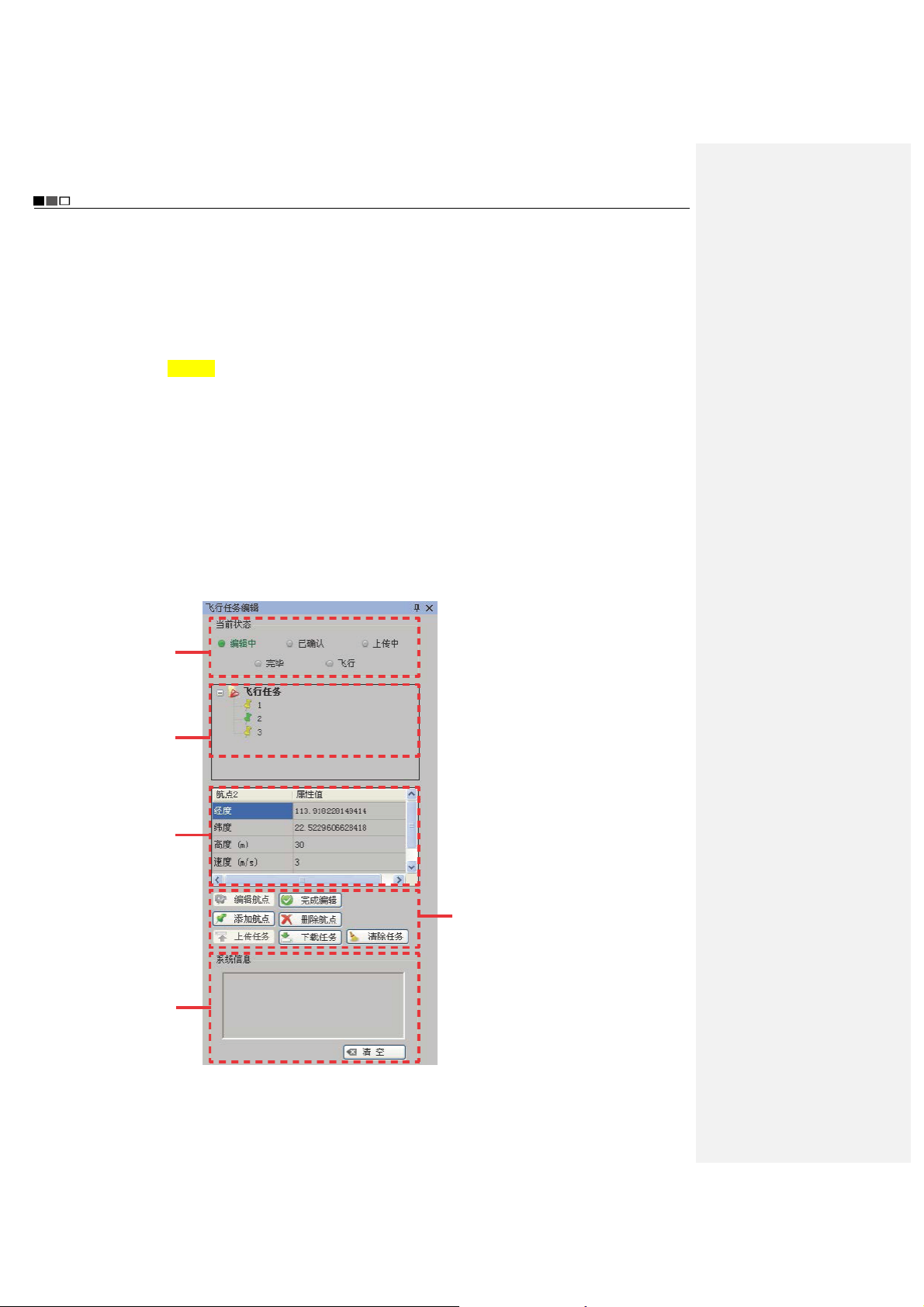
10 Flying Mission Editor
Green indicates the
current status of the
mission.
Waypoint list; the
color of a waypoint
icon changes to green
when it is clicked,
indicating this
waypoint is selected.
ttributes of the
waypoint selected can
be edited: longitude,
latitude, altitude,
speed, and hold time.
Historical information
of system motions is
displayed here. To
clear historical
information, please
click “Clear All”.
z Click “Edit” to reedit the mission that
has been edited.
z Click “End Edit” to confirm the current
mission; the color of air route
changes to green.
z To add a waypoint, click “Add”, and
double-click the position where you
want to add the waypoint on the map
to add the new waypoint.
z Select the waypoint (the waypoint is
selected when its icon turns green)
you want to delete and click “Delete”
to delete this waypoint.
z Click “Upload” to upload the current
flying mission to the UAV.
z Click “Download” to verify if the
mission is successfully uploaded.
z To delete the mission currently being
edited or to edit a new mission, click
“Clear”.
- 38 -

Unmanned Aircraft System
Professional·Advanced
11 Instruments Display Bar
Altitude indicator Airspeed indicator Attitude indicator Heading indicator
12 Status Bar
Display such information as longitude and latitude of the UAV, number of GPS satellite, and battery level in a
real-time way; search, name and locate map data.
Execute Manual Flying Missions with the Ground Station
Flying missions can also be executed through manual operations with the ground station. The steps are as follows:
Switch to the “Manual Fly” mode
Power up the UAV to receive satellite signals
Connect serial port and send joystick data
Check before take-off
Start up the UAV
Perform manual take-off
Control the flight of the UAV with joysticks
Complete the flying mission
Execute Auto Flying Missions with the Ground Station
An auto flying mission can be executed according to the following steps:
- 39 -

Unmanned Aircraft System
Professional·Advanced
Start the ground station software
Switch to the “Auto Fly” mode
Connect serial port and send joystick data
Power up the UAV to receive satellite signals
Edit the flying mission
Complete mission editing
You can continue to edit a completed
mission, and then click “End Edit”.
Upload the flying mission to the UAV
Download the flying mission for verification
Start up the UAV
Perform auto take-off or manual take-off
Perform “Auto Fly” or “Fly To” a designated
waypoint
The waypoint can be edited midway
for continued flight
Go home / abort mission and go home
Complete the flying mission
One-key auto flying mission can be executed according to the steps below:
- 40 -

Unmanned Aircraft System
Professional·Advanced
Start the ground station software
Switch to the “Auto Fly” mode
Connect serial port and send joystick data
Power up the UAV to receive satellite signals
Edit the flying mission
Complete mission editing
Upload the flying mission to the UAV
Download the flying mission for verification
Make sure the throttle is at the lowest position
Perform one-key auto fly
Make sure the throttle is at the lowest position,
and the switch is turned to manual mode
Shut down the UAV
Notice: The throttle joystick should be pushed to the lowest position before one-key auto fly.
You can continue to edit a completed
mission, and then click “End Edit”.
Use the Ground Station Soft ware
Start the Ground Station GPS Software (hereinafter referred to as the “ground station software”)
Select the map type; please make sure that maps have been downloaded before starting the ground station
software. Double-click to open the ground station software, and the system will ask you to select a map type. Select
the desired map type and click “OK”, and maps will be loaded automatically.
- 41 -

Unmanned Aircraft System
Professional·Advanced
If maps cannot be loaded normally after the ground station software is opened, please restart the software,
connect to the network and try loading again.
Connect Serial Ports
1. Connect serial port COM1 (ground station connects to the communication serial port)
Find [COM1
showing “Serial port opened” will pop up on the screen.
Connect] on the toolbar; please select serial port COM1, and click “Connect”. A dialog box
2. Connect serial port COM2 (ground station connects to the joystick serial port)
The dialog box of “Joystick Data” (as shown below) will pop up through ->. Menu ->. Tool ->. Joystick Data.
Select serial port COM2 and click “Connect” to connect the joysticks which are used to control the UAV. ->.
Check “Send Joystick Data”; the progress bars will have corresponding indications when the joysticks are
turned..
In case of any error in connection of serial ports, click “Close” on the toolbar and carry out reconnection.
Joystick Calibration:
After connecting serial port COM2, you can calibrate the joysticks according to the following steps. The
calibration function is mainly used to adjust the maximum, minimal and median values of the joysticks.
- 42 -

Unmanned Aircraft System
Professional·Advanced
1) Click “Calibration”.
2) Rotate the left and right joysticks by 360° until the progress bars of 4 channels pulsate.
3) Push the left and right joysticks, and observe whether there is corresponding pulsation on the progress bar of
each channel.
4) If the calibration is inaccurate, please repeat the above steps.
Important:
1. After successful connection of serial port COM2, the UAV can be manually controlled with the ground station
joysticks after the manual fly mode is switched to.
2. When the remote control is used to control the UAV, please make sure that the option of “Send Joystick Data” in
the ground station software is not checked before take-off; when the ground station joysticks are used to control the
UAV, please make sure that the remote control is in the OFF state before take-off.
3. For joystick calibration, please uncheck “Send Joystick Data”, in order to avoid unpredictable consequences
caused by accidental take-off of the UAV.
3. Connect serial port COM3 (auto tracking antenna connection serial port)
Select COM3 [Antenna:
Connect]; click “Connect”, and the dialog box showing “Serial port
opened” will pop up on the screen.
- 43 -

Unmanned Aircraft System
Professional·Advanced
Power up the UAV to Receive Satellite Signals
After the UAV is powered up, you can view the information received from the UAV on the status bar of the
ground station software, such as voltage, attitude, altitude, and number of GPS satellite. The flying mission can
be edited only when the number of GPS satellite is greater than or equal to 6.
Edit Flying Mission
1. Positioning
Method 1: Add the map location information to the list according to the following steps:
1. Input place name
2. Click “Search”
to load the map.
3. Click “Add” to save the
map data of the current view
and add them to the list.
After successful adding, you can select an added address from the list; the map will automatically locate to this
address after the “Positioning” button is clicked.
Method 2: When the number of GPS satellite is greater than or equal to 6, you can directly click “Display Track”; at
this moment, the map will locate to the current position of the UAV.
- After the ground station software is started, the default position displayed on the map is the last added position.
- As to undesired positioning information, you can also delete it by clicking “Delete” after selecting the location
name.
- The ground station software has the offline positioning function.
1. Maps of Google Satellite and Google Earth for the same area are not universal; please add maps
separately.
2. To use the offline positioning function, please download and back up maps in advance.
2. Add Waypoint
- 44 -

Unmanned Aircraft System
Professional·Advanced
Method 1: Directly double-click the position where you want to add a waypoint on the map to add a waypoint..
Method 2: Click [Add Waypoint] in the Flying Mission Editor, and then click the position where you want to add a
waypoint on the map to add a waypoint.
It is better to add the first waypoint near home point to prevent the UAV from colliding with obstacles due to
excessive obliquity of the UAV route during its ascending.
Add all the desired waypoints with the same method.
After adding the waypoints, you can view the following information of waypoints on the map:
Air route
Horizontal projection
distance between two
waypoints
Index number of waypoint
- Color of air route before editing is finished:
Red: Abnormal
White: Normal
Hidden air route: Abnormal
Notice: Only Google Earth hints abnormality in air route altitude; Google Satellite does not have such hint, so
the air route altitude should be judged by yourself.
3. Edit Waypoint
After adding a new waypoint, you can continue to edit the waypoint.
Notice: After selection, the color of waypoint icon changes to green , indicating this waypoint is selected
and can be edited.
1) Change waypoint position:
Method 1: Use the left mouse button to drag the waypoint to the desired position.
Method 2: Edit longitude and latitude in the Flying Mission Editor. Input the desired longitude and latitude in the
corresponding attribute values, then the waypoint will automatically move to the corresponding position.
- 45 -

Unmanned Aircraft System
Professional·Advanced
2) Change altitude, speed and hold time of waypoint
Input the desired figures in the corresponding attribute values to change the altitude, speed and hold time of the
waypoint.
Notice: To edit the position and altitude of a waypoint, please make sure that altitudes of all waypoints are
applicable for the current terrain. Please see the description in the section of “Add Waypoint” for details.
Finish Mission Editing
Click [End Edit] in the Flying Mission Editor to finish flying mission editing, and all waypoint projection lines
change to green:
Upload Mission
After finishing waypoint editing, click [Upload] to upload the current flying mission to the UAV.
Download Mission
After the mission is successfully uploaded, click [Download] to verify if the mission uploaded is correct; the
following dialog box will pop up after “Download” is clicked:
Select “Yes” to save the current flying mission; select “No” to exit without saving.
Save Flying Mission
- 46 -

Unmanned Aircraft System
Professional·Advanced
After finishing flying mission editing, you can save this flying mission according to the following steps:
1) You can save the currently edited flying mission through Menu -> File -> Save Mission, or the button
on
the Taskbar. The following dialog box will pop up in the ground station software:
2) After “Save” is clicked, the ground station software will automatically save the information of the current flying
mission (including track, waypoint altitude, speed, hold time, etc.).
Flying missions edited with Google Earth are in .KML files; flying missions edited with Google Satellite are
in .XML files.
To call a saved flying mission, please follow the steps below:
1) Load the local-stored flying missions through Menu -> File -> Load Mission. The following dialog box will pop up
in the ground station software:
2) Select the desired flying mission, click “Open” and the ground station software will automatically load the
information of the selected flying mission.
After successful loading of the mission, you shall perform steps in 5, 6 and 7 in the ground station control
software before the UAV can execute the loaded flying mission.
Start the UAV
- 47 -

Unmanned Aircraft System
Professional·Advanced
1) After successful connection of the ground station to joystick serial port COM2, check the option of “Send
Joystick Data”.
2) Switch to the manual fly mode.
3) For the startup method, please see the description in the section of “Start the UAV with the Remote Control”.
1) During outdoor flight, please make sure that the numeric value on the GPS signal strength indicator is
greater than or equal to 6.
2) Check if the indications of the heading indicator and the attitude indicator are consistent with the current
status of the UAV; in case of any inconsistence, please contact us immediately.
Display Track / Clear Track
1) After starting the UAV, click “Display Track” to display the real-time flight track of the UAV during its flying along
the air route (Fig. 1); if “Display Track” is not clicked, the real-time flight track of the UAV will not be displayed
(Fig. 2).
2) When “Clear Track” is clicked after track is displayed, the current real-time flight track of the UAV will be cleared
(Fig. 2).
(Fig. 1) (Fig. 2)
View Locking/Switching Function
After track display, the map interface will automatically enter the view locking state. If [Lock View] is clicked, the
view will be unlocked and you then can move the map. Click this button again to lock up the view.
In the view locking mode, the map view will move as the position of the UAV moves; in the view unlocking
mode, the map view has no change.
Auto Take-off
1) Before take-off, first make sure that the requirements on auto take-off are satisfied. See the instructions in the
section of “Safety Precautions” for details. Auto take-off can be executed only when the requirements are
satisfied.
2) Connect the ground station to serial port COM2, and check “Send Joystick Data”; push the throttle joystick to
the lowest position.
3) Click [Auto Take-off] on the toolbar; the UAV will hover after automatically ascending to an altitude of about
20m.
Auto Fly / Fly to
1) Auto Fly
- 48 -
Unmanned Aircraft System
Professional·Advanced
Click [Auto Fly], and the UAV will automatically fly along the preset air route; the aircraft will hover after reaching
the last waypoint.
2) Fly to
Select the waypoint you want to fly to in the Flying Mission Editor (the color of the selected waypoint is green);
then click [Fly to] on the toolbar, and the UAV will fly to this waypoint; after reaching this waypoint, the aircraft
will hover.
Only one target waypoint can be added every time.
3) Edit Flying Mission in the Air
You can continue to edit the flying mission after the UAV enters the hover state. The following operations can be
realized:
a. Continue to edit the flying mission; after clicking [Edit], you can continue to add waypoints and edit waypoint
information; click [End Edit] after editing is completed (at this moment, it is not needed to clear the flying mission;
you can directly upload the current mission to overwrite the existing mission in the UAV). Click [Download] to
ensure that the mission is correct and then execute the action of [Auto Fly].
b. The action of [Fly to] can be executed, as shown in Step 2 (at this moment, missions saved in the UAV still exist).
c. Click [Clear] to clear the flying missions in the UAV and the content of missions shown on the map; at this
moment, if [Auto Fly] is clicked, the UAV will stay in the hover state.
Before the UAV executes the “Auto Fly” command, please first download the mission to verify if the flying
mission uploaded to the UAV is correct.
Go Home
If [Go Home] is clicked during flight or after the UAV enters the hover state, the UAV will automatically return and
hover over the take-off position.
The altitude of the homeward course is the altitude of the last waypoint.
Auto Landing
Click [Auto Landing] after the UAV returns, and the UAV will automatically land to the take-off position.
1) There might be minor difference between the landing position and the take-off position.
2) To avoid unpredictable consequences, please do not randomly click “Auto Landing” in the course of flight.
3) To close the ground station, please first shut it down normally and then turn off the main power switch.
One-key Auto Fly
Before take-off, please make sure all requirements for one-key auto fly are satisfied (the throttle is at the lowest
position; the manual/auto fly switch is turned to the auto mode; at least one waypoint is uploaded). Please see
the section of “Precautions”. One-key auto fly can be executed only when all requirements are satisfied.
Place the UAV on a horizontal surface (do not place it on a sloped ground for take-off). Only after adding
waypoints to maps in the ground station software, uploading waypoints and downloading waypoints for
verification will the “One-key Auto Fly” button light up and become effective. Click the “One-key Auto Fly”
button on the toolbar; the UAV will finish the entire flying mission, including starting the UAV, auto take-off,
routed flight, going home and landing.
Notice!
1) Click the “One-key Auto Fly” button on the toolbar only after the requirements for one-key auto fly are
satisfied. Otherwise, the UAV will not execute the command.
2) In order to avoid unnecessary troubles, the UAV should be placed on a horizontal surface for take-off.
3) Always observe the state of the UAV during its landing so that the UAV can be controlled manually in a
- 49 -

Unmanned Aircraft System
Professional·Advanced
timely manner in case of any abnormality in this process.
Functions of Video Capture Window in the Ground Station Software
The UAV starts automatic video recording after startup; enter the tab of Video Capture Window of the ground station;
Click [Preview]; the window will display the real-time video sent back by the UAV.
1 Local Video Recording
Click “Local Video Recording” on the toolbar to start recording; after recording is finished, click [Stop] to end
recording and save the video file to the ground station computer. The system will automatically pop up a dialog
box indicating the save path of the video file:
2 Screenshot
Click [Screenshot] on the toolbar to capture the current screen and save the screenshot file to the ground
station computer; the system will automatically pop up a dialog box indicating the image save path:
- 50 -

Unmanned Aircraft System
Professional·Advanced
3 Zoom in / Zoom out
Click “Zoom in” / “Zoom out” to adjust the focal length of the airborne camera.
4 Airborne Video Recording
Click [Airborne Video Recording] on the toolbar to start video recording of the airborne camera; during recording,
the button will remain selected; click the button again to stop recording and it will bounce up.
5 Airborne Photo Shooting
1) Click [Airborne Photo Shooting] on the toolbar to control the camera to take photos.
2) Click [Airborne Photo Shooting] during video recording to realize the snapshot function.
Notice: The functions of zoom in, zoom out, airborne video recording and airborne photo shooting can also
be realized via corresponding buttons on the ground station panel.
6 Video Setting
Parameters of the UAV camera can be set:
7 Photo Setting
Resolution
View Angle
Bit Rate
- 51 -

Unmanned Aircraft System
Professional·Advanced
Image Size
Shot Mode
Continuous Shot Mode
8 Camera Settings
TV-out Format
Metering Mode
- 52 -
Only PAL can be selected
z Average Metering: use this mode when
the luminance difference between the
photograph subject and the background
is relatively slight and steady.
z Central Area Metering: It is the default
mode, applying to scenes when there is
certain luminance difference between
the photograph background and the
subject or the photograph subject
relatively accords with the background.
z Central Spot Metering: It applies to
small-sized subject under extremely
bright or dark background.

Formatting
Unmanned Aircraft System
Professional·Advanced
The airborne camera memory can be
formatted to remove all files in it. Make sure
you do not need the data before formatting!
Recover Factory Setting
This operation will restore all settings of this
system to the factory settings.
Time Setting Set the system time.
No matter whether “Loop Record” is ON or
OFF, recording is saved as a segment file
Loop Record
by each 10 min. When “Loop Record” is
ON, if the space of the memory card is not
enough, the first segment of recording file
will be overwritten automatically.
Time Display
Show or hide time display.
9 Load Setting
Click [Load Setting] on the toolbar to load the current settings of the airborne camera.
- 53 -

Unmanned Aircraft System
Professional·Advanced
10 Save Setting
Click [Save Setting] on the toolbar to save the current settings of the airborne camera.
Important: Settings will take effect only when [Save Setting] is clicked after a setting is modified.
Map Backup
The ground station system adopts the data platforms of Google Earth and Google Satellite. During map browsing,
the system will automatically save the data of browsed maps to the system so that you can view the browsed maps
offline. However, the map storage capacity of Google Earth is limited (the maximum capacity of Google Earth is 2G
and that of Google Maps is 1G). When the capacity of browsed map data exceeds this limit, the old map data will be
lost.
In addition, data loss may be caused by misoperation, which will result in the failure of access to Google Earth data
platform after the ground station system is opened.
To avoid loss of map data, data backup software is provided in the Ubuntu operating system. This software provides
the following three functions:
1 Save map data; during use of the ground station, the user can save the map data according to area partition
and date.
Note: The data backup file should not exceed the map capacity limit (Google Earth: 2G; Google Maps: 1G).
2 Restore map data; in case maps cannot be loaded due to data loss during use, if access to Internet is also not
available, the user can enter this software to restore map data.
3 Delete: Delete undesired backup data.
Important: Before use of map backup, first open the ground station GS software in the Windows system, and
make sure that maps of Google Satellite and Google Earth have been downloaded and can be used.
The backup operation steps are as follows:
1 Start up and select to enter the Ubuntu system (see the following figure):
After opening the ground station system, select to enter the Ubuntu system in the “Select System” menu:
- 54 -

Unmanned Aircraft System
Professional·Advanced
Double-click to open the Google Maps Data Management software:
2 Backup operation:
- First, open the ground station GS software in the Windows system, and make sure that maps of Google
Satellite and Google Earth have been downloaded and can be used.
- Then, go back to the Ubuntu system to open the Google Maps Data Management software.
- Click “Data Backup”, enter the backup name, and click “OK” to save the last map data browsed in the ground
station software. See the following figure:
The system will pop up a dialog box indicating successful backup:
Generate backup data:
3 Data Recovery
Select the map data to be recovered (the selected data are in orange background), and click “Data Recovery”;
the system will pop up a dialog box indicating successful recovery:
- 55 -

Unmanned Aircraft System
Professional·Advanced
Before data recovery, please first back up data; otherwise, data recovery cannot be performed.
a) Data Deletion
Delete data that have been backed up; select the backup data you want to deleted, and click “Data Deletion”; the
system will pop up a dialog box indicating successful deletion:
b) Exit from Google Maps Data Management:
Click “Exit” at the top right corner of Google Maps Data Management software to exit the software.
c) Log out of the Ubuntu system
Click
moment.
at the top right corner of the screen to select “Shutdown”. Map backup editing is completed at this
Auto Tracking Antenna
The auto tracking antenna enables the user to accurately know the longitude and latitude information of the UAV,
precisely locate the position of the UAV, and carry out automatic tracking in a real-time way.
Guide for Components of the Auto Tracking Antenna
- 56 -

Unmanned Aircraft System
Professional·Advanced
No. Type Quantity Function
1 Panel antenna 1 Receives radio and video signals
2 Video signal port 2 Receives video signals
3 Radio signal port 1 Receives radio signals
4 Indicator (red) 1
5 Indicator (blue) 1
6 Communication cable port 1
Radio antenna extension
7
8
9 PTZ 1 Fix the console
10 Power switch 1 Execute the power-on/off action
11 Tripod 1 Support the console and antennas
cable port
Video antenna extension
cable port
1 Sends radio signals received to the ground station
2 Sends video signals received to the ground station
The red indicator light turns on when power supply is
connected
The blue indicator light is always on after initialization is
finished and blinks during normal working
1. Receives video signals
2. Receives radio UART signals
3. The ground station sends commands via USB to the
steering engine to control rotation of the antenna
Install the Tripod
- 57 -
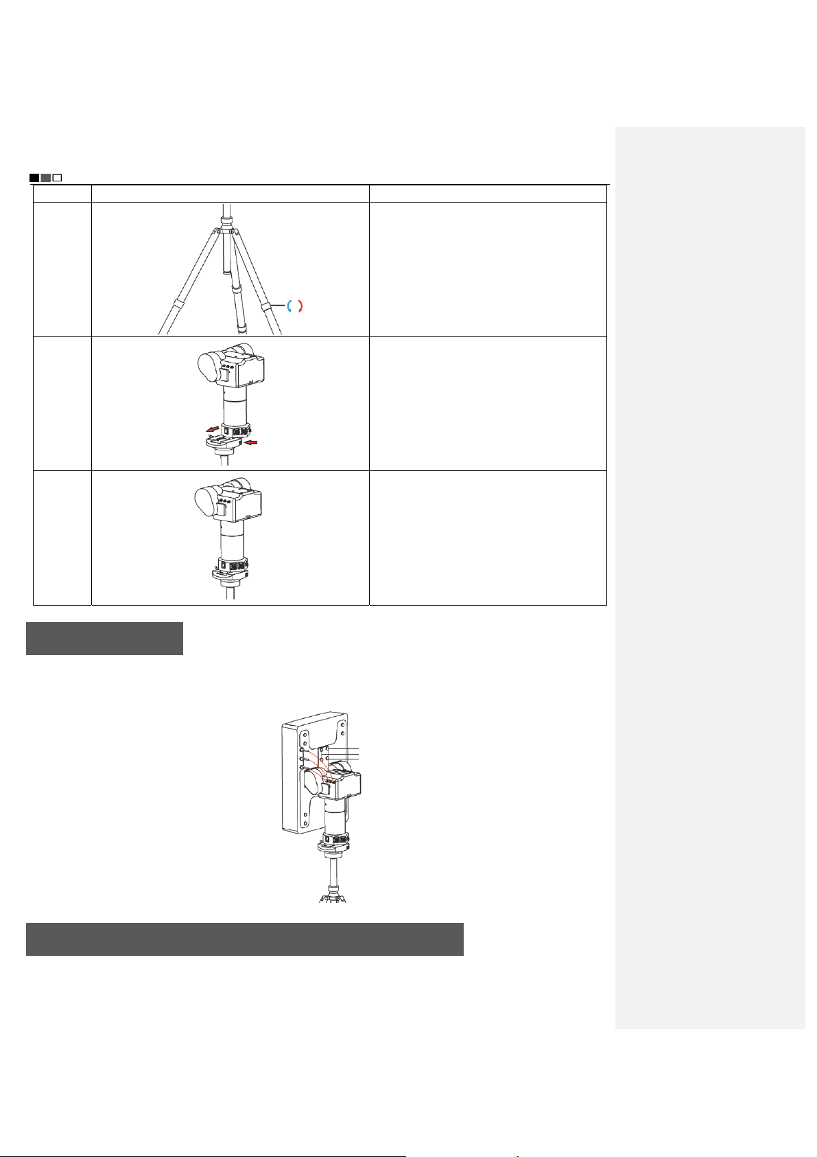
Unmanned Aircraft System
Professional·Advanced
Step Illustration Description
Step 1
Step 2
Step 3
Unfold the three legs of the tripod; turn the
knob clockwise; lengthen each leg to a proper
position and then counter-clockwise tighten
the knob.
Press the button on the right side to push the
auto tracking device into the PTZ groove in
the direction of arrow.
Tighten the knob on the left side to fix it.
Install the Antenna
Use the wrench to install 4pcs of screw by aligning them with the corresponding holes in the panel antenna, so as to
fix it to the auto tracking antenna, as shown in the figure below. Then, connect the 3pcs of antenna extension cable
on the panel antenna to the auto tracking device according to the following figure (shown in red lines).
Screws
Connect the Radio and Video Antenna Extension Cables
- 58 -

Unmanned Aircraft System
Professional·Advanced
Step Illustration Description
Step 1 Insert the radio antenna extension
cable and the video antenna extension
Video antenna
extension cables
Radio antenna
extension cable
cables respectively into the RADIO,
VIDEO-1 and VIDEO-2 ports on the
auto tracking antenna according to the
direction shown in the figure, and
tighten them clockwise.
Step 2 Insert the radio antenna extension
Insert the
video
antenna
extension
cable
Insert the
video
antenna
extension
cable
Insert the
radio
antenna
cable and the video antenna extension
cables respectively into the RADIO,
VIDEO-1 and VIDEO-2 ports on the
ground station according to the
direction shown in the figure, and
tighten them clockwise.
extension
cable
Connect the Communication Cable
Insert the communication cable according to the direction shown in the figure below, and insert the other end to the
AUTO ANTENNA port on the ground station.
Insert the other
end of the
Insert the
communication
cable here
communication
cable
Start up the Auto Tracking Antenna
First, turn on the power switch of the ground station; then, turn on the power switch of the auto tracking antenna. The
- 59 -

Unmanned Aircraft System
Professional·Advanced
red power indicator turns on, and the antenna begins initialization; the initialization is finished when the antenna
faces south. As to the method for connecting the auto tracking antenna to the ground station software, please see
the section of “Use the Ground Station Software — Auto Tracking Antenna Connection Serial Port” on Page 43.
Notice: 1. When using the auto tracking antenna, please keep away from areas subjected to intense
electromagnetic interference.
2. When connecting the auto tracking antenna to the ground station software, please first turn on the
power switch of the auto tracking antenna and then open the ground station software.
Shut Down the Auto Tracking Antenna
First, close the ground station GS software; then, turn off the power switch of the auto tracking antenna, and
disconnect the communication cable, radio antenna extension cable and video antenna extension cables.
Warning: When disconnecting the communication cable of the auto tracking antenna, please first pull the aviation
plug shell outward, and then pull out the plug.
Video Files
After startup, the UAV will automatically enter the video recording state. The user can preview the video on the
screens of the remote control and the ground station. When the UAV is shut down, recording will be stopped and
video files saved automatically. Using a USB data cable, you can copy the video files in the UAV to a PC for
playback. The real-time videos sent back by the UAV can be saved to the memory of the remote control by pressing
the “Local Recording” button of the remote control or the ground station. For detailed operation methods, please
refer to the section of “Description of Buttons” of the remote control and the ground station.
批注[e6]:原稿:天线面朝南
方,初始化完毕。
是指天线面朝南方时,初始化完毕
吗?
批注[e7]:原稿:P41
译稿中该部分是在 43 页上
Specification
Description Specification
Fly mode Manual remote control, autonomous hover, autonomous route
No-load take-off weight ≤7.8kg (with battery)
Load capacity ≤4.5kg
Endurance time 40min (20,000mAh battery)
30min (15,000mAh battery)
Maximum cruising speed 15m/s (not suggested)
Maximum remote control range 10km
Maximum flying range 20km
Flight altitude (relative altitude) Max. 3,000m
Climbing speed ≥8m/s
Normal take-off/landing wind speed Below Level 6
Working temperature -10°C ~ +50°C
Working humidity 0% ~ 95%RH
Storage temperature -20°C ~ +60°C
Airborne camera HD camera with two-axis PTZ
- 60 -

Unmanned Aircraft System
Professional·Advanced
Troubleshooting
Before test flight, please read the “Operation Instruction” first. If normal take-off fails, please perform troubleshooting
according to the table below. If the problem still exists, please contact us immediately. To avoid unnecessary loss,
please do not operate blindly!
Symptom Solution
Self-checking of the UAV fails after it is powered up (the
buzzer beeps all the time)
Speeds of the four motors are obviously inconsistent
with each other after startup (some run fast, while some
run slowly)
The UAV cannot be started after successful
self-checking
The state of navigation lights is abnormal; the normal
state is green in the front and red in the rear
The remote control and the ground station shows
abnormality of flight attitude and compass (e.g., 360°
rotation)
The UAV fails to execute auto take-off and one-key
auto fly
The UAV cannot be controlled manually when it goes
home or lands upon low battery
The UAV inclines or rotates during one-key auto fly Power off the UAV and then power it on again
Normal take-off fails when the throttle lever is pushed
forward after the UAV is started
(1) Check if the removable arms are properly installed
(1) Make sure the UAV is placed on a flat ground before
self-checking
(2) Calibrate the UAV
Check the manual/auto switches of the remote control
and the ground station to make sure that they are in the
manual state
Confirm whether the frame arms are properly installed
(frame arm A1 shall correspond to body A1, and so on
and so forth)
Calibrate the compass, accelerometer and gyroscope
according to the instruction manual
Confirm whether the manual/auto switch of the remote
control or ground station is in auto state
Make sure that the manual/auto switch is switched 2-4
times when the throttle joystick is at the middle position.
(1) Check the four propellers of the UAV to see if they
are installed properly as required in the Instruction
Manual
(2) Check the power battery of the UAV to make sure the
battery level is high enough.
Protection Mechanism
1. During flying in the manual mode, when it is beyond the operating range, the UAV will enter the protection mode,
and automatically fly back to the take-off position and land.
2. During flying in the manual/auto mode, when the remote control or the ground station is powered off, the UAV
will enter the protection mode, and automatically fly back to the take-off position and land.
3. In case of Level 2 alarm for low battery, the UAV will enter the protection mode; at this moment, the UAV will
vertically descend to the ground (in case of an emergency, in the auto fly mode, you can switch to the manual
mode to control landing manually; in the manual fly mode, switch to the auto mode and then to the manual mode
to realize manual control of landing).
- 61 -

Popular in European,
Patented
Technologies
National Hi-tech
Enterprise
Guangdong Famous
Trademark
Shenzhen Top
Brand
American and Asian
Markets with
Self-owned AEE Brand
Please read this Manual carefully before use, and keep it handy for future reference.

FCC Information and Copyright
This equipment has been tested and found to comply with the limits for a Class B digital device,
pursuant to part 15 of the FCC Rules.
These limits are designed to provide reasonable protection against harmful interference in a residential
installation. This equipment generates,
uses and can radiate radio frequency energy and, if not installed and used in accordance with the
instructions, may cause harmful interference
to radio communications. However, there is no guarantee that interference will not occur in a particular
installation. If this equipment does
cause harmful interference to radio or televisi on reception, which can be determined by turning the
equipment off and on, the user is
encouraged to try to correct the interference by one or more of the following measures:
—Reorient or relocate the receiving antenna.
—Increase the separation between the equipment and receiver.
—Connect the equipment into an outlet on a circuit different from that to which the receiver is
connected.
—Consult the dealer or an experienced radio/TV technician for help.
15.19 Labelling requirements.
This device complies with part 15 of the FCC Rules. Operation is subject to the
following two conditions:
(1)This device may not cause harmful interference, and
(2) this device must accept any interference received, including interference that may
cause undesired operation.
changes or modifications not expressly approved by the party responsible for compliance could
void the user's authority to operate the equipment.

Created in China
Made in Shenzhen
Add.: AEE Hi-Tech Park, Tangtou Intersection, Songbai Road, Shiyan Sub-district, Bao’an District, Shenzhen
Tel.: 0755-29518999 Fax: 0755-27358999
 Loading...