

AEE Unmanned Aircraft System
Professional Leading
Firmware upgrade
Under the functional option parameters, this function is limited to factory upgrades and users
do not need to operate. As shown below:
Altitude hold mode
Camera parameters
Drone settings
Remote control
settings
Map management
Firmware upgrade
Version information
Image transmission
information
Insert U
disk
Select file
Insert U disk
Refresh
Upgrading
Completed
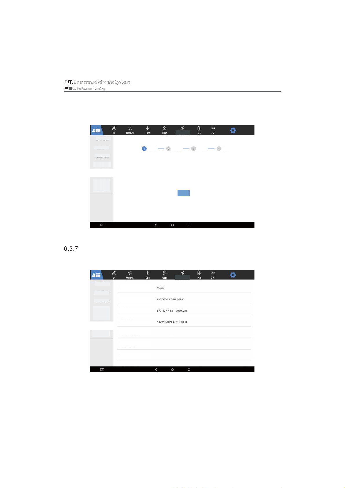
Version information
Under the functional parameter options, you can view the software version information
related to the aircraft, remote control, etc. As shown below:
Camera parameters
Drone settings
Remote control
settings
Map management
Firmware upgrade
Version information
Image transmission
information
Altitude hold mode
App version
Drone version
Flight controller version
Remote control version
Air data transmission version
Ground data transmission version
Air image transmission version
- 18 -
AEE Unmanned Aircraft System
Professional Leading
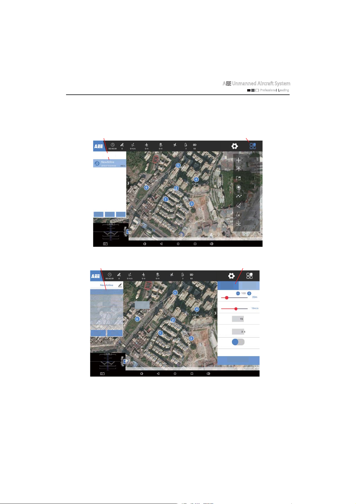
Map display and route function
Click the map screen to enter the map planning page, flight mission functions such as related route
mission tasks, waypoint parameter editing, route operation and map download can be set, as shown below
Route mission
Route list
Create+
Delete
Edit
Waypoint editing
Waypoint 1
Waypoint 2
Waypoint 3
Waypoint 4
Waypoint 5
Waypoint 6
Delete
Save
Not connected
Not connected
Waypoint longitude:0.0
Waypoint latitude:0.0
Waypoint parameter setting
Waypoint longitude:0.0
Waypoint latitude:0.0
Residence
Route function list
Edit the route
Upload routes
Export routes
Waypoint
selection
Execute routes
Clear flight
paths
Unlock
Download
maps
General settings
Flight altitude
Flight speed
Gimbal
pitch
time
Video
Single waypoint
0
- 19 -
Apply to all waypoints
A
AEE Unmanned Aircraft System
Professional Leading
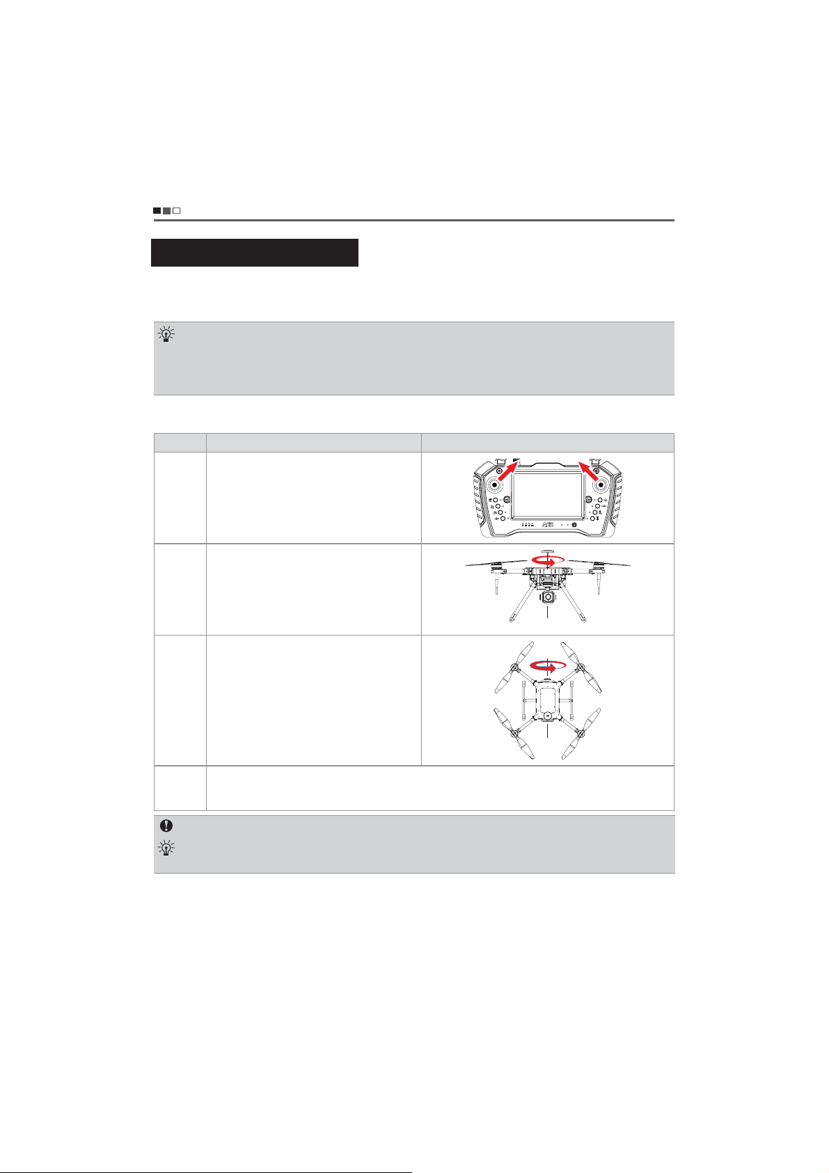
Calibration of the aircraft
Calibration of the compass
Please calibrate the compass according to the indication of the aircraft status indicator. Calibration
precautions are as follows:
Calibration steps
Please select an open space to start up the remote control and the aircraft, ensure that the equipment is normal, and calibrate the
compass according to the following steps.
Steps Operation methods Illustration
Step 1
1. Do not calibrate near areas of strong magnetic field or large pieces of metal, such as magnetic mines, parking lots and
building areas with underground steel bars.
2. Do not carry any ferromagnetic substances, such as mobile phones, during calibration.
After the compass is successfully calibrated, when the aircraft is placed back on the ground, if disturbed by the magnetic
3.
field, the processing method will be displayed. Please follow the displayed processing method for corresponding operation.
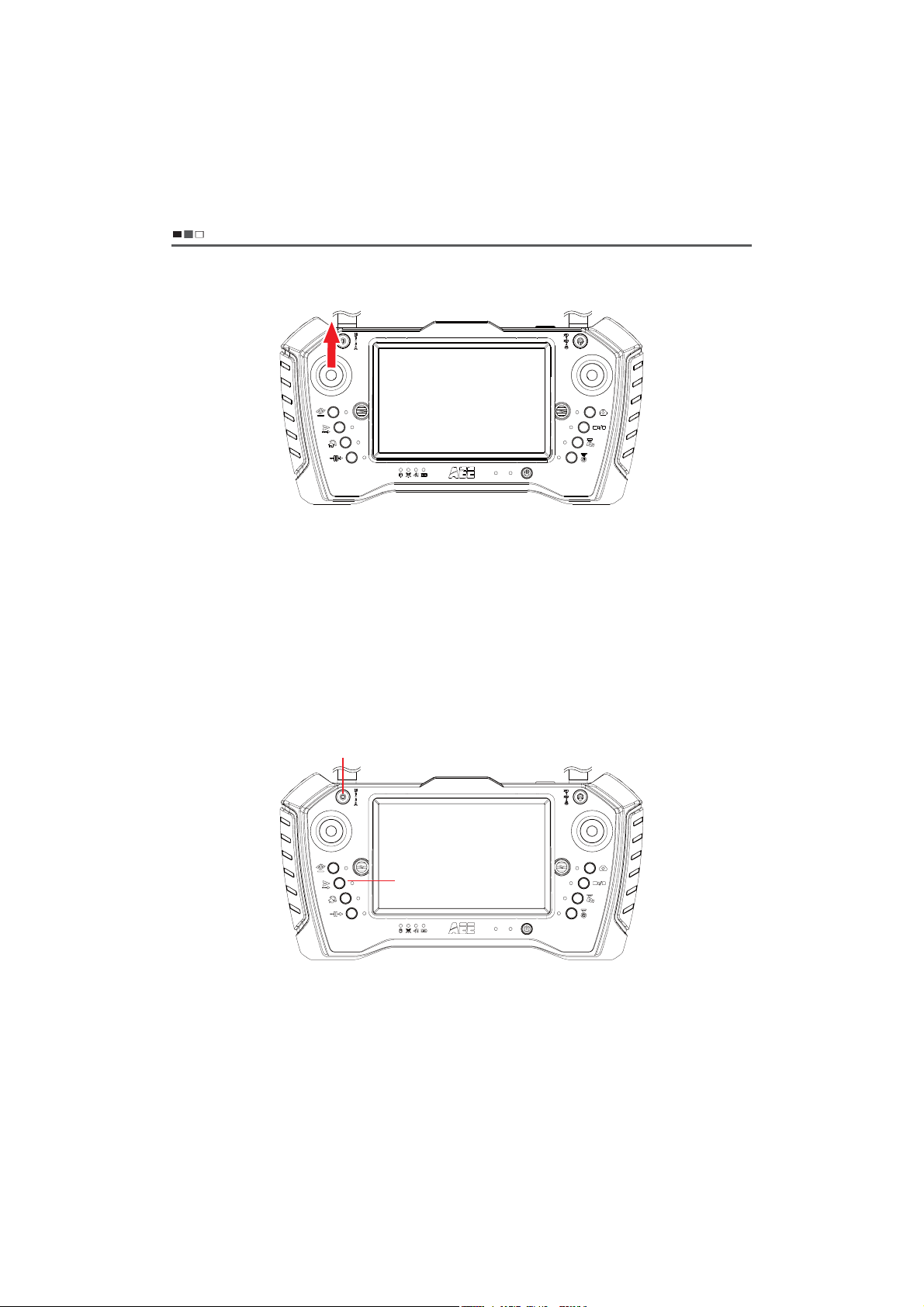
Turn the left joystick of the remote control to the
upper right corner and the right joystick to the upper
left corner (this action needs to be held for 3S to 5S),
as shown on the right.
At this time, the aircraft status indicator flashes slowly
in yellow, indicating that the compass calibration
procedure has started.
Step 2
Step 3
Step 4
Rotate the aircraft horizontally by 360° to the aircraft
status indicator flashing slowly in green, as shown on
the right.
Keep the aircraft nose up, rotate the aircraft
horizontally by 360° until the rear navigation light is
kept on (the red light will be kept on when the takeoff condition is not met; the green light will be kept on
when the take-off condition is met).
After the calibration, if the aircraft status indicator shows alternate red and yellow flashing, it indicates that the
calibration fails. Please recalibrate the compass according to step 1 to step 3.
Note: After the calibration, if the aircraft status indicator still shows alternate red and yellow flashing, it indicates that there is
interference. Please change the calibration site. If there is an uncalibrated compass prompt on the interface before the aircraft
takes off, you need to calibrate the compass. After the successful calibration, the prompt will disappear automatically.`
Situations requiring recalibration
(1) The compass data is abnormal, and the aircraft status indicator shows alternate red and
yellow flashing.
(2) The flight site is far away from the site where the compass was calibrated last time.
A
AEE Unmanned Aircraft System
Professional Leading
(3) There is a serious drift during flight, or the aerial vehicle fails to fly in a straight line.。
Flight control of the aircraft
Take-off preparation
1. Check the battery level of the drone and the remote control, and charge them if the battery is low.
2. Check whether the propeller of the drone is tight and ensure that the blades are in the unfolded state.
3. Make sure that the remote control mode switch is in the middle position and the remote control is displayed as
"fixed point mode".
Please check whether the compass data and attitude data are correct before flight. (Compass: when the drone is
4.
still, the compass deviation angle of the remote control is within +/-2° and does not change. Attitude: raise one
side arm of the drone, and the remote control attitude display can change accordingly.); perform servo check,
and calibrate the joystick if any abnormality is found.
Place the drone to the take-off point (with the power switched off), and ensure that the take-off point takes the
5.
drone as the center of the circle for safety, without obstacles within a radius of 10 meters.
Turn on the power switch of the drone. The drone is able to take off when the rear arm navigation light of the
6.
drone is kept on in green and the remote control interface shows fixed point mode.
7. Try to avoid starting two drones at close range simultaneously to prevent accidents.
Ensure that both the video antenna and the radio antenna are installed correctly before the flight, to avoid
8.
affecting the flight and video receiving distance or causing damage to the transmitting module inside the drone
and remote controller.
Start the drone
Place the aircraft on an open horizontal surface, connect the power, turn the power switch to ON, and start up the aircraft
1.
to the satellite positioning state.(The tail light of the aircraft is red during the satellite positioning, and will be green after
the successful satellite positioning);
Press the remote control for 1S, then press and hold the power button to turn it on. The remote control will automatically
2.
enter the GS software and the interface. Click to enter the device, and after the enterance, the remote control will display
the status of the aircraft (such as satellite intensity, speed, altitude, distance, latitude and longitude).
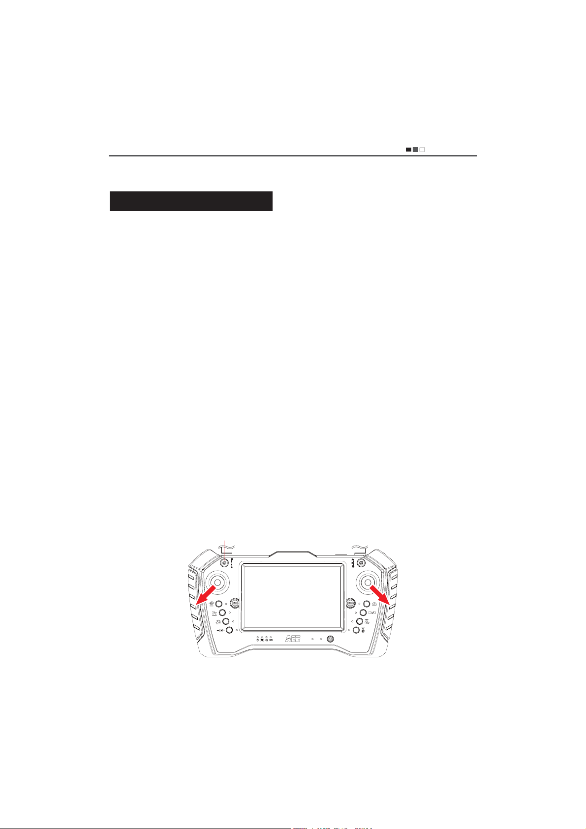
Manual take-off. Under the condition of successful satellite positioning of the aircraft (the tail light of the aircraft is
3.
green), switch the remote control mode to the fixed point mode (middle position), make the remote control joystick
perform the "down splayed" operation. Then the aircraft is unlocked, and the blades start rotating. When it enters into
the idle state, release the joystick to the center, make the left joystick slowly push the throttle, then the motor of the
aircraft accelerates and the aircraft will slowly rise. As shown below:
Middle position: fixed point mode
A
AEE Unmanned Aircraft System
Professional Leading
Automatic take-off. Under the condition of successful satellite positioning of the aircraft (the tail light of the
4.
aircraft is green), switch the remote control mode to the fixed point mode (middle position), perform the one
button take-off function of the remote control, and click "Yes" when the remote control gives the prompt about
whether to perform one button take-off, and the aircraft will unlock automatically and take off vertically to 10m
(by default). As shown below:
Push the throttle to make the aircraft rise
Middle position: fixed point mode
One button full-automatic route flight

Direction control
AEE Unmanned Aircraft System
Professional Leading
The drone direction is defined as follows:
A
Front
(Nose)
Left
Rear
(Tail)
Right
Details are shown in the following table:
Joystick Drone attitude Illustration
Altitude and heading remain
unchanged
Left joystick centered
Left joystick
forward, right
joystick in situ
When the left joystick is centered,
the altitude and heading of the
aircraft remain unchanged
Upward
When the motor speed increases,
the propeller speed becomes
faster; the bigger the joystick's
amplitude is, the faster the
climbing speed will be.
Horizontal line
Horizontal line
Left joystick
backward, right
joystick in situ
Downward
When the motor speed decreases,
the propeller speed becomes
slower; the bigger the joystick's
amplitude is, the faster the
landing speed will be.
Horizontal line

A
AEE Unmanned Aircraft System
Professional Leading
Left joystick to
right, right joystick
in situ
Left joystick to left,
right joystick in situ
Right joystick centered
Turn the nose right
(Clockwise rotation)
Turn the nose left
(Anticlockwise rotation)
Right joystick centered. When the
number of GPS satellites is ≥ 6,
the position of the aircraft remains
unchanged. When the number of
GPS satellites is <6, the aircraft
position needs to be manually
controlled. The tail light is kept on
in green after the satellite
positioning
Horizontal line
Right joystick
forward, left
joystick in situ
Right joystick
backward, left
joystick in situ
Fly forward
The nose is downward, and the
drone tilts forward and flies in the
direction of the nose. At this point,
push the throttle forward a little to
adjust the flight altitude to make
the drone fly horizontally
Fly backward
The tail is downward, and the drone
tilts backward and flies in the
direction of the tail. At this point,
push the throttle forward a little to
adjust the flight altitude to make the
drone fly horizontally
Fly forward
The nose direction
Horizontal line
Pitching angle
Right view
Fly backward
The tail direction
Horizontal line
Pitching angle
Right view

A
AEE Unmanned Aircraft System
Professional Leading
Roll to the right
Fly to the right
Horizontal line
Right joystick to
right, left joystick
in situ
The drone tilts to the right and
flies to the right.
Tail of the aircraft
Roll to the left
Roll angle
Fly to the left
Horizontal line
The drone tilts to the left
Right joystick to
and flies to the left.
left, left joystick in
situ
The throttle lever of the remote control is the power lever to control the propeller speed, which can control the rise and fall of the
drone. The push of the throttle lever should be gentle to avoid large fluctuations. When the left joystick is centered, the altitude
and heading of the aircraft remain unchanged. The right joystick of the remote control is the direction lever, pushing left means
flying to the left, pushing right means flying to the right, pushing forward means flying forward, and pushing backward means
flying backward.
Roll angle
Tail of the aircraft
Flight mission editing
Route list
Delete
Create+
Edit
Not connected
- 25 -
Waypoint longitude:0.0
Waypoint latitude:0.0
Edit the route
Upload routes
Export routes
Waypoint
selection
Execute routes
Clear flight
paths
Unlock
Download maps

AEE Unmanned Aircraft System
Professional Leading
Delete
Edit routes: enter the route editing mode to display the route list: long press on the map, the waypoint
1 appears, then appears the waypoint 2...to complete the editing. To modify the waypoint, long press
the waypoint to move it;
Upload routes: upload the edited routes to the unmanned aircraft system for flight missions; Waypoint
selection: during the flight, the aircraft can fly to the designated position by selecting the desired
waypoint;
Execute routes: after editing and uploading the route task to the drone, execute the route function, and
then the aircraft will fly according to the edited route planning task;
Clear flight paths: click the function button to clear the flight path of the aircraft on the map; Lock the
heading: click the function button to maintain a certain flight course and display position during the
flight of the aircraft; Download maps: in the case of networking, flight map data can be downloaded
through this function for mission flight; Route list: display all currently saved route tasks;
Create: add a new route editing task; Delete (route) : delete a designated route task; Edit: edit the
waypoint parameters of the selected route; Waypoint: a new waypoint (flight target point) can be
established by short pressing the map position of the display screen; Delete (waypoint) : delete a
designated waypoint planning task information; Save: save all relevant parameters and settings of
waypoints;
General settings: set relevant uniform parameters for all waypoints, such as flight altitude, flight speed,
gimbal pitching, residence time and other relevant parameters of all waypoints;
Single waypoint: set the parameters of single waypoints to meet the different requirements of different
waypoint tasks.
Waypoint 1
Waypoint 2
Waypoint 3
Waypoint 4
Waypoint 5
Waypoint 6
Save
Not connected
Waypoint longitude:0.0
Waypoint latitude:0.0
General settings
Flight altitude
Flight speed
Gimbal
pitch
Residence
time
Video
Apply to all waypoints
Single waypoint
0

EE Unmanned Aircraft System
A
Usage process of GS software route planning task
Start the aircraft and remote control
ī
Aircraft receiving satellite positioning
ī
Go to the GS map page
ī
Load/download map data
ī
+Edit routes
ī
Create route tasks
ī
Edit and save the waypoint parameters
ī
Upload routes
ī
Start the aircraft
ī
Execute routes
ī
Complete route tasks, land and stop the propelle
ī
Shut down the aircraft and remote control
Professional Leading
- 27 -

AEE Unmanned Aircraft System
Professional Leading
Return
One button return. When the aircraft is flying in the air, operate the one button return button on the remote
1.
control, the screen will prompt “whether to return”, and then click “Yes”, the aircraft will fly to a certain
altitude, then return to the top of the take-off point, and finally land to the ground slowly and stop the propeller.
Manual return. Control the drone above the safe position by the remote control, and slowly pull down the
2.
throttle to the drone landing on the ground, then pull the throttle to the lowest position for 3S to 5S, the aircraft
will automatically enter the lock mode and stop the propeller. As shown below:
The throttle is pulled down slowly to the lowest position when the aircraft lands on the ground
Shut down the drone
1. Shut down the drone
Turn the power switch of the drone landing on the ground and stopping the propeller to the OFF position,
then disconnect the power cord between the host and the battery, push the battery compartment lock button to
remove the battery.
2. Shut down the remote control
Double-click the power button of the remote control, and "Shutdown remote control" and "Restart remote
control" will appear in the display screen of the remote control. Select "Shutdown remote control", and then the
remote control will enter the shutdown state.
- 28 -

A
EE Unmanned Aircraft System
Professional Leading
Troubleshooting
Please read the"operation manual" first before the test flight. Make troubleshooting according to the following
methods if the drone fails to take off normally. Please contact us in the first time if you can't solve the problem after
following the methods below. Do not operate blindly to avoid causing unnecessary losses!
Faults Troubleshooting
Difficulty in uploading and downloading
waypoints to aircraft
The airborne camera cannot be selfstabilized after the aircraft is powered on
After the aircraft flies far away, the remote
control image appears stuck or mosaic
Protection mechanism
When flying in the manual mode, the drone will enter the protection mode and automatically return to the take-
1.
off point and land if beyond the operating range.
When flying in the manual/automatic mode, the drone will enter the protection mode and automatically return to
2.
the take-off point and land if the remote control is shut down.
In the state of second-level low power, the drone will enter the protection mode, and the aircraft will descend to
3.
the ground vertically and slowly at the current position. At this time, the attitude and altitude of the aircraft can
still be controlled by remote control. But two points need to be noted:
Ensure that the aircraft and the remote control are properly equipped with
antennas, and that the distance is not too far;
Restart the aircraft
The complicated electromagnetic environment will affect the receiving effect of the
antenna of the remote control. Putting the remote control upright and making the
antenna vertical upward can achieve the best transmission effect of the antenna of
the remote control.
When landing in the state of second-level low-power, the aircraft should be controlled gently as
the battery level is too low.
- When landing in the state of second-level low-power, the middle position of the throttle lever
of the remote control will move downward. At this time, if you want to keep the altitude of the
aircraft unchanged or continue to climb, you need to push the throttle lever upward.
FCC Warning
This device complies with part 15 of the FCC Rules. Operation is subject to the following two conditions:
(1) This device may not cause harmful interference, and (2) this device must accept any interference
received, including interference that may cause undesired operation.
Any Changes or modifications not expressly approved by the party responsible for compliance could void
the user's authority to operate the equipment.
- 29 -

EE Unmanned Aircraft System
A
Professional Leading
4UZK This equipment has been tested and found to comply with the limits for a Class B digital device,
pursuant to part 15 of the FCC Rules. These limits are designed to provide reasonable protection against
harmful interference in a residential installation. This equipment generates uses and can radiate radio
frequency energy and, if not installed and used in accordance with the instructions, may cause harmful
interference to radio communications. However, there is no guarantee that interference will not occur in
a particular installation. If this equipment does cause harmful interference to radio or television reception,
which can be determined by turning the equipment off and on, the user is encouraged to try to correct
the interference by one or more of the following measures:
-Reorient or relocate the receiving antenna.
-Increase the separation between the equipment and receiver.
-Connect the equipment into an outlet on a circuit different from that to which the receiver is
connected.
-Consult the dealer or an experienced radio/TV technician for help.
9VKIOLOI'HYUXVZOUT8GZK9'8OTLUXSGZOUT
This Hand-held ground controller meets the government's requirements for exposure to radio waves.
The guidelines are based on standards that were developed by independent scientific organizations
through periodic and thorough evaluation of scientific studies. The standards include a substantial safety
margin designed to assure the safety of all persons regardless of age or health.
,))8,+^VUY[XK/TLUXSGZOUTGTJ9ZGZKSKTZ
The SAR limit of USA (FCC) is 1.6 W/kg averaged over one gram of tissue. Device types: Hand-held ground
controller (FCC ID: 2AGZGY12001) has also been tested against this SAR limit. The highest SAR value
reported under this standard during product certification for use at the body is 0.337W/kg. the simultaneous
transmission SAR value is 0.337W/kg on the head This device was tested for typical body-worn operations
with the back of the handset kept 0mm from the body. To maintain compliance with FCC RF exposure
requirements, use accessories that maintain a 0mm separation distance between the user's body and the
back of the handset. The use of belt clips, holsters and similar accessories should not contain metallic
components in its assembly. The use of accessories that do not satisfy these requirements may not comply
with FCC RF exposure requirements, and should be avoided.
(UJ_]UXT5VKXGZOUT
This device was tested for typical body-worn operations. To comply with RF exposure requirements, a
minimum separation distance of 0mmmust be maintained between the user’s body and the handset,
including the antenna. Third-party belt-clips, holsters, and similar accessories used by this device should
not contain any metallic components. Body-worn accessories that do not meet these requirements may
not comply with RF exposure requirements and should be avoided. Use only the supplied or an approved
antenna.
- 30 -

EE Unmanned Aircraft System
A
Professional Leading
,))/* '-@->
This equipment complies with FCC radiation exposure limits set forth for an uncontrolled environment.
This equipment should be installed and operated with minimum distance 20cm between the radiator &
your body.
AEE independent brand
Possess multiple patented
technologies
National High-tech
Industry
Guangdong
Famous Trade Mark
Shenzhen Top Brand
sold well in European,
American and Asian
countries
Please read this manual carefully before use and keep it properly for reference.
- 31 -

."%&*/$)*/"
Made in Shenzhen
Address: AEE Hi-tech Park, Shenzhen, China (Songbai Road,
Shiyan Street, Baoan District)
Tel: 0755-2951 8999 Fax: 0755-27358999
 Loading...