

Page 1
A.E.B. INDUSTRIALE s.r.l.
Via Brodolini, 8 - 40056 Crespellano (Bo) - ITALIA
Tel. + 39 051 969870 - Fax. + 39 051 969725
Internet: www.dbtechnologies.com
E-mail: [email protected]
Made in Italy
COD. 420120203 Rev 2.0
Digital Vertical ArrayDigital Vertical Array
T8
MANUALE D’USO - Sezione 1
USER MANUAL - Section 1
BEDIENUNGSANLEITUNG - Abschnitt 1
CARACTERISTIQUES TECHNIQUES - Section 1
Page 2
DESCRIZIONE
®
Il diffusore DVA T8 è equipaggiato con tre amplificatori in classe D della serie DIGIPRO
G2, ad alta efficienza, che permettono di ottenere elevate potenze di uscita con pesi ed
ingombri ridotti. Grazie alla sua bassa potenza dissipata, il raffreddamento del modulo
amplificatore avviene in modo statico, evitando l’uso della ventola.
®
Il circuito di alimentazione dell’amplificatore DIGIPRO G2 è stato progettato per lavorare
in modalità full-range; grazie alla tecnologia SMPS (Switched-Mode Power Supplies) con
PFC (Power Factor Correction) viene garantito il funzionamento a tensioni di
alimentazioni da 100V a 240V, garantendo le stesse prestazioni acustiche anche con
linee di alimentazione fluttuanti e non stabilizzate.
Il modulo amplificatore è in grado di erogare 350W (RMS) per la sezione dei bassi, 175W
(RMS) per la sezione dei medi e 175W (RMS) per la sezione degli alti.
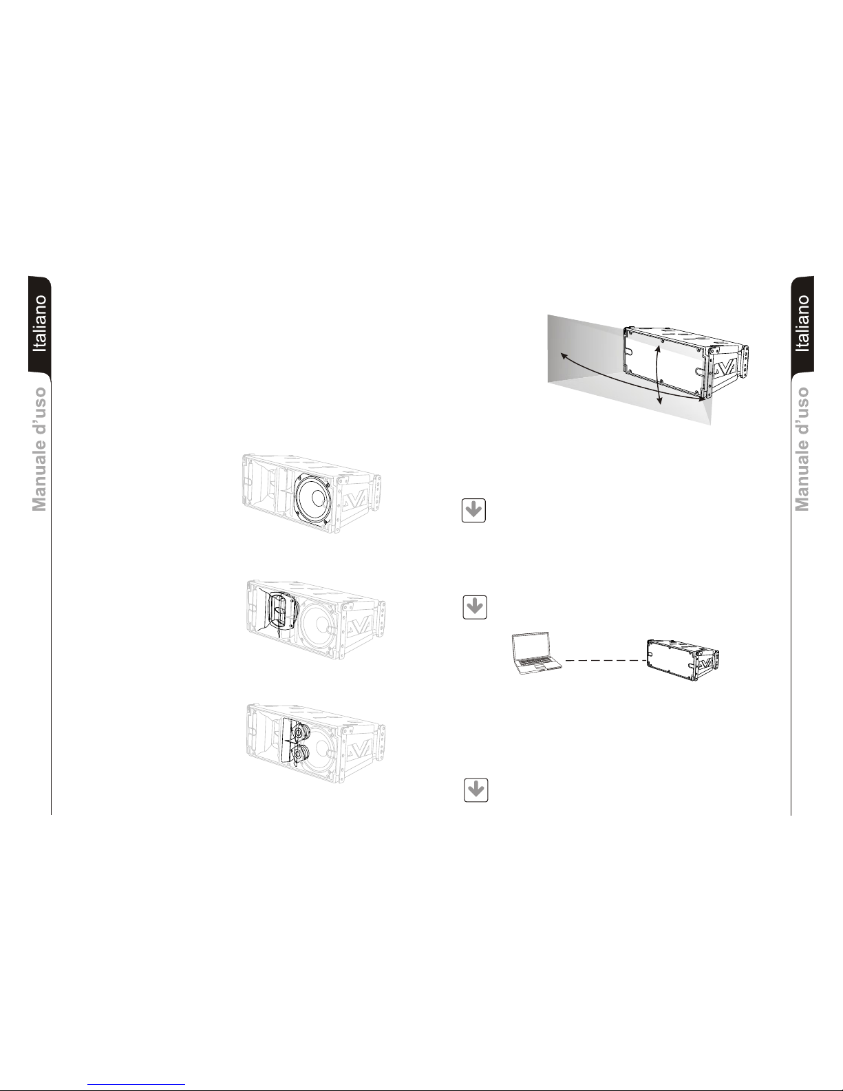
La sezione dei bassi pilota un woofer 8" al
neodimio (voice coil 2,5") garantendo un
elevato SPL ed il raggiungimento di
frequenze basse fino a 70Hz.
La sezione dei medi pilota un midrange,
da 6,5" al neodimio (voice coil 2"),
alloggiati nella propria camera acustica e
caricati a tromba con rifasatore. Il phase
plug montato davanti al cono evita la
sovrapposizioni di fase verticali creando
di fatto un array locale a 3 slot di uscita,
che ne aumenta la direttività.
Il disegno della tromba è stato
appositamente progettato per il corretto
accoppiamento con i moduli DVA T4 e
DVA T12.
La sezione degli alti pilota due
compression driver da 1" al neodimio
(voice coil 1.4") montati verticalmente e
distanziati per ottimizzare la copertura
verticale.
Il disegno della tromba è stato
appositamente progettato per il corretto
accoppiamento con i moduli DVA T4 e
DVA T12
Una progettazione mirata ha permesso di raggiungere una costante e precisa copertura
di 100° in senso orizzontate e 15° in senso verticale per ogni diffusore.
100°
15°
ItalianoItalianoItaliano
Manuale d’usoManuale d’uso
2
ItalianoItalianoItaliano
Manuale d’usoManuale d’uso
1
PC
DVA Network
Il DVA T8 è equipaggiato con interfaccia di rete proprietaria, denominata RDNET tramite
la quale è possibile interfacciarsi al computer attraverso una periferica (RDNET control).
A questo scopo è stato sviluppato il protocollo proprietario di comunicazione RDnet con il
quale è possibile ricevere e inviare i dati; questo collegamento permette di monitorare in
tempo reale i parametri del diffusore come livello del segnale, stato del limiter, etc...
E’ possibile selezionare diversi valori di crossover, delay, volume ed aggiungere
equalizzazioni, tramite l’apposito plug-in.
DVA USB Manager
Si raccomanda di scaricare gratuitamente il software DVA Network
direttamente dal sito dB Technologies (www.dbtechnologies.com) nella
sezione dedicata «Software & Controller»
Il firmware del modulo amplificatore può essere aggiornato attraverso la porta USB.
Per rendere possibile e facile questo aggiornamento è stato sviluppato un software
dedicato.
Si raccomanda di scaricare gratuitamente il software DVA USB Manager
direttamente dal sito dB Technologies (www.dbtechnologies.com) nella
sezione dedicata «Software & Controller»
DVA Composer - Simulazione acustica di sistemi serie DVA
DVA Composer è un software di puntamento e simulazione acustica per tutti i modelli
Line Array della serie DVA e relativi Subwoofers.
Tale software permette di gestire un sistema stereo composto da line array e subs,
simulando separatamente la risposta acustica di entrambi
Vengono inoltre fornite all'utente una serie di informazioni quali allineamento in fase
tra i sistemi sospesi e i relativi subwoofer a terra e vengono suggeriti angoli ottimali tra
i moduli line array e relativi preset di equalizzazione, al fine di ottimizzare le
performance del sistema anche per utenti non esperti.
Si raccomanda di scaricare gratuitamente il software DVA_Composer
direttamente dal sito dB Technologies (www.dbtechnologies.com) nella
sezione dedicata «Software & Controller»
DOWNLOAD
DOWNLOAD
DOWNLOAD
Page 3
7
15
16
17
!!
Made in Italy
Input
Link
Audio
Input Sens
READY
MUTE/PROT
SIGNAL
LIMITER
0dB
+10dB
+4dB
1 = GND
2 = HOT
3 = COLD
1
0
2
3
4
5
6
7
8
9
Active
Data
Link
Link
Active
Data
Input
Input Control
Balanced Audio
Status
Service
Data
User
Remote
Preset
DSP Configuration
SERIAL N.
“CAUTION”
RISK OF ELECTRICAL SHOCK
DO NOT OPEN
“AVIS”
RISQUE DE CHOCH ELECTRIQUE
NE PAS OUVRIR
dd
BB
TECHNOLOGIESTECHNOLOGIES
(REPLACE FUSE WITH SAME RATINGS)
MAINS
FUSE
220-240V~
(18Amax)
3680Wmax
100-120V~
(16Amax)
1320Wmax
100-120V~
4Amax
MAINS
LINK
MAINS
INPUT
FULL RANGE
ACTIVE P.F.C.
100-240V~ 50-60Hz
Digital Vertical Array
8
220-240V~
2Amax
220-240V~
(T3,15A L 250V~)
100-120V~
(T6,3A L 250V~)
PUSH
PUSH
PUSH
1
2
6
5
4
3
11
10
98
14
13
12
ItalianoItalianoItaliano
Manuale d’usoManuale d’uso
3
ItalianoItalianoItaliano
Manuale d’usoManuale d’uso
4
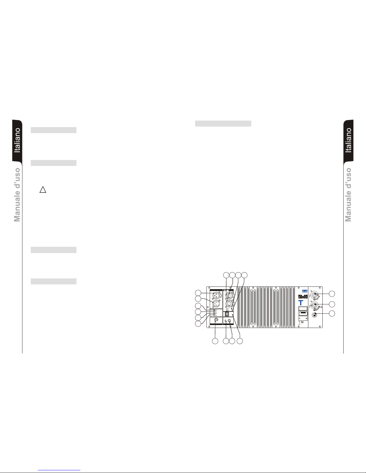
Sezione “DSP configuration”
12) INDICATORE LUMINOSO “Remote Preset Active”
L’accensione di questo indicatore di colore Giallo indica l’esclusione del comando
Volume e del commutatore rotativo “DSP Preset” (13) quando l’amplificatore è
controllato in remoto da un computer tramite RDNET.
L’indicatore lampeggia lentamente se il selettore rotativo è in posizione 9 ed è stata
memorizzata una equalizzazione utente precedentemente salvata.
13) SELETTORE ROTATIVO a 10 posizioni “DSP Preset”
Questo commutatore rotativo a 10 posizioni permette di selezionare le nove curve di
equalizzazione predisposte (selettore da 0-8) o di richiamare l’equalizzazione
precedentemente salvata dall’utente tramite RDNET (selettore 9).
Nel caso in cui non venga utilizzata questa opzione la curva 9 sarà uguale alla curva 0
Consultare la tabella per la corrispondenza delle curva di equalizzazione.
14) Connettore “Service Data USB”
Tramite questo connettore USB è possibile aggiornare il firmware del modulo
amplificatore DVA T8 tramite un computer ed un programma dedicato.
15) PRESA DI ALIMENTAZIONE “MAINS INPUT”
Consente la connessione del cavo di alimentazione.
Il connettore utilizzato per il collegamento alla rete è un POWER CON® (blu)
16) PRESA DI ALIMENTAZIONE RILANCIO “MAINS OUTPUT LINK”
Consente di rilanciare l’alimentazione di rete. L’uscita è connessa in parallelo con
l’ingresso (15) e può essere utilizzata per alimentare un altro diffusore amplificato.
Il connettore utilizzato è un POWER CON® (grigio).
17) PORTA FUSIBILE “MAINS FUSE”
Alloggio per fusibile di rete.
COMANDI E FUNZIONI
Sezione “Balanced Audio”
1) CONNETTORE DI INGRESSO " INPUT”
Connettore XLR ingresso bilanciato a livello linea .
2) CONNETTORE DI USCITA "LINK”
Il connettore “XLR” connesso in parallelo con l’ingresso (1) può essere utilizzato per
inviare il segnale audio in ingresso ad un altro diffusore amplificato.
Sezione “Status”
3) INDICATORE LUMINOSO “LIMITER”
Questo indicatore s’illumina di colore rosso per indicare l'intervento del circuito
limitatore interno, il quale evita la distorsione dell'amplificatore e protegge gli
altoparlanti contro sovraccarichi.
Evitare di utilizzare il sistema per lunghi periodi di tempo con l’indicatore
luminoso acceso fisso o lampeggiante.
4) INDICATORE LUMINOSO “SIGNAL”
Questo indicatore si illumina di colore verde per indicare la presenza di un segnale
in ingresso di un livello superiore ai -20dBu.
5) INDICATORE LUMINOSO “MUTE/PROT”
Questo indicatore di colore giallo indica lo stato dell’amplificatore. Nel normale
funzionamento il led è spento; nel caso in cui lampeggi o sia sempre acceso fare
riferimento alla tabella della diagnostica per la verifica dello stato dell’amplificatore.
6) INDICATORE LUMINOSO “READY”
Questo indicatore s'illumina di colore verde per indicare che la tensione di
alimentazione di rete è corretta. Nel normale funzionamento il led è acceso; nel caso
in cui lampeggi o sia spento fare riferimento alla tabella della diagnostica per la
verifica dello stato dell’amplificatore.
Sezione “Input control”
7) CONTROLLO SENSIBILITA’ INGRESSO “INPUT SENS”
Questo controllo regola la sensibilità del segnale in ingresso all’amplificatore.
Tale controllo non influisce sul livello dell’uscita “LINK” (2)
Sezione “RDNET”
8) CONNETTORE DI INGRESSO "DATA INPUT”
Connettore RJ45 ’ingresso dati .
9) CONNETTORE DI USCITA "DATA LINK”
Connettore RJ45 ’uscita dati per il collegamento seriale in cascata.
10) INDICATORE LUMINOSO “LINK”
Questo indicatore di colore Verde si accende solo quando l’amplificatore ha
riconosciuto ed è connesso con unità principale RDNET tramite computer.
11) INDICATORE LUMINOSO “ACTIVE”
Questo indicatore di colore Giallo lampeggia quanto è attiva una trasmissione dati
tra RDNET e modulo amplificatore.
L177007324
REV SW 2.32
Page 4
CARATTERISTICHE E PROTEZIONI
Griglie frontali
Visto l’utilizzo professionale di questi diffusori, i componenti sono protetti frontalmente da
una lamiera forata con spessore 1,2mm e foam interno.
Raffreddamento
Il controllo termico è gestito dal microprocessore centrale (main) che interagendo con i
microprocessori locali (amplificatori e alimentatore) comunica i dati al DSP per le eventuali
correzioni.
In caso di surriscaldamento eccessivo del modulo amplificatore, il volume viene ridotto
gradualmente a step di 0,1dB fino alla stabilizzazione termica del modulo.
Il volume viene ripristinato automaticamente al raggiungimento delle normali temperatura
di esercizio.
Accensione
La regolare accensione del diffusore è garantita da una procedura di inizializzazione
durante la quale il modulo è alimentato dall’alimentatore ausiliare.
Quando tutte le periferiche dell’amplificatore vengono correttamente rilevate viene attivato
l’alimentatore principale.
La tecnologia IPOS (Intelligent Power-On Sequence) introduce un ritardo casuale e
differenziato per ogni modulo prima della accensione della PSU (Power Supply Unit)
principale.
Questo evita che gli spunti di corrente in accensione dei vari moduli si sommino
sovraccaricando la linea di alimentazione AC.
Al termine della procedura di avvio, sul modulo amplificatore solo il LED verde “READY”
rimane acceso fisso.
Indicazioni di guasto e protezioni
Il microprocessore centrale è in grado di segnalare diversi tipi di guasti tramite diversi
lampeggi dei LED “READY”, “MUTE/PROT” e “LIMIT” come riportato nella tabella della
diagnostica
I tre tipi di guasto possibili sono:
1) ATTENZIONE: viene rilevato una errore o un malfunzionamento autoripristinate non
grave e le prestazioni del diffusore non vengono limitate
2) LIMITAZIONE: viene rilevato un errore e vengono limitate le prestazioni del diffusore .
Il livello sonoro viene ridotto oppure vengono disabilitati uno o più amplificatori.
Questo stato influisce parzialmente sul funzionamento corretto del diffusore.
Se il problema persiste alle successive accensioni del modulo è nessario contattare
il centro assistenza per risolvere il problema.
3) GUASTO: viene rilevato un malfunzionamento grave. Il diffusore viene posto nello
stato di “mute”.
Nel caso di malfunzionamento, prima di contattare il centro di assistenza, provare a
spegnere e riaccendere il modulo per verificare la continuità del problema.
Collegamento alla alimentazione di rete
Il collegamento alla rete avviene tramite un connettore modello Neutrik POWER CON®
(blu) che permette di avere una facile e rapida connessione al diffusore oltre che a un
ottimo sistema di bloccaggio.
Lo stesso connettore serve da interruttore per accendere e spegnare il diffusore.
L’apparecchio dovrà essere collegato ad una rete di alimentazione che possa erogare la
massima potenza richiesta.
Rilancio alimentazione di rete
Sul retro del diffusore è presente un connettore Neutrik POWER CON® (grigio) per il
rilancio di alimentazione di rete.
Questa presa ha lo scopo di rilanciare l’alimentazione ad un altro diffusore riducendo i
collegamenti diretti alla rete. Gli assorbimenti massimi degli amplificatori sono riportati sul
pannello dell’amplificatore.
Il numero massimo dei diffusori collegati insieme varia sia per gli assorbimenti massimi
dei diffusori e sia dalla corrente massima della prima presa di alimentazione.
ItalianoItalianoItaliano
Manuale d’usoManuale d’uso
5
ItalianoItalianoItaliano
Manuale d’usoManuale d’uso
6
TABELLA DELLA DIAGNOSTICA
STATO LED LED LED LED FUNZIONI MODULO
DEL MODULO «READY» «MUTE/PROT» «SIGNAL» «LIMIT»
Accensione Spento Acceso per 5 sec. Spento Spento Audio in MUTE
Inizializzazione del modulo amplificatore
Uso normale Acceso fisso Spento Funzionamento normale Funzionamento normale Audio ATTIVO
Inizializzazione del modulo completata e corretta
Anomalia parziale Acceso fisso Lampeggio ciclico Funzionamento normale Funzionamento normale Audio ATTIVO
(3 o più lampeggi veloci) Il modulo ha rilevato una anomalia parziale e rimane
attivo con funzionalità limitate
Anomalia totale Spento Acceso fisso Spento Lampeggio ciclico Audio in MUTE
Il modulo ha rilevato una anomalia grave e rimane in
protezione
Gestione temperatura amplificatore:
Prima soglia Acceso fisso Lampeggio ciclico Funzionamento normale Funzionamento normale Audio ATTIVO
termica (1 lampeggio lento) Il modulo amplificatore comincia una graduale
diminuzione del volume a step di 0.1dBm per
compensare l’ aumento della temperatura fino ad un
massimo di riduzione di 3dBm.
Seconda soglia Acceso fisso Lampeggio ciclico Funzionamento normale Funzionamento normale Audio ATTIVO
termica (2 lampeggi veloci) Il modulo amplificatore riduce il volume di ulteriori 3dBm
sempre a step graduali di 0.1dBm fino ad un massimo
di riduzione di altri 3dBm, per una totale riduzione di
6dBm rispetto al volume originale.
N.B. Le temperature visualizzate sul plug-in del software RDnet si riferiscono alle temperature interne dei semiconduttori di potenza.
Tali temperature visualizzate non sono le temperature delle parti accessibili dall’utente
STATO LED LED LED FUNZIONI MODULO
DEL MODULO « » « » «ACTIVE»
RDNET non attiva Spento Spento Spento Il modulo funziona normalmente
Il volume (INPUT SENS) e il commutatore rotativo (DSP Preset)
sono attivi
RDNET collegata Acceso fisso Acceso fisso Lampeggio ciclico Il modulo amplificatore è controllato in remoto dall’RDNET
(Attività dati) Il volume (INPUT SENS) e il commutatore rotativo (DSP Preset)
sono bypassati
Equlizzazione «USER EQ» Lampeggio ciclico Spento Spento Il modulo funziona normalmente
(commutatore rotativo Si sta utilizzando l’equalizzazione salvata tramite RDNET
«DSP Preset» in posizione 9)
Remote Preset Active LINK
Page 5
CLASSIFICAZIONE EMI
In accordo alle normative EN 55103, l'apparato è progettato e idoneo all'utilizzo in ambienti
Elettromagnetici E3 o inferiori (E2, E1).
DATI TECNICI
Sistema Attivo 3-Amps
Tipologia amplificatore Digitale - Classe D
Tecnologia DIGIPRO G2
Potenza RMS 700W
Alti (HF) RMS 175W
Medi (MF) RMS 175W
Bassi (LF) RMS 300W
Potenza musicale 1400W
Risposta in frequenza (-6dB) 66-18.000Hz
Risposta in frequenza (-10dB) 61-19.900Hz
Crossover MF-HF (Medi-Alti) 1900Hz
24dB/Oct
Crossover LF-MF (Bassi -Medi) 400Hz
24dB/Oct
Pressione sonora (SPL) 132dB max
Componenti 1 Woofer 8" - VC 2,5" - Neodimio
1 Midrange 6,5" - VC 2" - Neodimio
2 Compression Driver 1" - VC 1.4" - Neodimio
Sensibilità ingresso nominale 0dBu
Impedenza ingresso
Bilanciato 20Kohm
Sbilanciato 10Kohm
Alimentazione Full-range con PFC e SMPS
100-240V~ 50-60Hz
Corrente di accensione 3,3A
Dimensioni (LxHxP) 580x386x327mm
(23,2x9,6x13,08 inch.)
Peso 14,2Kg
(31,3 lbs)
PROCESSORE DSP
®
DSP Analog Device 56 bits
Conversione audio 24 bit / 96kHz S/N=114dB
Controllo volume Digitale
Equalizzazione 9 preset EQU
MECCANICA
Materiale box Polipropilene (PP)
Rinforzi interni box Acciaio
Materiale staffe appendibilità Acciaio
Angolazioni staffe 0° - 1,5° - 3° - 4,5° - 6° - 8° - 10° - 12,5° - 15°
Forma del diffusore Trapeziodale - angolazione 15°
Maniglia 1 x lato
Rete frontale Lamiera forata 1.2mm con foam interno.
ItalianoItalianoItaliano
Manuale d’usoManuale d’uso
7
DRK 10
Il sistema DVA ha ottenuto la certificazione TÜV per la sospensione dei diffusori DVA T4,
DVA T8, DVA T12, DVA S09dp, DVA S10dp, DVA S1518N e DVA S2585N tramite la staffa
flybar DRK 10 per un peso massimo applicabile al flybar DRK10 è di 250kg.
PERICOLO! Rispettare attentamente il carico ammesso il funzione del punto di
fissaggio del gancio di sollevamento.
Il non rispetto di tutte le avvertenze può provocare pericolo di caduta della struttura e del
suo contenuto con potenziali danni a persone, animali e cose.
Configurazioni con DVAT8
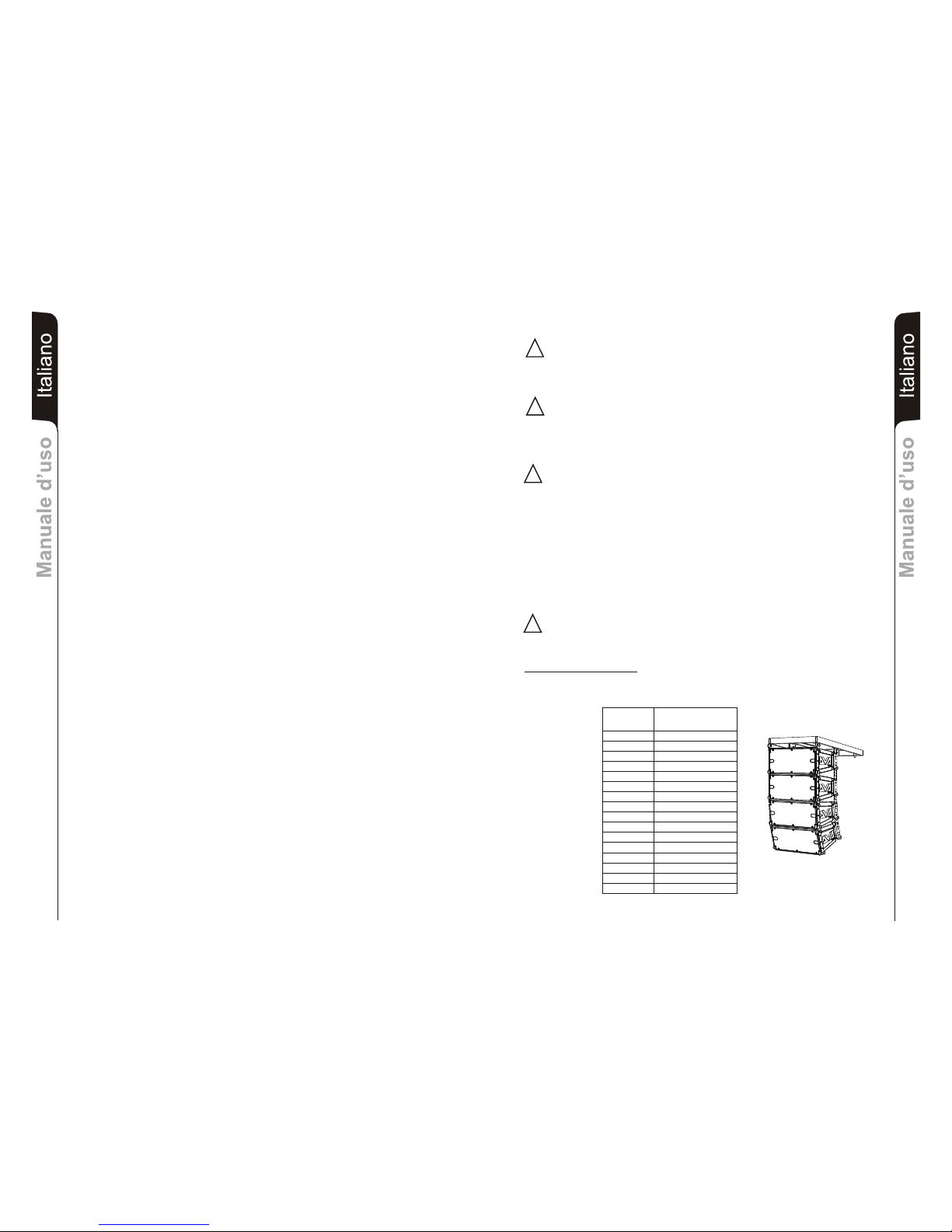
Il flybar DRK10 è certificato per un carico massimo di 16 diffusori DVA T8
Fare riferimento alla tabella 1 per determinare il peso complessivo sopportato dal flybar
con diffusori DVA T8
Quantità Peso
[kg] [lbs.]
1 15 33
2 30 66
3 45 99
4 60 132
5 75 165
6 90 198
7 105 231
8 120 264
9 135 297
10 150 330
11 165 363
12 180 396
13 195 429
14 210 462
15 225 495
Tabella 1 16 240 528
INSTALLAZIONE
!
!
!
!
ATTENZIONE
Installare il diffusore in modo stabile e sicuro, così da evitare qualsiasi condizione di
pericolo per l’incolumità di persone e strutture.
Prima si sospendere il diffusore controllare tutti i componenti da utilizzare, che non
devono presentare danni, deformazioni, parti mancanti o danneggiate che possono
ridurre la sicurezza dell’installazione.
ATTENZIONE
L'utilizzo del diffusore su supporto piantana deve essere effettuato
esclusivamente da personale professionale qualificato, prestando attenzione a
posizionare un piede del supporto piantana in direzione del lato di uscita del suono
(lato anteriore del diffusore) in modo da massimizzare la stabilità in relazione al
baricentro del diffusore (rif. pag.58).
ATTENZIONE
Nell'utilizzo del diffusore con supporto per subwoofer -pole mount- (rif. Pag.59), al
fine di evitare pericoli di ribaltamento e di danni a persone, animali e cose, prima di
procedere all'installazione del sistema, verificare sul sito dBTechnologies le
configurazioni ammesse, le indicazioni e relative prescrizioni. In ogni modo
assicurarsi che il subwoofer di supporto del diffusore sia posizionato su una
superficie orizzontale priva di inclinazioni.
ItalianoItalianoItaliano
Manuale d’usoManuale d’uso
8
Page 6
Configurazioni con DVAS1518N
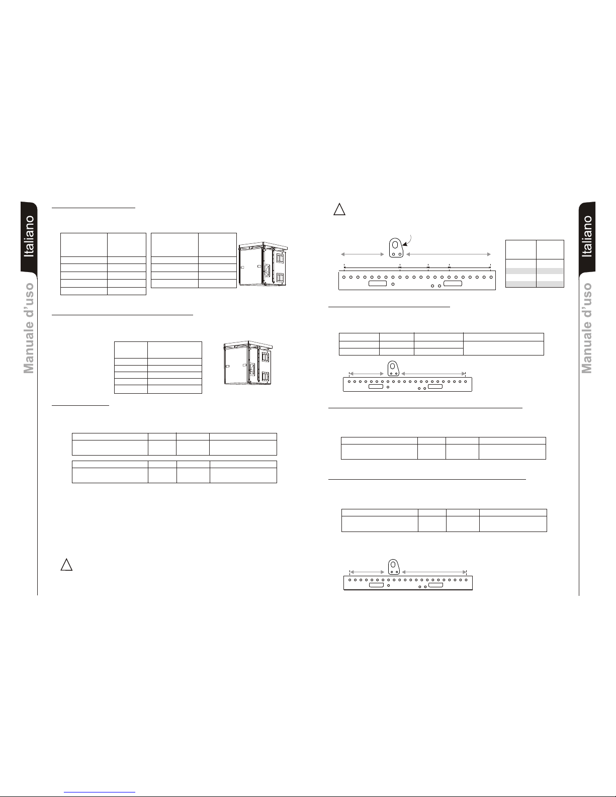
Il flybar DRK10 è certificato per un massimo di 5 diffusori DVA S1518N
Fare riferimento alla tabella 3 per determinare il peso complessivo sopportato dal flybar
con diffusori DVA S1518N
Quantità Peso
[Kg] [lbs.]
1 46 102
2 92 203
3 138 304
Tabella 3 4 184 405
5 203 507
(Woofer Neodimio)
Configurazioni con DVA S10dp
Il flybar DRK10 è certificato per un massimo di 5 diffusori DVA S10dp (woofer Neodimio) e
4 diffusori DVA S10dp (woofer Ceramico)
Fare riferimento alla tabella 2 per determinare il peso complessivo sopportato dal flybar.
Quantità Peso x qtà Peso configurazione
DVA T8 8 120Kg
DVA S10dp(woofer Neodimio) 2 96Kg
Quantità Peso x qtà Peso configurazione
DVA T8 12 180Kg
DVA S1518N (woofer Neodimio) 1 46Kg
216Kg
226Kg
Configurazioni miste
La modularità del sistema DVA permette configurazioni sospese miste tra diffusori.
Per questo motivo è necessario calcolare il carico totale nelle diverse combinazioni.
Esempio:
Quantità Peso
DVA S10dp [kg] [lbs]
(Woofer Neodimio)
1 48 106
2 96 212
3 144 317
4 192 423
5 240 528
Quantità Peso
DVA S10dp [kg] [lbs]
(Woofer Ceramico)
1 54 119
2 108 238
3 162 357
4 216 476
DRK 20
Il dispositivo Fly Bar DRK 20 e i relativi sistemi di appendibilità previsti per i diffusori
DVA T4, DVA T8, DVA T12, DVA S09dp, DVA S10dp, DVA S1518N e DVA S2585N sono
stati progettati e verificati mediante prove tecniche di rottura in accordo ai documenti,
Decreto Ministeriale Italiano D.M. del 14.01.2008 “Nuove norme tecniche per le
costruzioni” ed “Eurocodice 1” e Eurocodice 3” per quanto concerne le strutture in acciaio.
Il sistema è stato verificato tecnicamente e attestato conforme ai valori di massima portata
dichiarati mediante Attestato di Conformità emesso da CERMET, n.reg. PA 68913 V
00001 2011.
Il DRK 20 deve essere utilizzato solo da personale qualificato!
I calcoli strutturali attestano che il peso massimo applicabile al flybar DRK20 è in funzione
del punto di attacco del gancio di sollevamento. Per i dettagli fare riferimento al manuale
dedicato.
!
Tabella 2
5
4
6
2
1
3
11
10
12
8
7
9
17
16
18
14
13
15
22
20
19
21
1200Kg
(12KN)
1000Kg
(10KN)
1300Kg
(13KN)
750Kg
(7.5KN)
Posizione Carico
gancio di massimo
sollevamento appendibile
1 - 9 1200kg
9 - 13 1300kg
13 - 16 1000kg
16 - 22 750kg
GANCIO DI SOLLEVAMENTO
Configurazioni miste con DVA T8 e DVA T12
La modularità del sistema DVA permette configurazioni sospese miste tra diffusori
DVA T8 e DVA T12. Per questo motivo è necessario calcolare il carico totale.
Esempio:
Quantità Peso x qtà Peso configurazione
DVA T12 10 300Kg
DVA T8 6 90Kg
390Kg
5
4
6
2
1
3
11
10
12
8
7
9
17
16
18
14
13
15
222019
21
Configurazioni con miste con DVA T8 e DVA S1518N (Woofer neodimio)
La modularità del sistema DVA permette configurazioni sospese miste tra diffusori DVA
T8 e DVA S1518N. Per questo motivo è necessario calcolare il carico totale.
Esempio:
5
4
6
2
1
3
11
10
12
8
7
9
17
16
18
14
13
15
222019
21
Configurazioni con miste con DVA T8 e DVA S10dp (Woofer neodimio)
La modularità del sistema DVA permette configurazioni sospese miste tra diffusori
DVA T8 e DVA S10dp. Per questo motivo è necessario calcolare il carico totale.
Esempio:
PERICOLO! Rispettare attentamente il carico ammesso il funzione del punto di fissaggio
del gancio di sollevamento.
Il non rispetto di tutte le avvertenze può provocare pericolo di caduta della struttura e del
suo contenuto con potenziale danni a persone, cose e animali.
!
Quantità Peso x qtà Peso configurazione
DVA T8 14 210Kg
DVA S10dp(woofer Neodimio) 4 192Kg
Quantità Peso x qtà Peso configurazione
DVA T8 20 300Kg
DVA S1518N (woofer Neodimio) 4 184Kg
402Kg
484Kg
ItalianoItalianoItaliano
Manuale d’usoManuale d’uso
9
ItalianoItalianoItaliano
Manuale d’usoManuale d’uso
10
Page 7
DESCRIPTION
The DVA T8 is equipped with three class D amplifiers of DIGIPRO® G2 series, high
efficiency, which delivers high output power in a compact size and low weight. Thanks to
its high efficiency the cooling of the amplifier module is obtained statically, thus avoiding
the use of a fan.
®
The power supply circuits of the DIGIPRO G2 amplifier has been conceived to work in
full-range mode; thanks to the SMPS (Switched-Mode Power Supplies) technology with
PFC (Power Factor Correction) the operation with supply voltages between 100 Vac and
240Vac is guaranteed by ensuring the same sound performances even with floating and
non-stabilized power supply systems.
The amplifier module is able to deliver 350W (RMS) for the bass section, 175W (RMS) for
the mid-section and 175W (RMS) for the treble section.
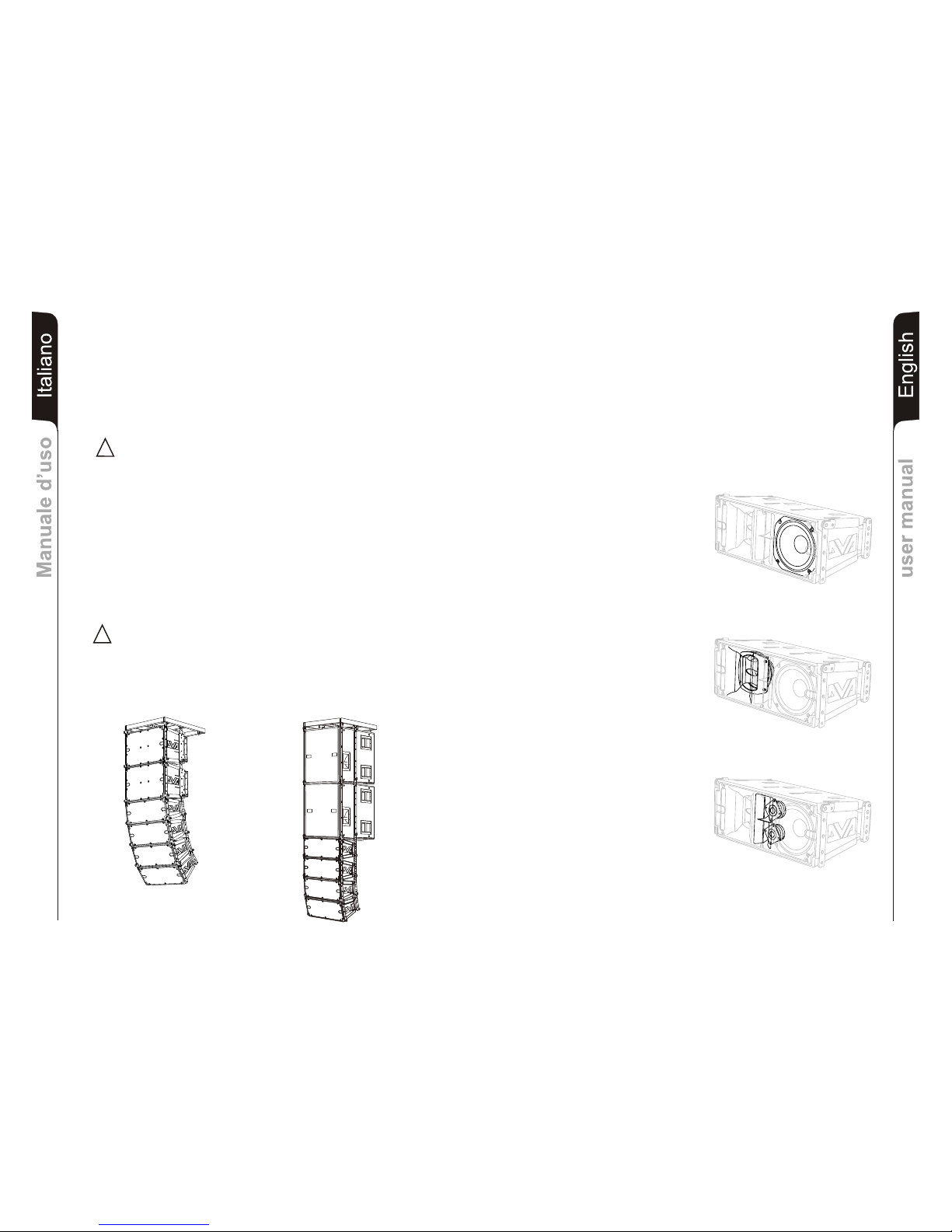
The bass section controls a 8"
neodymium woofer (2.5" voice coil)
guarantees a high SPL and the
obtainment of frequencies of up to 70Hz.
The mid-section controls one 6.5"
neodymium midranges (2" voice coil),
enclosed in its own acoustic chamber
and horn loaded with a power factor
corrector. The plug phases located in
front of the cones prevent the vertical
phases from overlapping, creating in fact
a local array with 3 output slot that
increases directivity. The horn design
was specifically created to couple it
correctly with the DVA T4 and DVA T12
modules.
The treble section controls two 1"
neodymium drivers (1.4" voice coil)
positioned vertically and spaced to
optimize the vertical cover. The horn
design was specifically created to couple
it correctly with the DVA T4 and DVA T12
modules.
EnglishEnglishEnglish
user manualuser manual
12
Modifiche strutturali alla supporto flybar
Accessori originali dBTechnologies
Inizio e funzionamento
E’ vietato apportare qualunque modifica alla struttura del flybar e relative staffe a corredo
dei diffusori stessi.
Manomettere e/o modificare la struttura o gli accessori a corredo può provocare pericolo
di cedimenti o rottura.
E’ vietato utilizzare parti e accessori diversi da quelli forniti a corredo.
Utilizzare solo parti originali fornite da dBTechnologies.
Ogni installazione ed utilizzo delle parti fornite deve essere eseguito in accordo alle
istruzioni di montaggio a corredo.
Conservare ed archiviare tutti i documenti del sistema DVA in un posto sicuro!
Attenzione
La dB Technologies non può essere ritenuta responsabile di danne a persone, a
cose ed animali nel caso in cui le prescrizioni di sicurezza e i calcoli dei pesi massimi
non siano rispettati!
Note
Durante le installazioni accertarsi che nella struttura portante del sistema vengano inclusi
nel calcolo dei pesi totali anche il peso del flybar, delle catene dei sollevatori, dei motori,
dei cavi e ulteriori pesi aggiuntivi.
§ 39, VBG 9a sull'assicurazione obbligatoria da parte datori di lavoro Tedeschi per la
prevenzione degli incidenti richiede che l'equipaggiamento del carico-portante debba
essere ispezionato da personale qualificato ed i possibili difetti debbano essere eliminati
prima della consegna al utente finale.
§ 41 VBG 9a richiede che l'equipaggiamento del carico-portante debba essere soggetto a
una manutenzione non ordinaria successivamente a danni, riparazioni e altri incidenti che
possono avere effetto sulla capacità del carico-portante.
Attenzione
Le normative sulla sicurezza possono essere diverse in funzione del paese di
destinazione. L’utilizzatore è tenuto a verificare le regolamentazioni e le leggi
cogenti in materia di sicurezza nel paese in cui utilizza il prodotto!
DVA T8
DVA T12
DVA T8
DVA S1518N
!
!
ItalianoItalianoItaliano
Manuale d’usoManuale d’uso
11
Page 8
EnglishEnglishEnglish
user manualuser manual
14
user manualuser manual
EnglishEnglishEnglish
13
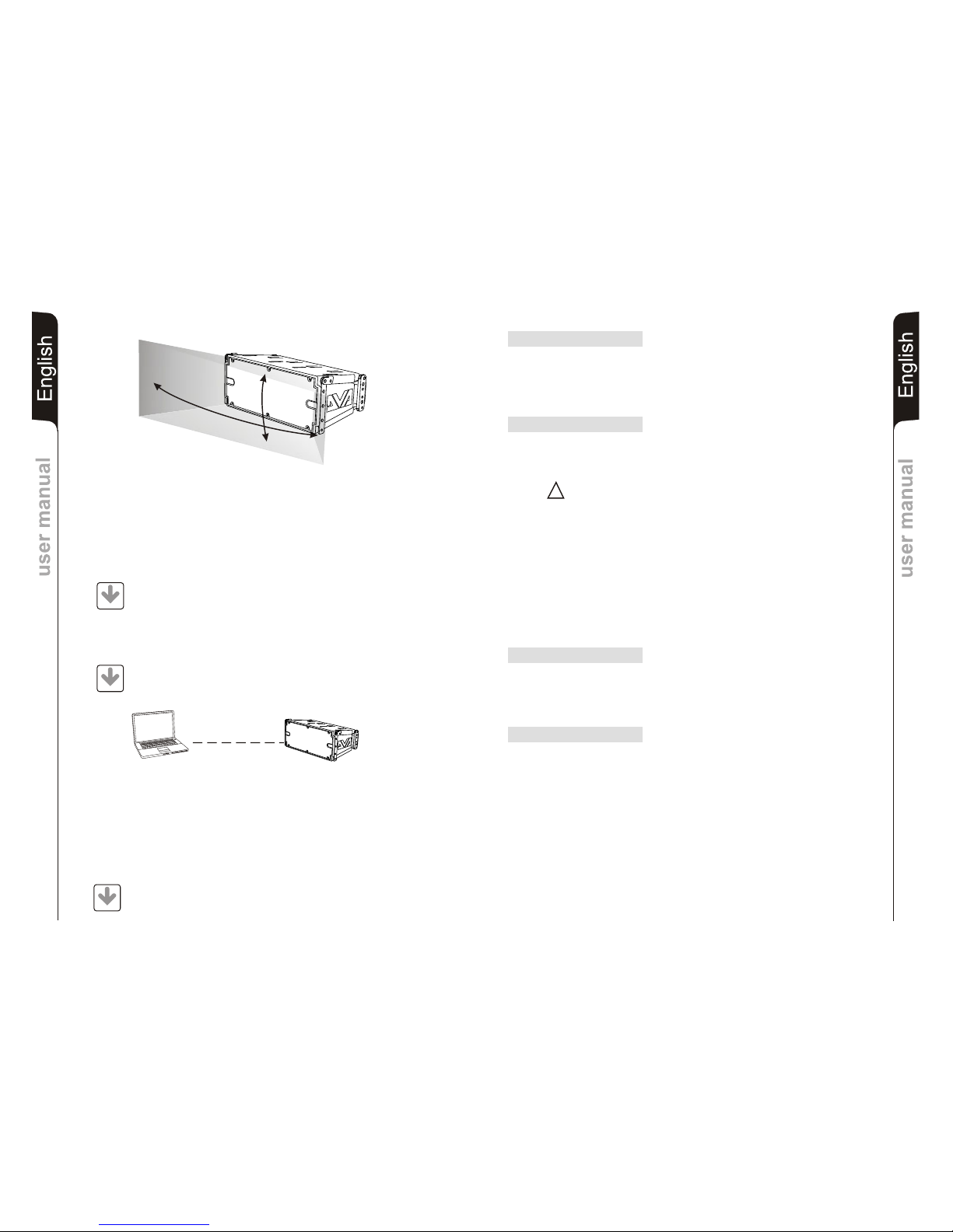
This specific design has made it possible to obtain a constant and precise 100° coverage
in a horizontal direction and 15° coverage in a vertical director for each diffuser.
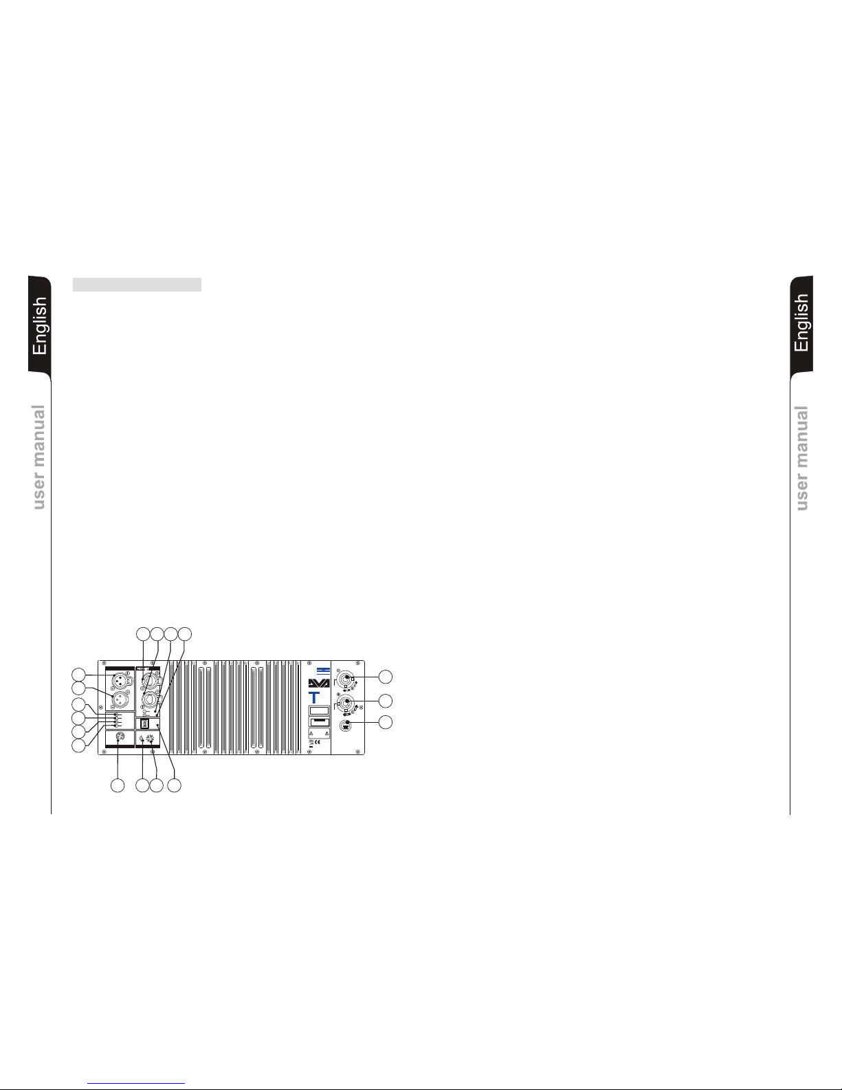
CONTROLS AND FUNCTIONS
"Balanced Audio" section
1) " INPUT” INPUT CONNECTOR
Balanced input at line level. It is able to accept “XLR” sockets.
2) "LINK” OUTPUT CONNECTOR
The “XLR” connector connected in parallel with input (1) can be used to send the
input audio signal to another amplified speaker.
"Status" section
3) “LIMITER” INDICATOR LIGHT
This indicator comes on red to indicate that the internal limiter circuit has tripped.
This prevents amplifier distortion and protects the speakers against overloads.
Always avoid operating conditions where the system works for long periods of
time with LED flashes or it is always ON
4) “SIGNAL” INDICATOR LIGHT
This indicator comes on green to indicate the presence of an input signal to a level
higher than-20dBu.
5) “MUTE/PROT” INDICATOR LIGHT
This yellow indicator indicates amplifier status. In normal operating conditions, the
LED is off; if it flashes or is always on, refer to the diagnostics table to check amplifier
status.
6) “READY” INDICATOR LIGHT
This indicator comes on green to indicate that the main power voltage is correct. In
normal operating conditions, the LED is on; if it flashes or is off, refer to the
diagnostics table to check amplifier status.
"Input control " section
7) “INPUT SENS” INPUT SENSITIVITY CONTROL
This control regulates the sensitivity of the signal amplifier input.
This control does not affect the “BALANCED LINK/OUT” output level
"RDNET " section
8) INPUT CONNECTOR "DATA INPUT”
RJ45 connector 'data input.
9) OUTPUT CONNECTOR "DATA INPUT”
RJ45 connector 'data output for cascading connections.
10) “LINK” INDICATION LIGHT
This green indicator turns on only when the amplifier has recognized and is
connected with the main RDNET unit via the computer.
11) “ACTIVE” INDICATOR LIGHT
This yellow indicator flashes when there is an active data transmission between
RDNET and the amplifier module.
!!
100°
15°
DVA Network
DVA USB Manager
The firmware of the amplifier module can be updated via the USB port.
To make this update possible and simple, a dedicated program has been developed.
DVA T8 is equipped with proprietary network interface, called RDNET, for PC interface
through a device (RDNET control).
For this purpose, a proprietary communication protocol has been developed for receiving
and sending data; this connection permits real-time monitoring of the diffuser parameters,
such as output power, amplifier temperature, limiter status, etc...
It is also possible to select various equalizations or create new ones, set the desired
volume levels using the specific plug-in.
It is recommended to download DVA Network free software directly from
dB Technologies (www.dbtechnologies.com) in the special section
«Software & Controller»
It is recommended to download DVA USB Manager free software directly
from dB Technologies (www.dbtechnologies.com) in the special section
«Software & Controller»
DVA Composer Acoustical Simulation and aiming for DVA Systems
DVA Composer is a 2D software for aiming and simulating acoustical response of all line
arrays and Subwoofers from DVA Series.
The software allows you to set up a stereo system composed by tops and subs, and
simulates separately the acoustical response of both
DVA Composer also gives to the user all the information about phase alignment between
flown systems and ground stacked subwoofers, as well as it suggests an optimized
aiming of the line arrays modules and their suggested EQ presets, in order to guarantee
maximum performances even for non-expert customers.
It is recommended to download DVA_Composer free software directly from
dB Technologies (www.dbtechnologies.com) in the special section «Software
& Controller»
PC
DOWNLOAD
DOWNLOAD
DOWNLOAD
Page 9
EnglishEnglishEnglish
user manualuser manual
16
user manualuser manual
EnglishEnglishEnglish
15
"DSP configuration" section
12) “Remote Preset Active” INDICATION LIGHT
This yellow indicator indicates the exclusion of the Volume control and the “DSP
Preset” rotary switch (13) when the amplifier is remotely controlled by a
computer via RDNET.
The indicator flashes slowly if the rotary switch is set to 9 and a previously saved
user equalization has been stored.
13) “DSP Preset” 10-position ROTARY SWITCH
This 10-position rotary switch makes it possible to select the nine preset
equalization curves (selector 0-8) or to select the equalization previously saved
by the user via RDNET (selector 9).
If this option is not used, curve 9 will be equal to curve 0
Refer to the table for the correspondence of the equalization curve.
14) “Service Data USB” Connector
Via this USB connector, it is possible to update the firmware of the DVA T8
amplifier module using the computer and a dedicated program.
15) "MAINS INPUT" POWER SOCKET
For connecting the power cable.
The connector used for mains connection is a POWER CON® (blue)
16) “MAINS OUTPUT LINK” RELAUNCH POWER SOCKET
For relaunching the mains power. The output is connected in parallel with input (15)
and can be used to power another amplified speaker.
The connector uses a POWER CON® (grey)
17) "MAINS FUSE" FUSE CARRIER
Mains fuse housing.
CHARACTERISTICS AND PROTECTION
The speakers’s components in the box are protected by 1.2mm metal steel grille
covered by foam on backside.
Cooling
Thermal control is managed by the main microprocessor that interacts with the local
microprocessors (amplifiers and power supply) and communicates the data to the
DSP for any corrections.
If the amplifier module heats up excessively, the volume is gradually reduced step
wise to 0.1dB until the module is thermally stabilised.
The volume is automatically restored when the normal operating temperature is
reached.
Power on
The diffusor is powered up normally by an initialization process during which the
module is powered by the auxiliary power supply.
When all of the amplifier peripherals are correctly detected, the main power supply is
activated.
The IPOS technology (Intelligent Power-On Sequence) introduces a random and
differentiated delay for each module prior to the power on of the main PSU (Power
Supply Unit).
This prevents the breakaway starting currents of the various modules from
accumulating, overloading the AC power supply line.
At the end of the power on procedure, only the green “READY” LED will remain on
fixed on the amplifier module.
Failure indications and safeties
The microprocessor is able to signal three different kinds of failure by flashing the
“READY”, “ ” and “LIMIT” LED as reported in the table of diagnostic.
The three types of failure are:
1) WARNING: a non severe error or auto-ripristinate malfunction is detected and the
performance of the speaker is not limited
2) LIMITATION: an error is detected and diffuser performance is limited. The sound
level is reduced or one or more amplifiers are disabled.
This state partially influences the correct functioning of the diffuser.
If the problem persists the next time the module is turned on, contact the support
centre for assistance.
3) FAILURE: a severe malfunction is detected. The speaker switches to “mute”.
If the case of a malfunction, before contacting the support centre, try to turn the
module off and on to check if the problem still exists.
Connecting to the mains supply
Each active speaker features its own power cable. Connection is done by a Neutrik
POWER CON® (blue) model which permits easy and fast connection to the speaker
as well as being an excellent locking system.
The same connector serves as a switch to turn ON and OFF the active loudspeaker by
turning the connector to the left (OFF) or right (ON).
The active speaker must be connected to a power supply able to deliver the maximum
required power.
Main power supply linking
On the rear of the speaker, a Neutrik POWER CON® connector (grey) offers linking
the mains power supply.
This socket links the power supply to another speaker, thereby reducing the direct
connections to the mains. Maximum amplifier input power is shown on the amplifier
panel.
The maximum number of speakers connected together varies of max input power
and of the maximum allowed current of the first power socket.
Front Grille
MUTE/PROT
7
15
16
17
Made in Italy
Input
Link
Audio
Input Sens
READY
MUTE/PROT
SIGNAL
LIMITER
0dB
+10dB
+4dB
1 = GND
2 = HOT
3 = COLD
1
0
2
3
4
5
6
7
8
9
Active
Data
Link
Link
Active
Data
Input
Input Control
Balanced Audio
Status
Service
Data
User
Remote
Preset
DSP Configuration
SERIAL N.
“CAUTION”
RISK OF ELECTRICAL SHOCK
DO NOT OPEN
“AVIS”
RISQUE DE CHOCH ELECTRIQUE
NE PAS OUVRIR
dd
BB
TECHNOLOGIESTECHNOLOGIES
(REPLACE FUSE WITH SAME RATINGS)
MAINS
FUSE
220-240V~
(18Amax)
3680Wmax
100-120V~
(16Amax)
1320Wmax
100-120V~
4Amax
MAINS
LINK
MAINS
INPUT
FULL RANGE
ACTIVE P.F.C.
100-240V~ 50-60Hz
Digital Vertical Array
8
220-240V~
2Amax
220-240V~
(T3,15A L 250V~)
100-120V~
(T6,3A L 250V~)
PUSH
PUSH
PUSH
1
2
6
5
4
3
11
10
98
14
13
12
L177007324
REV SW 2.32
Page 10
EnglishEnglishEnglish
user manualuser manual
18
user manualuser manual
EnglishEnglishEnglish
17
TECHNICAL SPECIFICATION
System Active 3-Amps
Type of amplifier Digital - Class D
DIGIPRO G2 technology
RMS power 700W
High (HF) RMS 175W
Mide (MF) RMS 175W
Low (LF) RMS 300W
Musical power 1400W
Frequency response (-6dB) 66-18.000Hz
Frequency response (-10dB) 61-19.900Hz
Crossover MF-HF (Mid-High) 1900Hz
24dB/Oct
Crossover LF-MF (Low-Mid) 400Hz
24dB/Oct
Sound pressure (SPL) 132dB max
Component parts 1 woofer 8" - VC 2.5" - Neodymium
1 midrange 6,5" - VC 2" - Neodymium
2 compression driver 1" - VC 1.4" -
Neodymium
Input sensitivity nominal 0dBu
Input impendence
Balanced 20Kohm
Unbalanced 10Kohm
Power supply Full-range with PFC and SMPS
100-240V~ 50-60Hz
Inrush current 3,3A
Dimension (WxHxD) 580x386x327mm
(23,2x9,6x13,08 inch.)
Weight 14,2Kg
(31,3 lbs)
DSP PROCESSOR
DSP Analog Device 56 bits
Audio conversion 24 bit / 96kHz S/N=114dB
Volume control Digital
Equalization 9 preset EQU
MECHANICAL PARTS
Box material Polipropilene (PP)
Box internal reinforcement Steel
Flying support material Steel
Stirrup angle 0° - 1,5° - 3° - 4,5° - 6° - 8° - 10° - 12,5° - 15°
Housing shape Trapezoidal - angle 15°
Handle 1 x side
Rear grille Performed sheet 1.2mm with internal foam
®
EMI CLASSIFICATION
According to the standards EN 55103 this equipment is designed and suitable to operate in E3
(or lower E2, E1) Electromagnetic environments.
MODULE LED LED LED LED
STATUS «READY» «MUTE/PROT» «SIGNAL» «LIMIT»
Power ON OFF ON for 5 sec. OFF OFF
Normal use ON OFF
Partial fault ON
Total fault OFF ON OFF
Amplifier temperature management:
First thermal ON
threshold The amplifier module begins a gradual
decrease of the volume in 0.1dBm steps to
compensate 'temperature increase up to a
maximum reduction of 3dBm.
Second thermal ON Audio ACTIVE
threshold The amplifier module reduces the volume further 3dBm
always in 0.1dBm steps up to a maximum reduction of
6dBm respect original volume.
NB The temperatures shown on the plug-in RDnet software refer to the internal temperature of the power semiconductors.
These temperatures are not displayed the temperatures of accessible parts user
MODULE FUNCTIONS
Audio MUTED
Initialization of the amplifier module
Normal operation Normal operation Audio ACTIVE
Module initialization complete and correct
Cyclic flashing Normal operation Normal operation Audio ACTIVE
(3 or more quick flashes) The module has detected a partial anomaly
and remains active with limited functions
Cyclic flashing Audio MUTED
The module has detected a serious anomaly
and is in protected mode
Cyclic flashing Normal operation Normal operation Audio ACTIVE
(1 slow flashes)
Cyclic flashing Normal operation Normal operation
(2 quick flashes)
DIAGNOSTICS TABLE
MODULE STATUS LED LED LED MODULE FUNCTIONS
« » « » «ACTIVE»
RDNET not active OFF OFF OFF
RDNET connect ON ON
OFF OFF
Remote Preset Active LINK
The module is functioning normally.
The volume (INPUT SENS) and the rotary switch (DSP Preset)
are active
Cyclic flashing The amplifier module is remotely controlled by RDNET.
The volume (INPUT SENS) and the rotary switch (DSP Preset)
are bypassed
Equalization «USER Eq» Cyclic flashing The module functions normally.
(rotary switch The equalization saved by means of RDNET is being used.
«DSP Preset» set to 9)
Page 11
19
EnglishEnglishEnglish
user manualuser manual
DRK 10
DVA system has obtained the TÜV certification for suspension of DVA T4, DVA T8,
DVA T12, DVA S09dp, DVA S10dp, DVA S1518N and DVA S2585N speakers through
flybar stirrup DRK 10 for maximum weight applying is 250Kg.
WARNING! Observe with particular attention the maximum load allowed.
Failure to comply with all warnings may cause danger of structure and content falling
with potential damage to people, things and animals.
Quantity Weight
DVA S10dp [kg] [lbs]
(Neodymium woofer)
1 48 106
2 96 212
3 144 317
4 192 423
5 240 528
Quantità Weight
DVA S10dp [kg] [lbs]
(Ceramic woofer)
1 54 119
2 108 238
3 162 357
4 216 476
INSTALLATION
DVA S1518N configuration
(Neodymium woofer)
(Neodimium woofer)
The DRK 10 flybar attests that the maximum number of DVA S1518N is 5.
Refer to table 3 to determine the total weight borne by flybar according to the different
configurations.
Quantity Weight
[kg] [lbs.]
1 46 102
2 92 203
3 138 304
Table 3 4 184 405
5 230 506
Mixed configuration
The modular structure of DVA system permits mixed suspension configuration between
speakers.
For this reason it is necessary to calculate the total weight according to the different
configurations.
Examples:
DRK 20
The DRK 20 flybar system and its rigging systems used for DVA T4, DVA T8, DVA T12,
DVA S09dp, DVA S10dp, DVA S1518N e DVA S2585N speakers is designed and
verified by tests in accordance with safety requirements documents, Italian Ministerial
Decree DM of 14.01.2008 "New technical standards for construction" and "Eurocode
1" and Eurocode 3 " with regard to steel structures.
The system are technically tested and certified to comply with the maximum load
declared by Certificate of Compliance issued by CERMET n.reg. PA 68913 V 00001
2011.
The DRK 20 must be used only by qualified persons!
The structural calculations certify that maximum weight applicable to the flybar DRK20
depends on the attachment point of the lifting hook.
Refer to the dedicated manual for details
!
!
!
!
!
20
EnglishEnglishEnglish
user manualuser manual
DVA S10dp configuration
The DRK 10 flybar attests that the maximum number of DVA S10dp with Neodymium
woofer is 4 and DVA S10dp with Ceramic woofer is 5.
Refer to table 2 to determine the total weight borne by flybar according to the different
configurations.
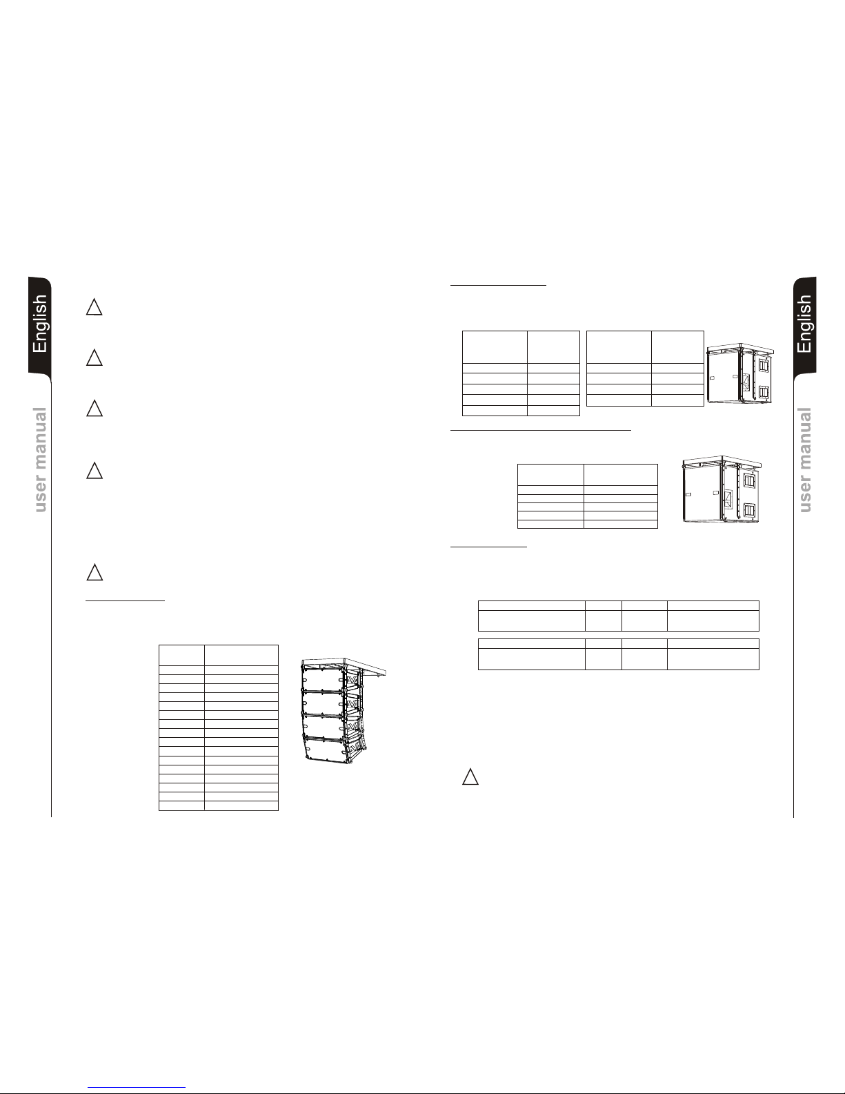
DVA T8 configuration
The DRK 10 flybar attests that the maximum number of DVA T8 is 16.
Refer to table 1 to determine the total weight borne by flybar according to the different
DVA T8 configurations.
Quantità Peso
[kg] [lbs.]
1 15 33
2 30 66
3 45 99
4 60 132
5 75 165
6 90 198
7 105 231
8 120 264
9 135 297
10 150 330
11 165 363
12 180 396
13 195 429
14 210 462
15 225 495
Table 1 16 240 528
WARNING
Make sure that the loudspeaker is securely installed in a stable position to avoid any
injuries or damages to persons or property.
Before hanging the loudspeaker check all the components for damages, deformations,
missing or damaged parts that may compromise safety during installation.
ATTENTION
The installation of the speaker on speaker stand must be carried out exclusively by
professionally qualified staff, being careful to place a speaker stand foot in the
direction of the output side of the sound (front side of the speaker) so as to maximize
stability in relation to the centre of gravity of the speaker (ref. page 58).
ATTENTION
When using the speaker with a pole mount for subwoofer (ref. page 59), in order to
avoid the danger of overturning and damage to people, animals and properties,
before proceeding with the installation of the system, check the allowed
configurations, the indications and the related requirements on the site of
dBTechnologies. However, make sure that the subwoofer which supports the speaker
is placed on a horizontal surface without inclinations.
CAUTION
TO REDUCE THE RISK OF ELECTRICAL SHOCK, GROUNDING OF THE
CENTER PIN OF THIS PLUG (POWERCON AC MAINS CONNECTOR) MUST BE
MAINTAINED
Table 2
Quantity x qty Configuration weight
DVA T8 8 120Kg
DVA S10dp (Neodymium woofer) 2 96Kg
Weight
Quantity x qty Configuration weight
DVA T8 12 180Kg
DVA S1518N (Neodymium woofer) 1 46Kg
Weight
216Kg
226Kg
!
Page 12
5
4
6
2
1
3
11
10
12
8
7
9
17
16
18
14
13
15
22
20
19
21
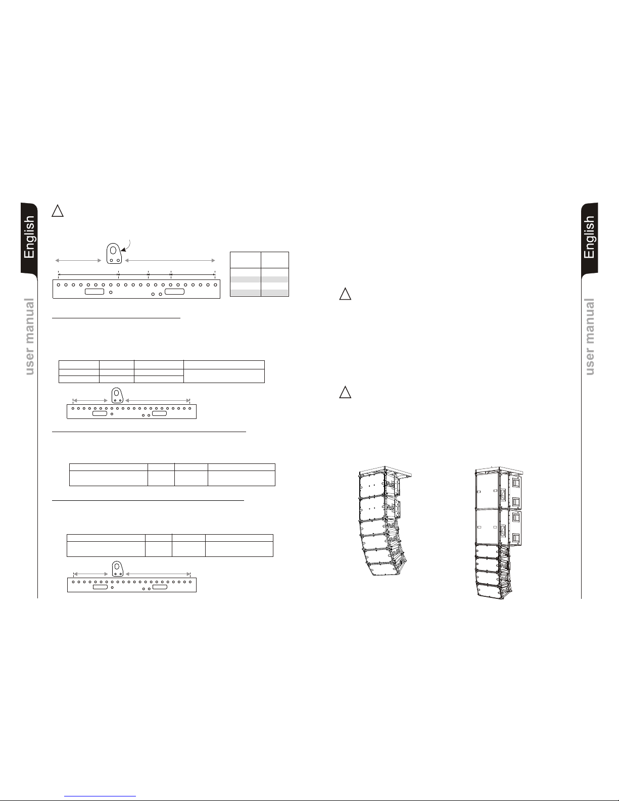
1200Kg
(12KN)
1000Kg
(10KN)
1300Kg
(13KN)
750Kg
(7.5KN)
Lifting hook Maximun
position load
1 - 9 1200kg
9 - 13 1300kg
13 - 16 1000kg
16 - 22 750kg
LIFTING HOOK
Mixed configuration with DVA T8 and DVA T12
The modular structure of DVA System permits mixed suspension configuration between
DVA T8 and DVA T12.
For this reason, it is necessary to calculate the total weight.
Example:
Quantity Weight x qty Configuration weight
DVA T12 10 300Kg
DVA T8 6 90Kg
390Kg
Mixed configuration with DVA T8 and DVA S1518N (Neodimium woofer)
The modular structure of DVA System permits mixed suspension configuration between
DVA T8 and DVA S1518N (Neodimium woofer).
For this reason, it is necessary to calculate the total weight.
Example:
Mixed configuration with DVA T8 and DVA S10dp (Neodimium woofer)
The modular structure of DVA System permits mixed suspension configuration between
DVA T8 and DVA S10dp (Neodymium woofer).
For this reason, it is necessary to calculate the total weight.
Example:
5
4
6
2
1
3
11
10
12
8
7
9
17
16
18
14
13
15
222019
21
5
4
6
2
1
3
11
10
12
8
7
9
17
16
18
14
13
15
22
20
19
21
22
Structural modification of flybar
Original parts dB Technologies
Note
Initiation and Operation
It is prohibited to make any changes to the structure of the flybar and on the stirrups
assembling of the speakers.
Tampering and/or modify the structure or the accessories may be causes risk of failure or
breakage.
It is forbidden to use parts and accessories other than those supplied.
Use only dB Technologies original parts.
Always install parts in accordance with these installation instruction!
Compile and store all DVA system documents in a safe place!
Warning
dB Technologies is not responsible for any possible damage to people, things and
animals if the security norms and total weight calculations are not observed!
During installation ensure that carrying structure of the system has added in the total
weight also the flybar weight, chain hoists, motors, cables and further weights.
§ 39, VBG 9a of the German employers' liability insurance association's accident
prevention regulations requires that load-carrying equipment be inspected by a qualified
expert and possible defects be eliminated prior to initial commissioning by the recipient.
§ 41 VBG 9a requires that load-carrying equipment be subjected to a non-routine
inspection following damage, repair work and other incidents that can affect load-carrying
capacity.
Warning
The safety regulations might be different in other countries. Please check with your
national safety authority the valid regulations!
EnglishEnglishEnglish
user manualuser manual
!
!
21
EnglishEnglishEnglish
user manualuser manual
!
WARNING! with particular attention the maximum load of point of attachment
of the lifting hook.
Failure to comply with all warnings may cause danger of structure and content falling
with potential damage to people, things and animals.
Observe
Quantity x qty Configuration weight
DVA T8 20 300Kg
DVA S1518N (Neodymium woofer) 4 184Kg
Weight
Quantity x qty Configuration weight
DVA T8 14 210Kg
DVA S10dp (Neodymium woofer) 4 192Kg
Weight
484Kg
402Kg
DVA T8
DVA T12
DVA T8
DVA S1518N
Page 13
100°
15°
DeutschDeutschDeutsch
BedienungsanleitungBedienungsanleitung
23
DeutschDeutschDeutsch
BedienungsanleitungBedienungsanleitung
24
BESCHREIBUNG
Die Versorgungsspannung des Verstärkers DIGIPRO® wurde für den Fullrange-Betrieb
ausgelegt. Dank der SMPS- Technologie (Switched-Mode Power Supplies) mit PFC
(Power Factor Correction) wird der Arbeitsbereich bei Versorgungsspannungen zwischen
100V AC und 240V AC gewährleistet, wobei die gleichen Ausgangsleistungen auch bei
schwankenden und nicht stabilisierten Versorgungsleitungen garantiert sind.
Der DVA T8 Lautsprecher ist mit Class-D Verstärker DIGIPRO ® G2-Serie ausgestattet.
Dieser Hochleistungsverstärker ermöglicht eine hohe Ausgangsleistungen bei
geringstem Gewicht und kompakten Abmessungen. Dank der sehr geringen
Verlustleistung erfolgt die Kühlung des Verstärkermoduls durch Konvektion, ohne Einsatz
eines Lüfters.
Das Verstärkermodul hat eine Leistung von 350W (RMS) für den Basslautsprecher,
175W (RMS) für den Mittenbereich und 175W (RMS) für die beiden 1“ Treiber.
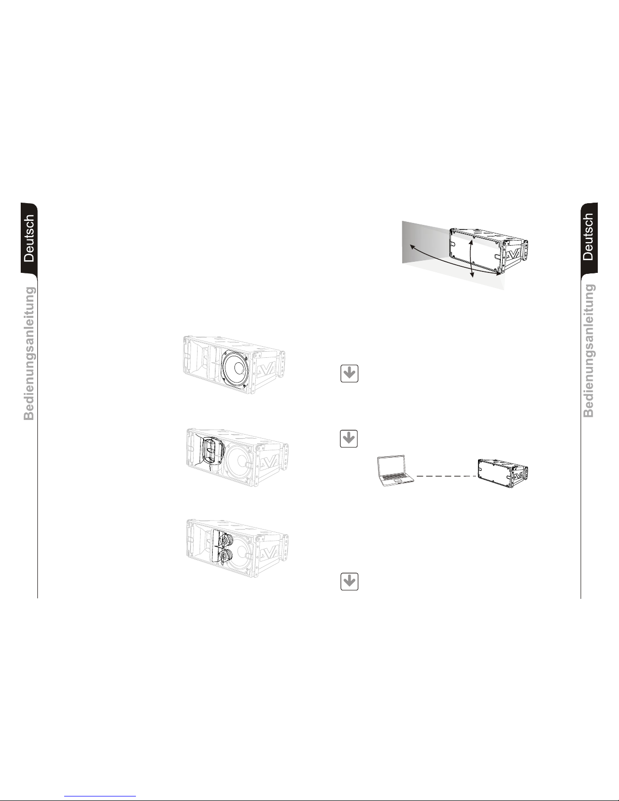
Im Bassbereich kommt ein 8" NeodymWoofer (Schwingspule 2.5") im
Bassreflexgehäuse zum Einsatz, der die
Wiedergabe ab 70 Hz erlaubt.
Der Mittenbereich besteht aus einem
6,5" Neodym-Woofern (Schwingspule
2"), der in einem eigenen Gehäuse
untergebracht ist und in ein Horn mit
Phase-Plug mündet. Der vor die
Membranen montierte Phase-Plug
vermeidet eine Überlagerung vertikaler
Phasenverläufe und sorgt für eine ArrayKopplung dank 3 Ausgangsslots, welche
die Richtwirkung erhöhen.
Das Horn verfügt über eine spezielle
Form, um eine gleichmäße Abstrahlung
und Ankopplung and das DVA T12 zu
ermöglichen.
Der Hochtonbereich ist mit zwei 1"
Neodym-Hochtontreibern
(Schwingspule 1.4") ausgestattet. Die
vertikale Anordnung optimiert die
Ankopplung und Reichweite der HochtFront.
Die Form des Horns wurde speziell
entwickelt, um eine korrekte Anbindung
mit den DVA T12 Modulen zu
ermöglichen.
Dank eines speziellen Designs konnte eine gleichmäßige und präzise Abstrahlung der
Lautsprecher von 100° in horizontaler Richtung und 15° in vertikaler Richtung erreicht
werden.
DVA Network
DVA T8 ist mit einer dedizierten proprietären, als RDNET bezeichneten
Netzschnittstelle ausgestattet, dank der es über ein Interface (RDNET Control) an
einen Computer angeschlossen werden können.
Hierzu wurde ein Kommunikationsprotokoll entwickelt, mit dem die Daten empfangen und
gesendet werden. Dank dieser Verbindung können die Lautsprecherparameter, wie
Ausgangsleistung, Verstärkertemperatur, Limiterstatus usw. in Echtzeit kontrolliert
werden.
Außerdem können verschiedene Entzerrungen ausgewählt bzw. neue erstellt werden
oder die gewünschte Lautstärke eingestellt werden.
DVA USB Manager
Die Firmware des Verstärkermoduls kann über den USB-Anschluss aktualisiert werden.
Um diesen Vorgang zu ermöglichen und zu vereinfachen, wurde ein dediziertes
Programm entwickelt, das beim Hersteller angefordert und auf einen Computer installiert
werden muss.
Wir empfehlen, die Software DVA_Network direkt von der Webseite dB
Technologies (www.dbtechnologies.com) im Abschnitt «software &
Controller» herunterzuladen
Wir empfehlen, die Software DVA USB Manager direkt von der Webseite dB
Technologies (www.dbtechnologies.com) im Abschnitt «software &
Controller» herunterzuladen
DVA Composer Akustiksimulation für Systeme der Serie DVA
DVA Composer ist eine Software zur Beschallungsplanung und simulation für alle Line
Array-Modelle der Serie DVA und den zugehörigen Subwoofern.
Sie ermöglicht die Verwaltung eines Stereosystems, das aus Line Arrays und Subwoofern
besteht, wobei das akustische Ansprechprofil jeweils separat simuliert wird.
Dem Nutzer werden eine Reihe von Daten geliefert, z.B. die Phasenanpassung zwischen
den Hängesystemen und den entsprechenden Subwoofern am Boden. Außerdem
werden die optimalen Winkel zwischen den Line Array-Modulen und den entsprechenden
Equalizer-Presets angegeben, so dass auch weniger erfahrene Benutzer die Leistungen
des Systems optimieren können.
Wir empfehlen, die Software DVA_Composer direkt von der Webseite dB
Technologies (www.dbtechnologies.com) im Abschnitt «software &
Controller» herunterzuladen
PC
DOWNLOAD
DOWNLOAD
DOWNLOAD
Page 14
DeutschDeutschDeutsch
BedienungsanleitungBedienungsanleitung
25
DeutschDeutschDeutsch
BedienungsanleitungBedienungsanleitung
26
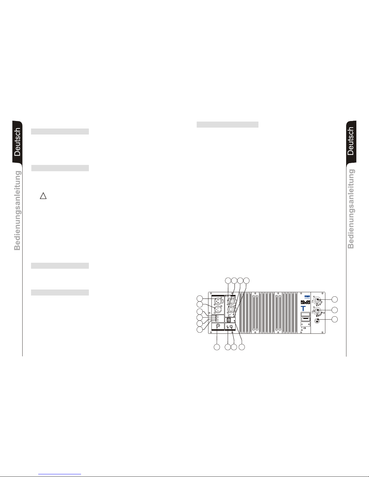
BEDIENELEMENTE UND FUNKTIONEN
Abschnitt “Balanced Audio”
1) EINGANGSBUCHSE "INPUT”
Symmetrischer XLR Eingang für Line-Pegel.
2) AUSGANGSBUCHSE "LINK”
Der parallel zum Eingang (1) angeschlossene XLR-Anschluss kann dazu
verwendet werden, das ankommende Audiosignal an einen anderen verstärkten
Lautsprecher weiter zu leiten.
Abschnitt “Status”
3) LED “LIMITER”
Diese rote LED leuchtet auf, um das Ansprechen der Limiterschaltung zu
signalisieren, die die Verzerrung des Verstärkers verhindert und die Lautsprecher
gegen Überlast schützt.
4) LED “SIGNAL”
Diese LED leuchtet grün, wenn das Audiosignal anliegt mit einem Pegel von größer
-20dBu.
5) LED “MUTE/PROT”
Diese gelbe LED zeigt den Zustand des Verstärkers an. Während des normalen
Betriebs ist die LED ausgeschaltet; wenn sie blinkt oder ständig leuchtet, kann man
der Diagnosetabelle Informationen zur Kontrolle des Zustands des Verstärkers
entnehmen.
6) LED “READY”
Diese LED leuchtet grün, wenn das Gerät an die richtige Netzspannung
angeschlossen ist. Während des normalen Betriebs ist die LED eingeschaltet;
wenn sie blinkt oder ausgeschaltet ist, kann man der Diagnosetabelle
Informationen zur Kontrolle des Zustands des Verstärkers entnehmen.
Abschnitt “Input control”
7) EMPFINDLICHKEITSREGLER EINGANG “INPUT SENS”
Dieser Regler dient zum Einstellen der Eingangs-Empfindlichkeit des Verstärkers .
Diese Regelung beeinflusst nicht den Ausgangspegel “LINK”.
Abschnitt “RDNET”
8) EINGANGSSTECKER "DATA INPUT”
RJ45-Stecker für den Dateneingang.
9) AUSGANGSSTECKER "DATA LINK”
RJ45-Stecker Datenausgang für die Kaskadenschaltung.
10) LED “LINK”
Diese grüne Leuchte schaltet sich nur ein, wenn der Verstärker die Daten
erkannt hat und über den Computer mit der Haupteinheit RDNET verbunden ist.
11) LED “ACTIVE”
Diese gelbe Leuchtet blinkt, wenn eine Datenübertragung zwischen RDNET und
Verstärkermodul im Gange ist.
Vermeiden Sie den Dauerhaften Betrieb im Limit
Abschnitt “DSP configuration”
12) LED “Remote Preset Active”
Diese gelbe Leuchte zeigt den Ausschluss der Lautsprechersteuerung und des
Drehschalters “DSP Preset” (13), wenn der Verstärker per RDNET durch einen
Computer ferngesteuert wird.
Die Leuchte blinkt langsam, wenn sich der Drehschalter auf Position 9 befindet
und eine vorher gespeicherte benutzerdefinierte Entzerrung gespeichert wurde.
13) DREHSCHALTER mit 10 Positionen “DSP Preset”
Über diesen Drehschalter mit 10 Positionen können die vorgesehenen neun
Entzerrungskurven (Schalter 0-8) ausgewählt oder eine vorher per RDNET vom
Benutzer gespeicherte Entzerrung aufgerufen werden (Schalter 9).
Falls diese Option nicht verwendet wird, entspricht die Entzerrung 9 der
Entzerrung 0.
Zur Erläuterung der Entzerrungskurven siehe die Tabelle.
14) STECKER “Service Data USB”
Über diesen USB-Stecker kann die Firmware des DVA T8 Verstärkermoduls über
einen Computer und ein eigenes Programm aktualisiert werden.
15) EINBAUSTECKER “MAINS INPUT”
Für den Anschluss des beiliegenden Netzkabels.
Für den Netzanschluss wird ein POWER CON® (blau)Stecker verwendet.
16) EINBAUKUPPLUNG FÜR DIE POWER-WEITERLEITUNG “MAINS OUTPUT
LINK”
Er dient zum Durchschleifen der Netzspannung. Der Ausgang ist parallel an den
Eingang (15) angeschlossen und kann zum Speisen eines weiteren verstärkten
Lautsprechers verwendet werden. Einbaukupplung POWER CON® (grau).
17) SICHERUNGSHALTER “MAINS FUSE”
Er enthält die Netzsicherung.
!!
7
15
16
17
Made in Italy
Input
Link
Audio
Input Sens
READY
MUTE/PROT
SIGNAL
LIMITER
0dB
+10dB
+4dB
1 = GND
2 = HOT
3 = COLD
1
0
2
3
4
5
6
7
8
9
Active
Data
Link
Link
Active
Data
Input
Input Control
Balanced Audio
Status
Service
Data
User
Remote
Preset
DSP Configuration
SERIAL N.
“CAUTION”
RISK OF ELECTRICAL SHOCK
DO NOT OPEN
“AVIS”
RISQUE DE CHOCH ELECTRIQUE
NE PAS OUVRIR
dd
BB
TECHNOLOGIESTECHNOLOGIES
(REPLACE FUSE WITH SAME RATINGS)
MAINS
FUSE
220-240V~
(18Amax)
3680Wmax
100-120V~
(16Amax)
1320Wmax
100-120V~
4Amax
MAINS
LINK
MAINS
INPUT
FULL RANGE
ACTIVE P.F.C.
100-240V~ 50-60Hz
Digital Vertical Array
8
220-240V~
2Amax
220-240V~
(T3,15A L 250V~)
100-120V~
(T6,3A L 250V~)
PUSH
PUSH
PUSH
1
2
6
5
4
3
11
10
98
14
13
12
L177007324
REV SW 2.32
Page 15
DeutschDeutschDeutsch
BedienungsanleitungBedienungsanleitung
27
DeutschDeutschDeutsch
BedienungsanleitungBedienungsanleitung
28
MERKMALE UND SCHUTZ
Frontverkleidung
Angesichts des professionellen Einsatzes dieser Lautsprecher sind
dieLautsprecherkomponenten durch ein Lochblech mit 1,2 Stärke hinterlegtem
Schaumstoff geschützt.
IPOS (Intelligent Power-On Sequence)
Netzanschluss
Jeder Aktivlautsprecher hat ein eigenes Netzkabel. Der Anschluss erfolgt mit einem
Netzstecker Neutrik POWER CON® (blau), der den einfachen und schnellen Anschluss
des Lautsprechers erlaubt und eine sichere Verriegelung garantiert. Der Stecker dient
zugleich als Schalter zum Einschalten und Ausschalten der Lautsprecher.
Das Gerät muss an ein Netz angeschlossen werden, dass die verlangte maximale Leistung
abgeben kann.
Power-Weiterführung
Auf der Rückseite des Lautsprechers befindet sich eine Einbaukupplung Neutrik POWER
CON® (grau) für die Weiterleitung der Netzstromversorgung.
Über diese Steckbuchse kann man einen anderen Lautsprecher anschließen, um die
Anzahl der direkten Netzanschlüsse zu reduzieren. Die maximale Stromaufnahme der
Verstärker ist auf ihrem Typenschild angegeben. Die Anzahl, der maximal aneinander
anschließbaren Lautsprecher ist abhängig von ihrer maximalen Stromaufnahme und vom
maximalem Bemessungsstrom der ersten Netzsteckdose.
Kühlung
Die Temperaturkontrolle wird durch einen zentralen Mikroprozessor (main) gesteuert, der
mit den lokalen Mikroprozessoren (Verstärker und Netzteil) interagiert und die Daten an
den DSP weiterleitet, um eventuelle Korrekturen durchzuführen.
Bei einer Überhitzung des Verstärkermoduls wird die Lautstärke schrittweise um jeweils
0,1dB verringert, bis sich eine Temperaturstabilisierung einstellt.
Nachdem die normale Betriebstemperatur erreicht wurde, wird die Lautstärke automatisch
wiederhergestellt.
Einschaltung
Die ordnungsgemäße Einschaltung des Lautsprechers wird durch eine
Initialisierungsprozedur garantiert, während der das Modul durch ein Hilfsnetzteil gespeist
wird.Wenn alle Peripheriegeräte des Verstärkers korrekt erfasst wurden, wird das
Hauptnetzteil eingeschaltet.
Die Funktion sorgt vor der Einschaltung des HauptPSU (Power Supply Unit) bei jedem Modul für eine zufällige und differenzierte Verzögerung.
Dadurch wird verhindert, dass der Anlaufstrom sich bei der Einschaltung der
verschiedenen Module bündelt und die AC-Versorgungsleitung überlastet.
Nach Beendigung des Startvorgangs leuchtet am Verstärkermodul nur die grüne LED
“READY” auf.
Störungsanzeigen und Schutzvorrichtungen
Der Mikroprozessor ist in der Lage drei verschiedene Arten von Störungen durch das
Blinken der roten LED “LIMITER” auf dem Bedienfeld des Verstärkers vor dem Aufleuchten
der grünen LED “READY” anzuzeigen. Bei den drei Störungsarten handelt es sich um:
1) ACHTUNG: Es wurde ein leichter Fehler oder eine leichte Funktionsstörung mit
automatischer Rücksetzung festgestellt und die Leistungen des Verteilers werden
nicht eingeschränkt.
2) BEGRENZUNG: Bei Ermittlung einer Störung werden die Leistungen des
Lautsprechers reduziert. Der Schallpegel wird verringert bzw. einer oder mehr
Verstärker werden deaktiviert. Dieser Zustand kann sich teilweise auf die korrekte
Betriebsweise des Lautsprechers auswirken.
Falls das Problem auch bei einem späteren Gebrauch des Moduls weiterhin besteht,
muss der Kundendienst eingeschaltet werden, um die Störung zu beheben.
3) DEFEKT: Es wurde eine schwere Funktionsstörung festgestellt. Der Verteiler wird in
den Status “Mute” geschaltet.
Im Störungsfall sollte man vor der Benachrichtigung des Kundendienstes das Modul
zunächst aus- und erneut einschalten, um zu überprüfen, ob das Problem nach wie vor
vorhanden ist.
ZUSTAND DES LED LED LED LED MODULFUNKTIONEN
MODULS «READY» «MUTE/PROT» «SIGNAL» «LIMIT»
Einschaltvorgang AUS EIN für 5 sec. AUS AUS Audio in MUTE
Initialisierung des Verstärkermoduls
Normalbetrieb EIN AUS Normalbetrieb Normalbetrieb Audio EIN
Initialisierung des Moduls erfolgreich durchgeführt
Partialfehler EIN Zyklisches Blinken Normalbetrieb Normalbetrieb Audio EIN
Das Modul hat eine teilweise Störung ermittelt und
bleibt mit eingeschränkter Betriebsweise aktiviert
Gesamtfehler AUS EIN AUS Zyklisches Blinken Audio in MUTE
Das Modul hat eine schwere Störung ermittelt
und bleibt im Schutzmodus
Temperatur Steuerung:
Erste thermische EIN Zyklisches Blinken Normalbetrieb Normalbetrieb Audio EIN
Schwelle (1 Langsame Blinkzeichen) Der Verstärker verringert den Pegel in 0.1dB-Schritten
bis zu einem Maximum von -3dB
Zweite thermische EIN Zyklisches Blinken Normalbetrieb Normalbetrieb Audio EIN
Schwelle (2 schnelle Blinkzeichen) Der Verstärker verringert den Pegel von -3dB in
Schritten von 0.1Db zu Maximum von -6dB
*) Anmerkung: Die Temperaturen, die über RDnet Software angezeigt werden, beziehen sich auf die tatsächlichen Temperaturen der Halbleiter und nicht z.B auf zugängliche Bauteile wie Kühlrippen der
Rückseite
DIAGNOSETABELLE
ZUSTAND DES MODULFUNKTIONEN
MODULS
AUS Das Modul befindet sich im Normalbetrieb
Die Lautstärke (INPUT SENS) und der Drehschalter (DSP
Preset) sind aktiviert.
EIN Zyklisches Blinken Das Verstärkermodul wird über RDNET ferngesteuert.
Die Lautstärke (INPUT SENS) und der Drehschalter (DSP
Preset) werden übersprungen
Entzerrung «USER Eq» Zyklisches Blinken Das Modul befindet sich im Normalbetrieb.
(Drehschalter «DSP Preset» Es wird eine per RDNET gespeicherte Entzerrung verwendet.
auf Position 9)
LED LED LED
« » «LINK» «ACTIVE»
RDNET nich akiv AUS AUS
RDNET verbunden EIN
AUS AUS
Remote Preset Active
Page 16
DeutschDeutschDeutsch
BedienungsanleitungBedienungsanleitung
29
EMV Einstufung
Entsprechend der Norm EN 55103 ist diese Gerät entwickelt um inE3 (oder E2, E1)
elektromagnetischen Umgebungen zu arbeiten.
TECHNISCHE DATEN
System Active 3-Amps
Verstärker typ Digital - Class D
DIGIPRO G2 technology
RMS Leistung 700W
(LF) RMS 175W
(MF) RMS 175W
(HF) RMS 300W
Musikleistung 1400W
Frequenzgang (-6dB) 66-18.000Hz
Frequenzgang (-10dB) 61-19.900Hz
Crossover MF-H 1900Hz
24dB/Oct
Crossover LF-MF 400Hz
24dB/Oct
Schalldruck (SPL) 132dB max
Lautsprecher 1 woofer 8" - VC 2.5" - Neodymium
2 midrange 6,5" - VC 2" - Neodymium
3 compression driver 1" - VC 1.4" - Neodymiun
Empfindlich keit Eingang 0dBu
Impedanz Eingang
Symmetrisch 20Kohm
Unsymmetrisch 10Kohm
Netzspannung Full-range mit PFC und SMPS
100-240V~ 50-60Hz
Einschaltstrom 3,3A
Abmessungen (BxHxT) 580x386x327mm
(23,2x9,6x13,08 inch.)
Gewicht 14,2Kg
(31,3lbs)
DSP PROZESSOR
DSP Analog Device 56 bits
Sampling 24 bit / 96kHz S/N=114dB
Lautstärke Kontrolle Digital
Presets 9 preset EQU
Mechanik
Laufsprechergehäuse (PP) Kunststoff
Interne Verstärkung Stahl
Flugvorrichtungl Stahl
Winkel 0° - 1,5° - 3° - 4,5° - 6° - 8° - 10° - 12,5° - 15°
Laufsprecherform Trapezförmig - Winkel 15°
Griffe 1 x einer pro Seite
Frontverkleidung 1,2mm Stärke hinterlegtem Schaumstoff
geschützt
®
DRK 10
Das DVA System erhielt die TÜV- Prüfung für DVA T4, DVA T8, DVA T12, DVA S09dp,
DVA S10dp, DVA S1518N und DVA S2585N Lautsprecher in Kombination mit DRK 10
Flugrahmen das maximal zulässige Gewicht 250 kg.
DVA T8 Konfiguration
Es dürfen maximal 16 DVA T8 Topteile an einem DRK 10 Flugrahmen befestigt werden.
Entsprechend Tabelle 1 bestimmen sie das Gesamtgewicht und Belastung des DRK 10
Flugrahmens verschiedener DVA T8 Konfigurationen
Anzahl Gewicht
[kg] [lbs.]
1 15 33
2 30 66
3 45 99
4 60 132
5 75 165
6 90 198
7 105 231
8 120 264
9 135 297
10 150 330
11 165 363
12 180 396
13 195 429
14 210 462
15 225 495
Tabelle 1 16 240 528
INSTALLATION
( ).
ACHTUNG
Den Lautsprecher auf eine stabile und sichere Art und Weise installieren, um jede
Gefahr für Personen oder Sachschäden zu vermeiden.
Bevor man den Lautsprecher aufhängt, alle Teile kontrollieren, sie sollen keine Schäden
oder Verformungen, keine fehlenden oder beschädigten Teile haben, die eine sichere
Installation beeinträchtigen könnten.
ACHTUNG
Die Benutzung des Lautsprechers mit Ständer und Topplatte darf nur durch
qualifiziertes Fachpersonal erfolgen. Hierbei ist darauf zu achten, dass ein Fuß des
Ständers in Richtung der Schallseite (Vorderseite des Lautsprechers) positioniert
ist, um die höchste Stabilität in Bezug auf den Schwerpunkt des Lautsprechers zu
erreichen siehe Seite 58
ACHTUNG
Bei der Verwendung des Lautsprechers mit Hochständer für Subwoofer (Pole
Mount – siehe Seite 59) muss man, um eine Gefahr des Umkippens bzw. von
Personen- oder Sachschäden zu vermeiden, vor der Installation des Systems auf
der Homepage von dBTechnologies die zulässigen Konfigurationen, sowie die
entsprechenden Hinweise und Vorgaben überprüfen. In jedem Fall ist darauf zu
achten, dass der Subwoofer unter dem Lautsprecher auf einer horizontalen, frei
von Neigungen.
GEFAHR! Die zulässige Last in Bezug auf den Anschlusspunkt des Hubhakens
muss genau beachtet werden. Werden diese Warnhinweise nicht beachtet, kann die
Struktur und ihr Inhalt herunterfallen, was Schäden an Personen, Tieren und
Gegenständen verursachen kann.
!
!
!
!
DeutschDeutschDeutsch
BedienungsanleitungBedienungsanleitung
30
Page 17
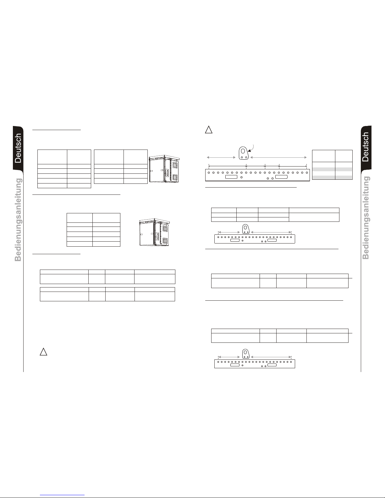
DVA S1518N Konfigurationen (Neodymium woofer)
Es dürfen maximal 5 DVA S1518N Subwoofer mit Neodymium woofer order einem
DRK 10 Flugrahmen befestigt werden. Entsprechend Tabelle 3 bestimmen sie das
Gesamtgewicht und Belastung des DRK 10 Flugrahmens verschiedener DVA S1518N
Konfigurationen
Anzahl Gewicht
DVA S10dp [kg] [lbs]
(Neodymium woofer)
1 48 106
2 96 212
3 144 317
4 192 423
5 240 528
Anzanhl Gewicht
DVA S10dp [kg] [lbs]
(Ceramic woofer)
1 54 119
2 108 238
3 162 357
4 216 476
Tabelle 2
DRK 20
Die Vorrichtung Fly Bar DRK 20 und die entsprechenden Flugrahmensysteme für die
Lautsprecher DVA T4, DVA T8, DVA T12, DVA S09dp, DVA S10dp, DVA S1518N und
DVA S2585N, wurden entwickelt und mit technischen Bruchtests geprüft, entsprechend
der Vorgaben des Italienischen Ministerialdekrets D.M. vom 14.01.2008 „Neue
technische Richtlinien für den Bau“ und, in Bezug auf die Stahlstrukturen, entsprechend
„Eurocode 1“ und „Eurocode 3“.
Das System wurde technisch geprüft und entsprechend der Werte der maximalen
Tragkraft, die in der Konformitätserklärung, die von CERMET ausgestellt wurde, Nr. Reg.
PA 68913 V 00001 2011, als konform bescheinigt.
DRK 20 darf nur von qualifiziertem Personal benutzt werden!
Die strukturellen Berechnungen bescheinigen, dass das maximal anwendbare Gewicht
am flybar DRK20 vom Anschlusspunkt des Hubhakens abhängt. Für das Detail finden Sie
im Handbuch gewidmet
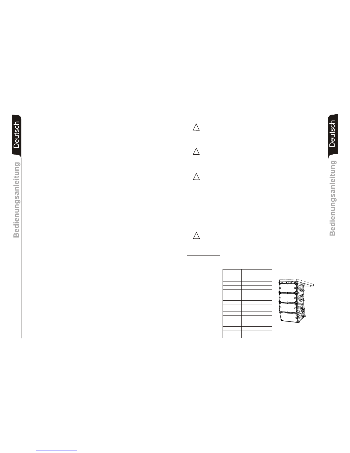
Gemischte Konfigurationen
Die mechanische Konstruktion des DVA Systems erlaubt eine gemischte Konfiguration.
Aus diesem Grund ist es notwendig, das Gesamtgewicht entsprechend der
unterschiedlichen Konfigurationen zu bestimmen.
DVA S10dp Konfigurationen
Es dürfen maximal 5 S10dp Subwoofer mit Neodimium woofer order es dürfen maximal 4
S10dp Subwooferan mit Ceramic woofer einem DRK 10 Flugrahmen befestigt werden.
Entsprechend Tabelle 2 bestimmen sie das Gesamtgewicht und Belastung des DRK 10
Flugrahmens verschiedener DVA S10dp Konfigurationen
Anzahl Gewicht
[kg] [lbs]
1 48 106
2 96 212
3 144 317
4 192 423
5 240 528
Tabelle 3
x Konfigurationen
DVA T8 8 120Kg
DVA S10dp (Neodymium woofer) 2 96Kg
Anzahl Gewicht Anzahl Gewicht
x Konfigurationen
DVA T8 12 180Kg
DVA S1518N (Neodymium woofer) 1 46Kg
Anzahl Gewicht Anzahl Gewicht
216Kg
226Kg
!
GEFAHR! Die zulässige Last in Bezug auf den Anschlusspunkt des Hubhakens
muss genau beachtet werden. Werden diese Warnhinweise nicht beachtet, kann die
Struktur und ihr Inhalt herunterfallen, was Schäden an Personen, Tieren und
Gegenständen verursachen kann.
!
5
4
6
2
1
3
11
10
12
8
7
9
17
16
18
14
13
15
22
20
19
21
1200Kg
(12KN)
1000Kg
(10KN)
1300Kg
(13KN)
750Kg
(7.5KN)
1 - 9 1200kg
9 - 13 1300kg
13 - 16 1000kg
16 - 22 750kg
HUBHAKENS
Position des
Anschlusspunktes
des Hubhakens
Zulässige
Tragkraft
Gemischte Konfigurationen mit DVA T8 und DVA T12
Die mechanische Konstruktion des DVA Systems erlaubt eine gemischte Konfiguration
zwischen DVA T8 und DVA T12. Aus diesem Grund ist es notwendig, das Gesamtgewicht
entsprechend der unterschiedlichen Konfigurationen zu bestimmen.
Beispiele:
x Konfigurationen
DVA T12 10 300Kg
DVA T8 6 90Kg
Anzahl Gewicht Anzahl Gewicht
390Kg
5
4
6
2
1
3
11
10
12
8
7
9
17
16
18
14
13
15
222019
21
Gemischte Konfigurationen mit DVA T8 und DVA S10dp (Neodymium woofer)
Die mechanische Konstruktion des DVA Systems erlaubt eine gemischte Konfiguration
zwischen DVA T8 und DVA S10dp. Aus diesem Grund ist es notwendig, das
Gesamtgewicht entsprechend der unterschiedlichen Konfigurationen zu bestimmen.
Beispiele:
5
4
6
2
1
3
11
10
12
8
7
9
17
16
18
14
13
15
222019
21
Gemischte Konfigurationen mit DVA T8 und DVA S1518N (Neodyminum woofer)
Die mechanische Konstruktion des DVA Systems erlaubt eine gemischte Konfiguration
zwischen DVA T8 und DVA S1518N. Aus diesem Grund ist es notwendig, das
Gesamtgewicht entsprechend der unterschiedlichen Konfigurationen zu bestimmen.
Beispiele:
Quantity x Konfigurationen
DVA T8 14 210Kg
DVA S10dp (Neodymium woofer) 4 192Kg
Gewicht Anzahl Gewicht
402Kg
Quantity x Konfigurationen
DVA T8 20 300Kg
DVA S1518N (Neodymium woofer) 4 184Kg
Gewicht Anzahl Gewicht
484Kg
DeutschDeutschDeutsch
BedienungsanleitungBedienungsanleitung
31
DeutschDeutschDeutsch
BedienungsanleitungBedienungsanleitung
32
Page 18
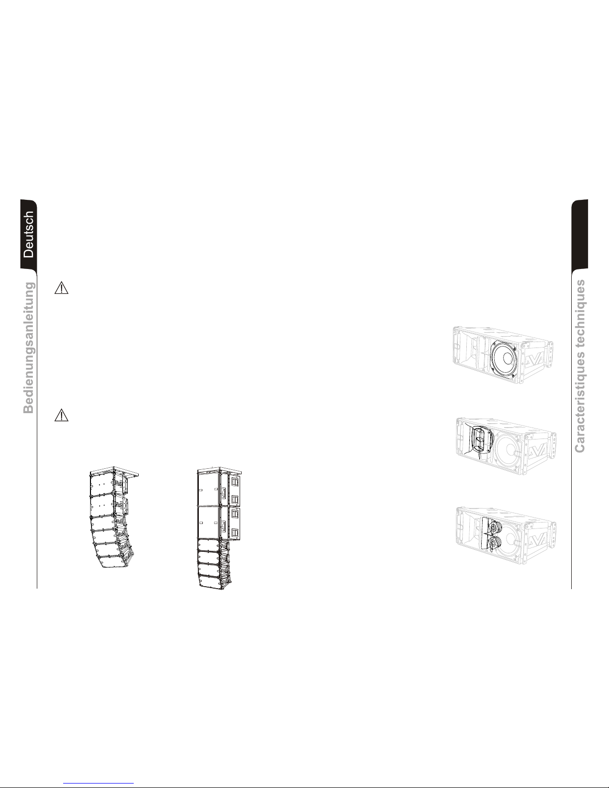
Caracteristiques techniquesCaracteristiques techniques
Français
34
DESCRIPTION
Le diffuseur DVA T8 est équipés d'un tri-amplification en classe D de la série
DIGIPRO®G2.
Cet amplificateur, de très haute efficacité, permet d'obtenir des puissances de sorties
élevées avec des poids et encombrements réduits. Grâce à la basse puissance dissipée,
le refroidissement du module amplificateur se fait de manière statique évitant l'utilisation
de ventilateur.
Le circuit d'alimentation de l'amplificateur DIGIPRO® G2 a été conçu pour fonctionner en
modalité full-range ; grâce à la technologie SMPS (Switched-Mode Power Supplies) avec
PFC (Power Factor Correction), le fonctionnement à tensions d'alimentations de 100Vac
à 240Vac, assurant les mêmes prestations acoustiques même avec des lignes
d'alimentation fluctuantes et non stabilisées.
Le module amplificateur est en mesure d'affecter 350W (RMS) pour la section des basses,
175W (RMS) pour la section des moyennes et 175W (RMS) pour la section autres.
La section des basses pilote un woofer
8" au néodyme (voice coil 2.5").
Cette configuration garantit un niveau
de pression acoustique élevé, et
l'atteinte de fréquences jusqu'à 70Hz.
La section des moyennes pilote une
midrange, de 6,5" au néodyme (voice coil
2"), logés dans leur propre chambre
acoustique, et chargés en pavillon avec
compensateur de phase. Les phases
plug montées devant les cônes évitent
les superpositions de phases verticales
en créant de fait un array local à 3 slots
en sortie, qui en augmentent la directivité.
Le design du pavillon a été
expressément conçu pour le couplage
correct avec les modules DVA T4 and
DVA T12.
La section autres pilote deux driver de 1"
au néodyme (voice coil 1.4") montés
verticalement et mis à distance pour
optimiser la couverture verticale.
Le design du pavillon a été
expressément conçu pour le couplage
correct avec les modules DVA T4 and
DVA T12.
Strukturelle Änderungen am Flugrahmen flybar
Es ist absolut verboten, irgend eine Änderung an der Struktur und der entsprechenden
Bügel vorzunehmen, die mit den Lautsprechern geliefert werden.
Manipulierungen und/oder Änderungen an der Struktur oder am mitgelieferten Zubehör,
können Zerstörungen oder Brüche verursachen.
Original-Zubehör dBTechnologies
Es ist verboten, Teile und Zubehöre zu benutzen, die anders sind, als die mitgelieferten.
Nur Original-Teile von dBTechnologies verwenden.
Jede Installation oder Benutzung der gelieferten Teile muss entsprechend der
mitgelieferten Montageanleitung ausgeführt werden.
Alle Unterlagen des Systems DVA müssen an einem sicheren Ort aufbewahrt werden!
Achtung
dB Technologies ist nicht für Schäden an Personen, Gegenständen oder an
Tieren verantwortlich, wenn die Sicherheitsvorschriften und die Berechnung der
maximalen Gewichte nicht eingehalten wurden!
Anmerkungen
Während der Installation sicherstellen, dass in der tragenden Struktur des Systems, in der
Berechnung des Gesamtgewichts, auch das Gewicht des DRK, der Hubketten, der
Motoren, der Kabel und der zusätzlichen Gewichte berücksichtigt wurde.
Beginn und Funktionsweise
Der § 39, VBG 9a über die obligatorische Versicherung durch deutsche Arbeitgeber in
Bezug auf die Unfallverhütung schreibt vor, dass die Ausstattung des Flugrahmens durch
qualifiziertes Fachpersonal überprüft werden muss und dass mögliche Defekte vor der
Auslieferung an den Endbenutzer behoben werden müssen.
Der § 41 VBG 9a schreibt vor, dass die Ausstattung des Flugrahmens einer
außergewöhnlichen Wartung unterzogen werden muss, wenn Schäden, Reparaturen
und andere Unfälle aufgetreten sind, welche Auswirkungen auf die Leistungsfähigkeit
des Flugrahmens haben könnten.
Achtung
Die Sicherheitsvorschriften können je nach Zielland anders sein. Der Benutzer ist
verpflichtet, die Sicherheitsvorschriften und Gesetze des Landes zu prüfen, in dem
das Produkt benutzt wird!
DeutschDeutschDeutsch
BedienungsanleitungBedienungsanleitung
33
DVA T8
DVA T12
DVA T8
DVA S1518N
Page 19
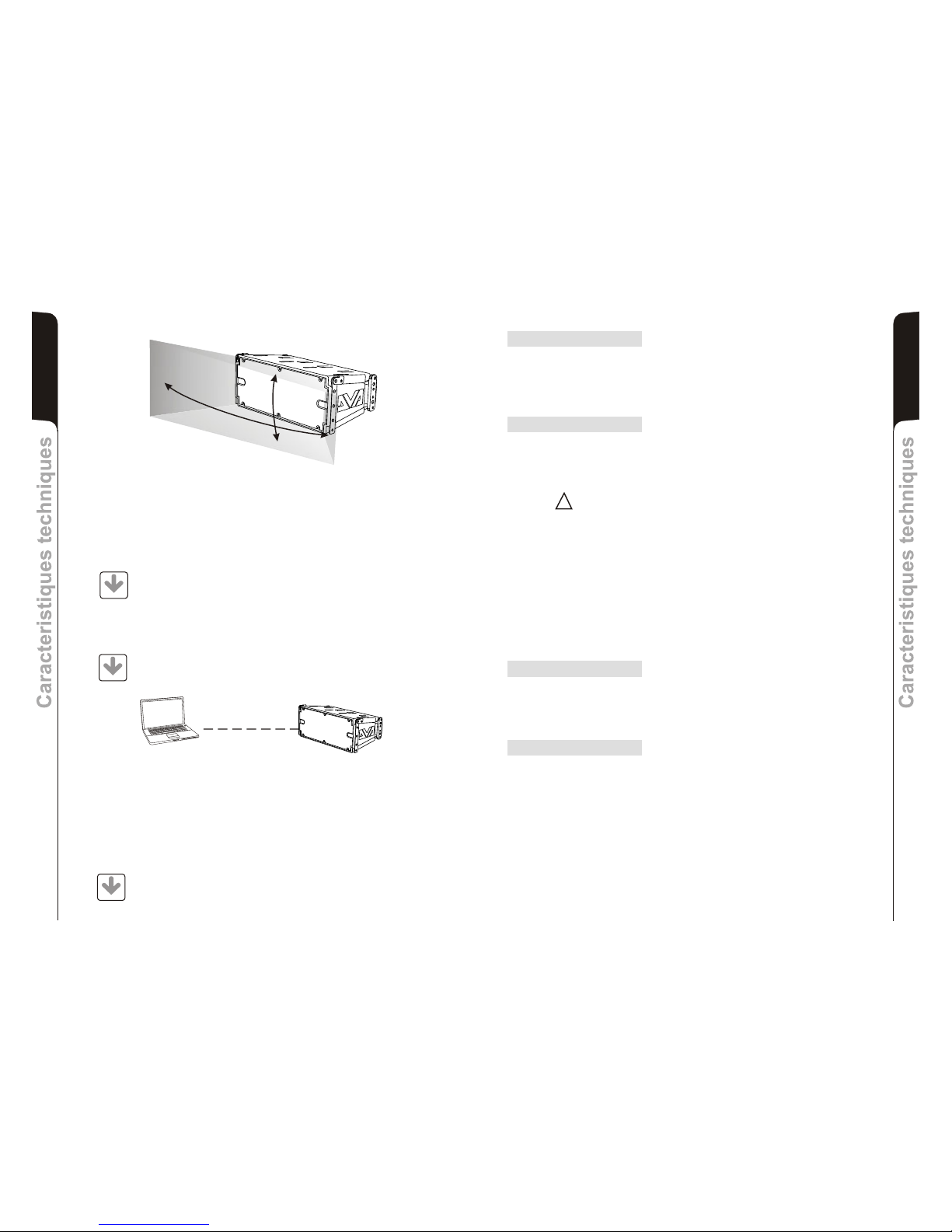
Une élaboration ciblée a permis d'atteindre une couverture constante et précise de 100°
dans le sens horizontal et 15° dans le sens vertical pour chaque diffuseur.
Français
Caracteristiques techniquesCaracteristiques techniques
35
Caracteristiques techniquesCaracteristiques techniques
Français
36
100°
15°
COMMANDES ET FONCTIONS
Section “Balanced Audio”
1) CONNECTEUR D'ENTRÉE “INPUT”
Entrée symétrique au niveau ligne . Elle peut accueillir des prises “XLR”.
2) CONNECTEUR DE SORTIE “LINK ”
Le connecteur “XLR” connecté en parallèle avec l'entrée (1) peut être utilisé pour
envoyer le signal audio en entrée d'une autre enceinte amplifiée.
Section “Status”
3) INDICATEUR LUMINEUX “LIMITER”
Cet indicateur s'allume de couleur rouge pour indiquer l'intervention du circuit
limiteur interne qui évite la distorsion de l'amplificateur et protège les haut-parleurs
contre les surcharges
Toujours éviter les conditions d'exploitation où le système fonctionne pendant
de longues périodes de temps avec la LED clignote ou il est toujours ON
4) INDICATEUR LUMINEUX “SIGNAL”
Cet indicateur s'allume de couleur verte pour indiquer la présence du signal audio à
un niveau supérieur de -20dBu.
5) INDICATEUR LUMINEUX “MUTE/PROT”
Cet indicateur de couleur jaune indique l'état de l'amplificateur. Pendant le
fonctionnement normal, la LED est éteinte; si elle clignote ou si elle reste allumée
fixe, se référer au tableau de diagnostic pour contrôler l'état de l'amplificateur..
6) INDICATEUR LUMINEUX “READY”
Cet indicateur s'allume de couleur verte pour indiquer que la tension d'alimentation
de réseau est correcte. Pendant le fonctionnement normal, la LED est allumée; si
elle clignote ou si elle est éteinte, se référer au tableau de diagnostic pour contrôler
l'état de l'amplificateur.
Section “Input control”
7) CONTRÔLE SENSIBILITÉ ENTRÉE “INPUT SENS”
Ce contrôle règle la sensibilité du signal en entrée à l'amplificateur.
Ce contrôle n'influence pas le niveau de la sortie “LINK” (2)
Section “RDNET”
8) CONNECTEUR D'ENTRÉE "DATA INPUT”
Connecteur RJ45 d'entrée des données.
9) CONNECTEUR DE SORTIE "DATA LINK”
Connecteur RJ45 de sortie des données par le branchement série en cascade.
10) INDICATEUR LUMINEUX “LINK”
Cet indicateur de couleur verte s'allume uniquement quand l'amplificateur est
reconnu et qu'il est branché à l'unité principale RDNET par l'ordinateur.
11) INDICATEUR LUMINEUX “ACTIVE”
Cet indicateur de couleur jaune clignote quand la transmission des données est
active entre RDNET et module amplificateur.
!!
DVA Network
Le DVA T8 est équipé d'une interface de réseau propriétaire, dénommée RDNET, au
moyen de laquelle il est possible de s'interfacer à l'ordinateur à travers un périphérique
(RDNET control).
Pour cela, un protocole de communication a été développé, avec lequel il est possible de
recevoir et d'envoyer les données ; ce branchement permet de faire le monitorage en
temps réel des paramètres du diffuseur comme puissance de sortie, température de
l'amplificateur, état du limiteur, etc... Il est aussi possible de sélectionner différentes
égalisations ou d'en créer de nouvelles, et de régler les niveaux de volume souhaités au
moyen d'un plug-in approprié.
On conseille de télécharger gratuitement le logiciel DVA Network directement
à partir du site dB Technologies (www.dbtechnologies.com) dans la section
dédiée « Software & Controller »
DVA USB Manager
On conseille de télécharger gratuitement le logiciel DVA USB Manager
directement à partir du site dB Technologies (www.dbtechnologies.com)
dans la section dédiée « Software & Controller »
DVA Composer Simulation acoustique de systèmes de séries DVA
DVA Composer est un logiciel de direction et simulation acoustique pour tous les
modèles de lignes de source de la série DVA et les caissons de basse relatifs.
Ce logiciel permet de gérer un système stéréo composé de ligne source et de
caissons de basse, simulant séparément la réponse acoustique de chacun des deux
De plus, de nombreuses informations sont fournies à l'utilisateur, comme l'alignement
en phase entre les systèmes suspendus et les relatifs caissons de basse à terre, ou la
syggestion d'angles optimisés entre les modules de ligne de source et les préréglages
d'égaliseur relatifs. Cela permet d'optimiser les performances du système, même pour
des utilisateurs non experts.
On conseille de télécharger gratuitement le logiciel DVA_Composer
directement à partir du site dB Technologies (www.dbtechnologies.com)
dans la section dédiée « Software & Controller »
Le micrologiciel du module amplificateur peut être remis à jour par le port USB.
Pour rendre cette mise à jour possible et facile, un programme spécifique a été développé.
PC
DOWNLOAD
DOWNLOAD
DOWNLOAD
Page 20
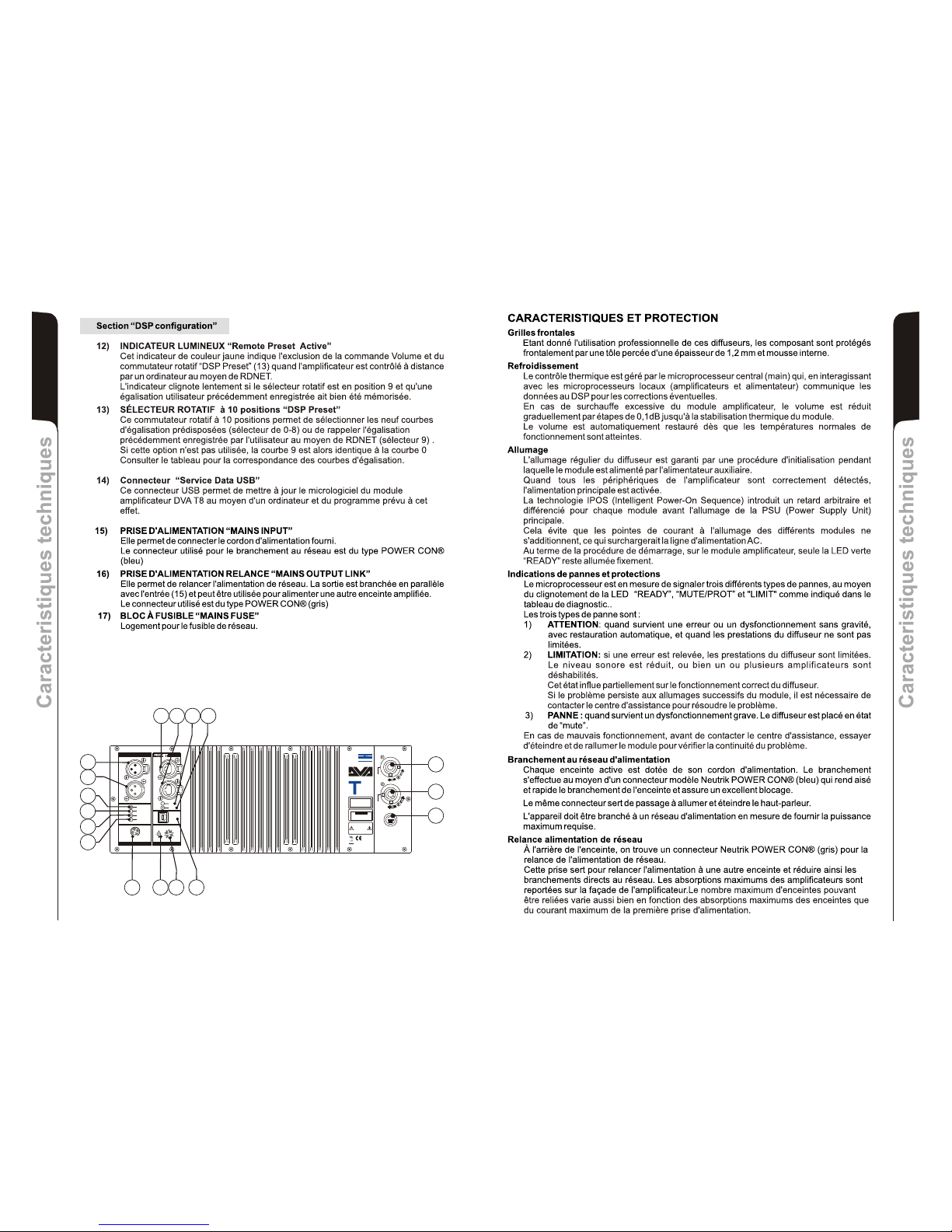
Français
Caracteristiques techniquesCaracteristiques techniques
37
Caracteristiques techniquesCaracteristiques techniques
Français
38
7
15
16
17
Made in Italy
Input
Link
Audio
Input Sens
READY
MUTE/PROT
SIGNAL
LIMITER
0dB
+10dB
+4dB
1 = GND
2 = HOT
3 = COLD
1
0
2
3
4
5
6
7
8
9
Active
Data
Link
Link
Active
Data
Input
Input Control
Balanced Audio
Status
Service
Data
User
Remote
Preset
DSP Configuration
SERIAL N.
“CAUTION”
RISK OF ELECTRICAL SHOCK
DO NOT OPEN
“AVIS”
RISQUE DE CHOCH ELECTRIQUE
NE PAS OUVRIR
dd
BB
TECHNOLOGIESTECHNOLOGIES
(REPLACE FUSE WITH SAME RATINGS)
MAINS
FUSE
220-240V~
(18Amax)
3680Wmax
100-120V~
(16Amax)
1320Wmax
100-120V~
4Amax
MAINS
LINK
MAINS
INPUT
FULL RANGE
ACTIVE P.F.C.
100-240V~ 50-60Hz
Digital Vertical Array
8
220-240V~
2Amax
220-240V~
(T3,15A L 250V~)
100-120V~
(T6,3A L 250V~)
PUSH
PUSH
PUSH
1
2
6
5
4
3
11
10
98
14
13
12
L177007324
REV SW 2.32
Page 21
Français
Caracteristiques techniquesCaracteristiques techniques
39
Caracteristiques techniquesCaracteristiques techniques
Français
40
DONNES TECHINIQUES
Système
Typologie amplificateur
Puissance
Puissance m
Pression sonore
Composantes
Entrée sensibilité
Impedance entrée
Symétrique
Asymétrique
Alimentation
Dimensions (WxHxD)
Poids
Poignée un de chaque côté
Active 3-Amps
Digital - Class D
DIGIPRO G2 technologie
RMS 700W
Haute (HF) RMS 175W
Mide (MF) RMS 175W
Faible (LF) RMS 300W
usicale 1400W
Réponse en fréquence (-6dB) 66-18.000Hz
Réponse en fréquence (-10dB) 61-19.900Hz
Crossover MF-HF (Mide-Haute) 1900Hz
24dB/Oct
Crossover LF-MF (Faible-Mide) 400Hz
24dB/Oct
(SPL) 132dB max
1 woofer 8" - VC 2.5" - Neodymium
1 midrange 6,5" - VC 2" - Neodymium
2 compression driver 1" - VC 1.4” Neodymium
0dBu
20Kohm
10Kohm
Full-range with PFC and SMPS
100-240V~ 50-60Hz
Courant d'appel 3,3A
580x386x327mm
(23,2x9,6x13,08 inch.)
14,2Kg
(31,3 lbs)
PROCESSEUR DSP
DSP Analog Device 56 bits
Transformation audio 24 bit / 96kHz S/N=114dB
Contrôle du volume Digital
galisation 9 preset EQU
PIECES MECANIQUES
Matériel Box Polipropilene (PP)
Box renforcement interne Acier
Matériel d'appui Flying Acier
Angle support 0° - 1,5° - 3° - 4,5° - 6° - 8° - 10° - 12,5° - 15°
Forme enceinte Trapézoïdale - angle 15°
Grilles frontales 1.2mm et mousse interne
®
È
CLASSIFICATION EMI
En accord aux les normes EN 55103, l'équipement est conçu et convenable pour une
utilisation en environnement électromagnétique E3 ou inferieur (E2,E1).
A D U C O MOD LEÉT T U MOD LE ON TI NS U
É É É ule f nc o e no leme .teint teint teint Le mod o ti nn rma nt
v um PUT e om u at r r i DS ese ont a i sLe ol e (IN SENS) et l c m t eu otat f ( P Pr t)
s ct f
C t men y iq u e a p i s c t ôlé à dis c a e R N Tligno e t c cl ue Le mod l m lif cateur e t on r tan e p r l D E .
v um PUT e om at ur r i DS ese ontLe ol e (IN SENS) et l c mut e otat f ( P Pr t)
s
és ar by aévit p -p ss
É lis S C ot men q É t É t u e f nc e no m lemega ation «U ER EQ» lign e t cycli ue tein tein Le mod l o tionn r a nt.
( mmuta eu ota if gal i egi t ée ar RD lco t r r t L'é isat on enr s r p NET est uti isée.
D P es t os ioS Pr e » en p it n 9)
LE LE LED D D F
« » «LIN « TI »K» AC VE
D ET a ifR N p s act
ET c e I ée I eR
DN on ctes llumin lluminé
m e P se A i eRe ot re t ct v
ÉTAT LED LED LED LED FONCTIONS MODULE
DU MODULE «READY» «MUTE/PROT» «SIGNAL» «LIMIT»
Mise sous tension Éteint Sous tension x 5 s. Éteint Éteint Audio en MUTE
Initialisation du module amplificateur
Utilisation normale Illuminée Éteint Fonctionnement normal Fonctionnement normal Audio ACTIVE
Initialisation du module terminée et correcte
Fautepartielle Illuminée Clignotement cyclique Fonctionnement normal Fonctionnement normal Audio ACTIVE
(3 ou plusieurs Le module a relevé une anomalie partielle et reste
Clignotements Rapides) actif mais avec des fonctionnalités limitées
Faute franc Éteint Illuminée Éteint Clignotement cyclique Audio en MUTE
Le module a relevé une anomalie grave et se met
en protection
Gestion amplificateur de température
Première de seuil Illuminée Clignotement cyclique Fonctionnement normal Fonctionnement normal Audio ACTIVE
thermique (1clignotements lents) Le module amplificateur commence une diminution
progressive du volume dans les étapes 0.1dBm pour
compenser 'augmentation de température jusqu'à une
réduction maximale de 3 dBm.
Deuxième de seuil Sous tension Clignotement cyclique Fonctionnement normal Fonctionnement normal Audio ACTIVE
thermique (2 clignotements rapides) Le module amplificateur réduit le volume de 3dBm
supplémentaires toujours de 0.1dBm progressif à
passer à une réduction maximale des autres 3dBm,
pour une réduction totale de 6dBm par rapport au
volume initial.
NB Les températures indiquées sur le plug-in logiciel RDnet se réfèrent à la température interne des semi-conducteurs de puissance.
Ces températures ne sont pas affichées les températures de l'utilisateur des pièces accessibles
TABLEAU DE DIAGNOSTIC
Page 22
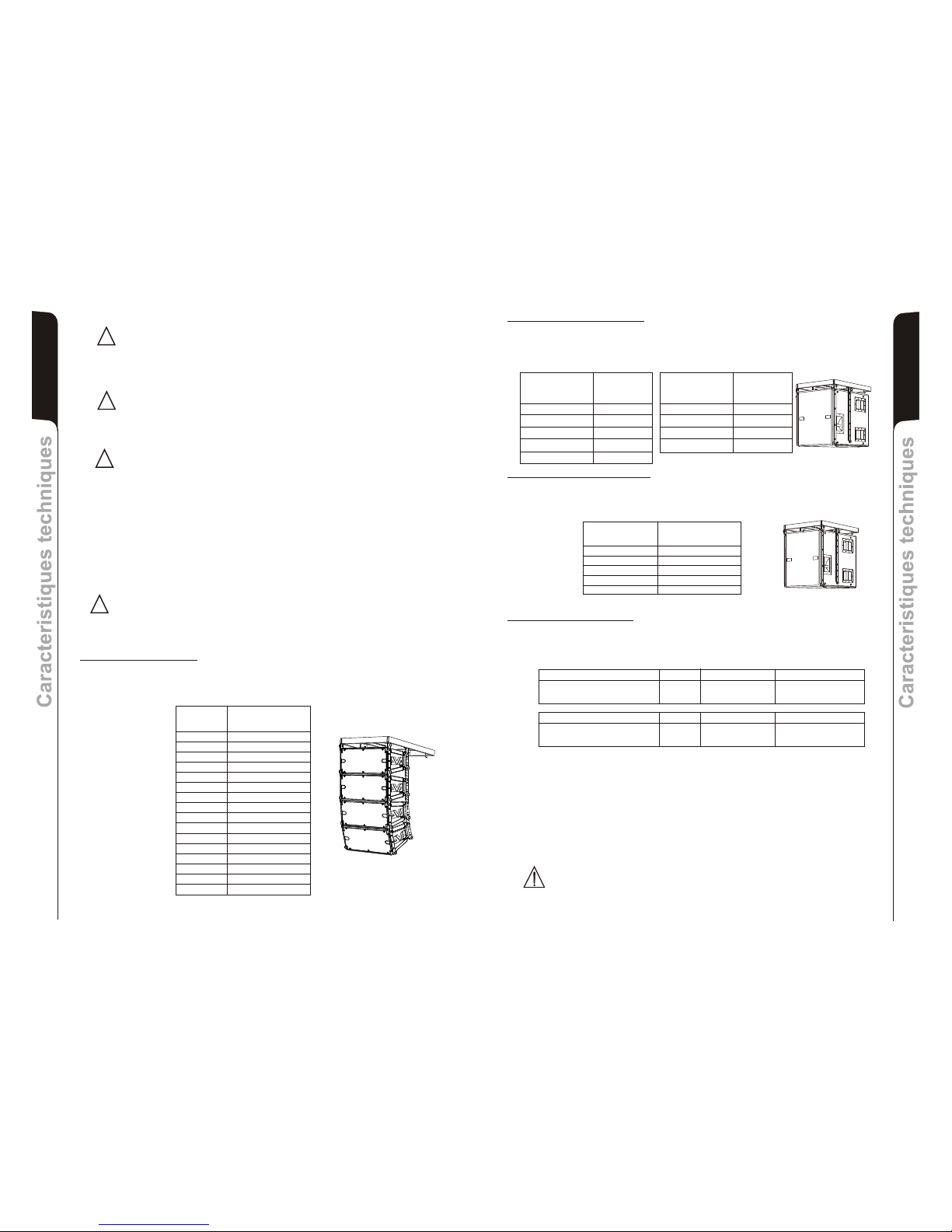
42
Caracteristiques techniquesCaracteristiques techniques
Français
41
Français
Caracteristiques techniquesCaracteristiques techniques
INSTALLATION
DRK 20
Le dispositif flybar DRK 20M et les systèmes d'accrochage prévus pour les diffuseurs
DVA T4, DVA T8, DVA T12, DVA S09dp, DVA S10dp, DVA S1518N et DVA S2585N ont été
conçus et vérifiés au moyen d'essais techniques de rupture conformément aux
documents, Décret Ministériel Italien D.M. du 14.01.2008 “Nouvelles normes techniques
pour les constructions” et “Eurocode 1” et “Eurocode 3” en ce qui concerne les structures
en acier.
Le système a été vérifié techniquement et certifié conforme aux valeurs de portée
maximum déclarées par une Attestation de Conformité délivrée par CERMET, n.reg. PA
68913 V 00001 2011.
Le DRK 20M ne doit être utilisé que par un personnel qualifié !
Les calculs structuraux montrent que le poids maximum applicable au flybar DRK20 est
fonction du point de fixation du crochet de soulèvement.
!
DRK 10
Le système DVA a obtenu la certification TÜV pour la suspension des diffuseurs DVA T4,
DVA T8, DVA S09dp, DVA S10dp, DVA S1518N et DVA S2585N grâce à l'étrier flybar
DRK10.
Le rapport certifie que le poids maximum applicable au flybar DRK10 est de 250kg.
DANGER ! Respecter scrupuleusement la charge admise.
L'absence de respect de toutes les instructions peut provoquer un danger de chute de la
structure et de son contenu, ce qui pourrait occasionner des dommages à des personnes,
des choses et des animaux.
Configurations avec DVA S10dp
Le flybar DRK10 est certifié pour un maximum de 5 diffuseurs DVA S10dp avec
Neodymium woofer ou pour un maximum de 4 diffuseurs DVA S10dp avec Ceramic
woofer. Consulter le tableau 2 afin de déterminer le poids compressif supporté par le
flybar avec diffuseurs DVA S10dp dans différentes configurations.
Configurations avec DVA S1518N
Le flybar DRK10 est certifié pour un maximum de 5 diffuseurs DVA S1518N. Consulter le
tableau 2 afin de déterminer le poids compressif supporté par le flybar avec diffuseurs
DVA S1518N dans différentes configurations.
Quantity Weight
[kg] [lbs.]
1 46 102
2 92 203
3 138 304
Table 3 4 184 405
5 230 506
(Neodymium woofer)
Configurations avec DVAT4
Le flybar DRK10 est certifié pour un maximum de 16 diffuseurs T4
Consulter le tableau 1 afin de déterminer le poids compressif supporté par le flybar avec
diffuseurs DVA T4 dans différentes configurations.
Quantité Poids
DVA T4 [kg] [lbs.]
1 15 33
2 30 66
3 45 99
4 60 132
5 75 165
6 90 198
7 105 231
8 120 264
9 135 297
10 150 330
11 165 363
12 180 396
13 195 429
14 210 462
15 225 495
16 240 528
Quantité Poids
DVA S10dp [kg] [lbs]
(Neodymium woofer)
1 48 106
2 96 212
3 144 317
4 192 423
5 240 528
Quantité Poids
DVA S10dp [kg] [lbs]
(Ceramic woofer)
1 54 119
2 108 238
3 162 357
4 216 476
Configurations avec mélange
La modularité du système DVA permet des configurations suspendues mixtes entre les
diffuseurs. C'est pour ce motif qu'il est nécessaire de calculer la charge totale dans les
différentes combinaisons.
Exemple:
Tableau 2
Tableau 1
ATTENTION
Installer le diffuseur de façon stable et sûre afin d'éviter toute condition de danger
pour l'intégrité des personnes et des structures.
Avant de suspendre le diffuseur, contrôler tous les composants à utiliser, qui ne doivent
présenter aucun dommage, aucune déformation ou partie manquante ou abimée qui
seraient susceptibles de réduire la sécurité de l'installation.
ATTENTION
L'utilisation du diffuseur sur support avec pied doit être effectué par un personnel
professionnel qualifié qui doit veiller à positionner un pied de support en direction du
coté où sort le son (côté antérieur du diffuseur) de manière à optimiser la stabilité par
rapport au barycentre du diffuseur (réf. Page 58).
ATTENTION
Pour l'utilisation du diffuseur avec support en colonne pour caisson de basse -pole
mount- (réf. Page 59), afin d'éviter tout risque de basculement et dommages à
personnes, animaux ou choses et avant de procéder à l'installation du système,
vérifier sur le site dBTechnologies les configurations admises, les indications et
prescriptions. Dans tous les cas, s'assurer que le caisson de basse de support du
diffuseur soit positionné sur une surface horizontale dépourvue d'inclinaisons.
!
!
!
Quantité Poids par quantité Poids configuration
DVA T8 8 120Kg
DVA S10dp (Neodymium woofer) 2 96Kg
Quantité Poids par quantité Poids configuration
DVA T8 12 180Kg
DVA S1518N (Neodymium woofer) 1 46Kg
216Kg
226Kg
Page 23
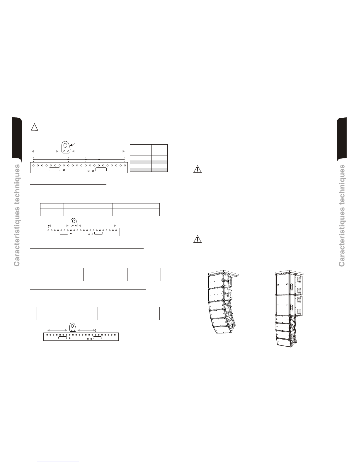
44
Caracteristiques techniquesCaracteristiques techniques
Français
43
Français
Caracteristiques techniquesCaracteristiques techniques
Modifications structurelles du support flybar
Il est interdit apporter des modifications, quelles qu'elles soient, à la structure du flybar et
aux étriers correspondants fournis comme accessoires des haut-parleurs mêmes.
Altérer et/ou modifier la structure ou les accessoires fournis peut provoquer un danger
d'affaissement ou de rupture.
Accessoires originaux dB Technologies
Il est interdit utiliser des pièces et des accessoires différents de ceux qui sont fournis.
N'utiliser que les pièces originales fournies par dBTechnologies.
Toute installation et utilisation des pièces fournies doit être exécutée conformément aux
instructions de montage qui accompagnent le dispositif.
Conserver et mettre aux archives en un lieu sûr tous les documents du système DVA !
Attention
La dB Technologies ne peut être tenue pour responsable de dommages
occasionnés à des personnes, des choses et des animaux au cas où les
prescriptions de sécurité et les calculs des poids maximums ne seraient pas
respectés !
Remarques
Pendant les installations, il faut s'assurer que. dans la structure portante du système, sont
également inclus, pour le calcul des poids totaux, le poids du flybar, des chaînes des
élévateurs, des moteurs, des câbles et d'autres poids additionnels.
Lancement et fonctionnement
§ 39, VBG 9a sur l'assurance obligatoire de la part des employeurs allemands pour la
prévention des accidents exige que l'équipement du charge-portant doive être inspecté
par un personnel qualifié et que les défauts éventuels doivent être éliminés avant la
remise à l'utilisateur final.
§ 41 VBG 9a exige que l'équipement du charge-portant doive faire l'objet d'un entretien
non ordinaire à la suite de dommages, de réparations et d'autres accidents qui peuvent
avoir un effet sur la capacité du charge-portant.
Attention
Les normes sur la sécurité peuvent être différentes dans le pays de destination.
L'utilisateur est tenu de vérifier les réglementations et les lois qui sont en vigueur en
matière de sécurité dans le pays dans lequel il utilise le produit !!
DANGER ! Respecter scrupuleusement la charge admise en fonction du point
de fixation du crochet de soulèvement.
L'absence de respect de toutes les instructions peut provoquer un danger de
chute de la structure et de son contenu, ce qui pourrait occasionner des
dommages à des personnes, des choses et des animaux.
!
5
4
6
2
1
3
11
10
12
8
7
9
17
16
18
14
13
15
22
20
19
21
1200Kg
(12KN)
1000Kg
(10KN)
1300Kg
(13KN)
750Kg
(7.5KN)
1 - 9 1200kg
9 - 13 1300kg
13 - 16 1000kg
16 - 22 750kg
ROCHET DE SOULÈVEMENT
Point de fixation
du crochet de
soulèvement
Capacité de
charge
admise
Configurations avec mélange DVA T8 et DVA T12
La modularité du système DVA permet des configurations suspendues mixtes entre les
diffuseurs DVA T8 et DVA T12. C'est pour ce motif qu'il est nécessaire de calculer la
charge totale dans les différentes combinaisons.
Exemple:
Quantité Poids par quantité Poids configuration
DVA T12 10 300Kg
DVA T8 6 90Kg
390Kg
Configurations avec mélange DVA T8 et DVA S10dp (Neodimium woofer)
(Neodimium woofer)
La modularité du système DVA permet des configurations suspendues mixtes entre les
diffuseurs DVA T8 et DVA S10dp . C'est pour ce motif qu'il est
nécessaire de calculer la charge totale dans les différentes combinaisons.
Exemple:
5
4
6
2
1
3
11
10
12
8
7
9
17
16
18
14
13
15
222019
21
5
4
6
2
1
3
11
10
12
8
7
9
17
16
18
14
13
15
22
20
19
21
Configurations avec mélange DVA T8 et DVA S1518N (Neodimium woofer)
(Neodimium woofer)
La modularité du système DVA permet des configurations suspendues mixtes entre les
diffuseurs DVA T8 et DVA S1518N . C'est pour ce motif qu'il est
nécessaire de calculer la charge totale dans les différentes combinaisons.
Exemple:
Quantité Poids par quantité Poids configuration
DVA T8 14 210Kg
DVA S10dp (Neodymium woofer) 4 192Kg
Quantité Poids par quantité Poids configuration
DVA T8 20 300Kg
DVA S1518N (Neodymium woofer) 4 184Kg
402Kg
484Kg
DVA T8
DVA T12
DVA T8
DVA S1518N
Page 24
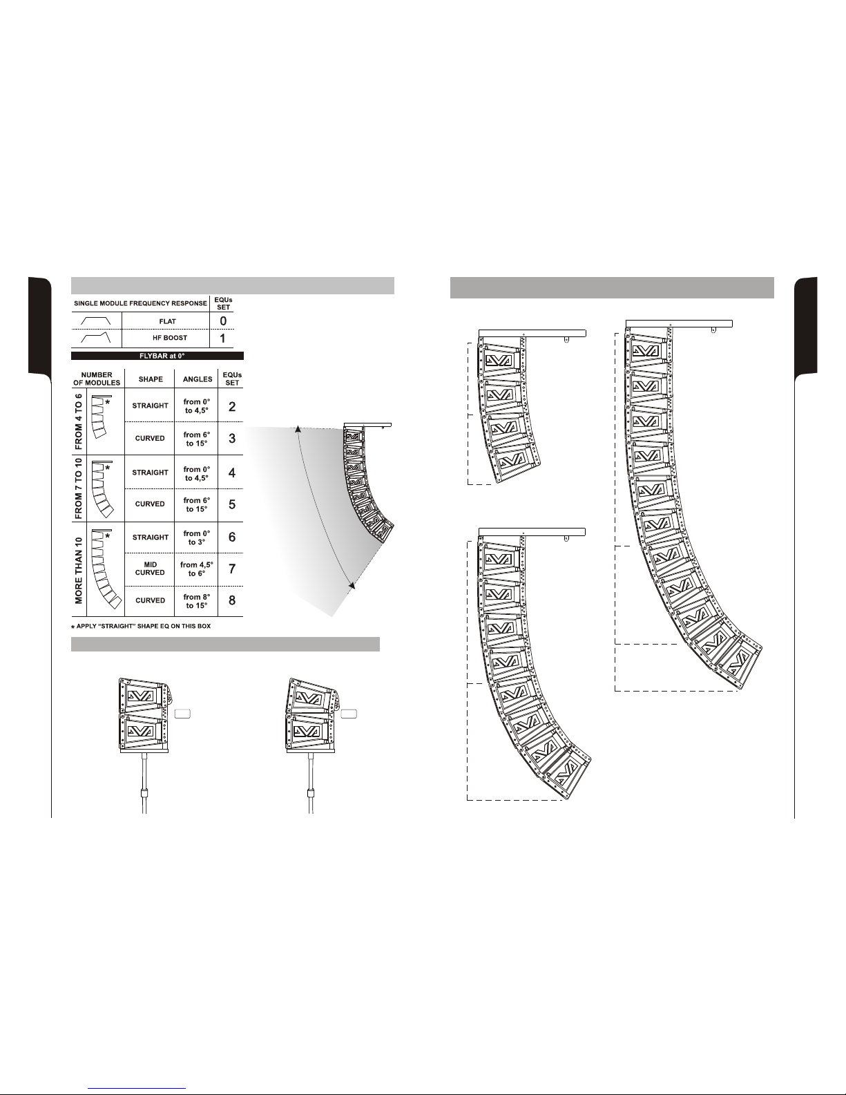
SET-UP EXAMPLES
E
G
A
R
E
V
O
C
DVA T8 QUICK CONFIGURATIONS
CONFIGURATION FRONT FIELD
N 2
:
°OF BOX:
CONFIGURATION FRONT FIELD
N 2
:
°OF BOX:
set-up 0
set-up 1
set-up 0
set-up 1
0°
6°
SET-UP EXAMPLES
set-up 2
set-up 2
set-up 3
set-up 3
STRAIGHT
from 0° to 4,5°
from 6° to 15°
CURVED
CONFIGURATION LINE ARRAY
N 4
:
°OF BOX:
set-up 8
STRAIGHT
from 0° to 3°
from 8° to 15°
set-up 8
from 4,5° to 6°
set-up 7
set-up 7
set-up 7
set-up 6
set-up 6
set-up 6
set-up 6
set-up 6
set-up 6
CONFIGURATION LINE ARRAY
N 11
:
°OF BOX:
CURVED
MID CURVED
set-up 4
set-up 4
set-up 4
set-up 4
set-up 5
set-up 5
set-up 5
set-up 5
STRAIGHT
from 0° to 4,5°
from 6° to 15°
CURVED
CONFIGURATION LINE ARRAY
N 8
:
°OF BOX:
45
46
Page 25
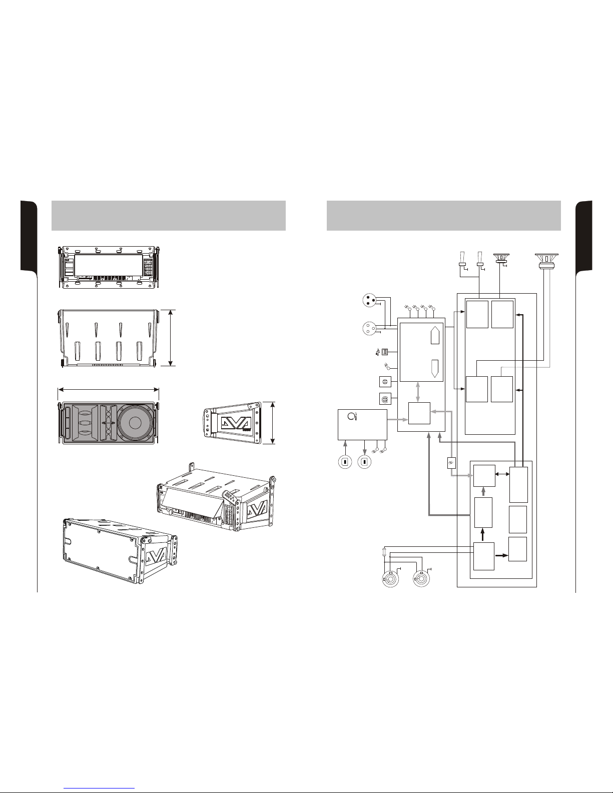
48
47
SCHEMA A BLOCCHI
BLOCK DIAGRAM
BLOCKSCHALTBILD
SCHEMAS FONCTIONNELS
DIMENSIONI
DIMENSIONS
ABMESSUNGEN
DIMENSIONS
DAC
BALANCED
LINK/OUTPUT
RDNET
L
N
FULL RANGE
MAINS INPUT
MAINS LINK
WOOFER 8”
MIDRANGE 6,5”
COMPRESSION
DRIVER 1”
COMPRESSION
DRIVER 1”
Switching Mode
Power Supply
PFC
Power Factor
Correction
SMPS
MAINS
FUSE
DSP
28/56 bit Audio processor core
Power Supply Unit
PSU main
ADC
Analogic Digital
Converter
Digital Analogic
Converter
EMI filter
ElectroMagnetic
Interference
filter
Power Supply Unit
PSU auxiliary
CPU
(SLAVE)
CPU
(MASTER)
Filtered AC
Ready
Limiter
Signal
Mute/Prot
Data
Input
Data
Link
Service
Data
USB
Remote
Preset
Active
Link
Active
0dB
+4dB
Input
Sens
0
1
2
3
4
5
6
7
8
9
DSP
Preset
BALANCED
INPUT
POWER SUPPLY
Balanced
Audio
High voltage
I2C
UART
(serial communication)
Digital Signal Processor
AMPLIFIER
PREAMPLIFIER
MODULE
Auxiliary voltage
Low voltage
Balanced
Audio
RS485
Filtered AC
Filtered AC
Class D
DIGIPRO G2
Class D
DIGIPRO G2
Class D
DIGIPRO G2
Class D
DIGIPRO G2
RS485
96KHz Sample Rate
96KHz Sample Rate
96KHz Sample Rate
Main Board
Digital isolator
580
240
327
Made in Italy
“CAUTION”
RISK OF ELECTRICAL SHOCK
DO NOT OPEN
“AVIS”
RISQUE DE CHOCH ELECTRIQUE
NE PAS OUVRIR
ae n ItalyM d i
udiAo
I Sensnput
0dB
+10dB
4dB
+
1
0
2
3
4
5
6
7
8
9
tAcive
np o roI ut Cnt l
serU
Remote
sPreet
S C nfigur iD P o aton
“AVIS”
RIQEDECHCH LE RQUSU O ECT I E
NE S OUVRIPA R
Page 26
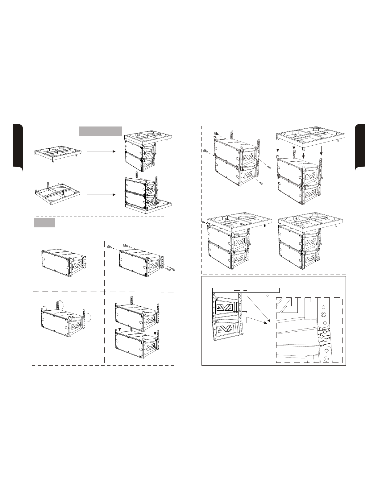
49
50
INCLINAZIONE INCLINATION
NEIGUNG INCLINAISON
EESRISEESRIS
Phase 6
Phase 5
Phase 7
Phase 8
DRK 10 accessorio
Accessory DRK 10
Appeso
Hanging on
In appoggio
Groundstack
Phase 1
Phase 2
Phase 4
Phase 3
INSTALLAZIONE INSTALLATION
INSTALLATIONEN INSTALLATIONS
Appeso
Hanging on
5
°
4,
6
°
8°
10
°
2
1
,
5 °
1°
5
Page 27
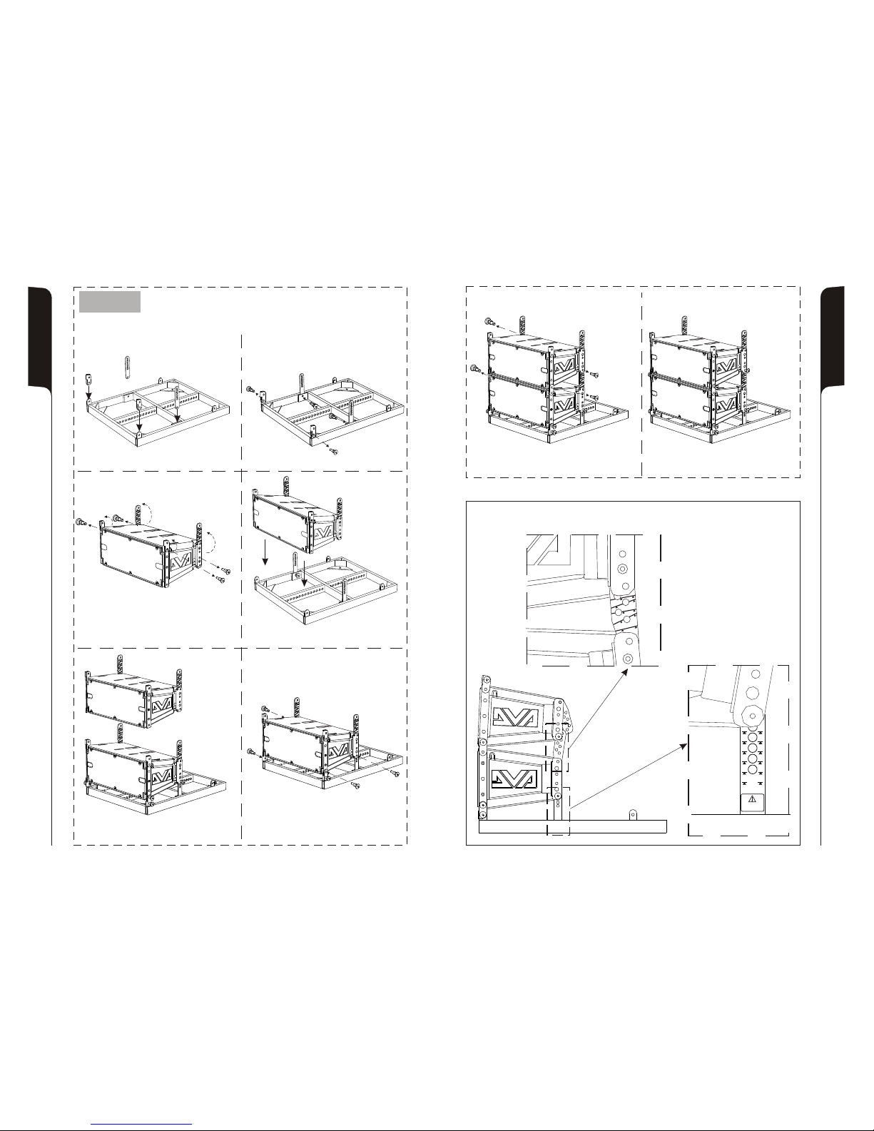
51
52
Phase 1 Phase 2
Phase 5
Phase 7
Phase 8
Phase 3
Phase 4
Phase 6
0°0° 0°0°
5°5° 5°5°
2,5°2,5°
GROUND STACKED
USE ONLY
GROUND STACKED
USE ONLY
2,5°2,5°
-2,5°-2,5° -2,5°-2,5°
-7,5°-7,5° -7,5°-7,5°
-5°-5° -5°-5°
RSSEIERSSEIE
In appoggio
Groundstack
INSTALLAZIONE INSTALLATION
INSTALLATIONEN INSTALLATIONS
INCLINAZIONE INCLINATION
NEIGUNG INCLINAISON
,5
4
°
°6
8°
0°1
°
,5
12
5°1
Page 28
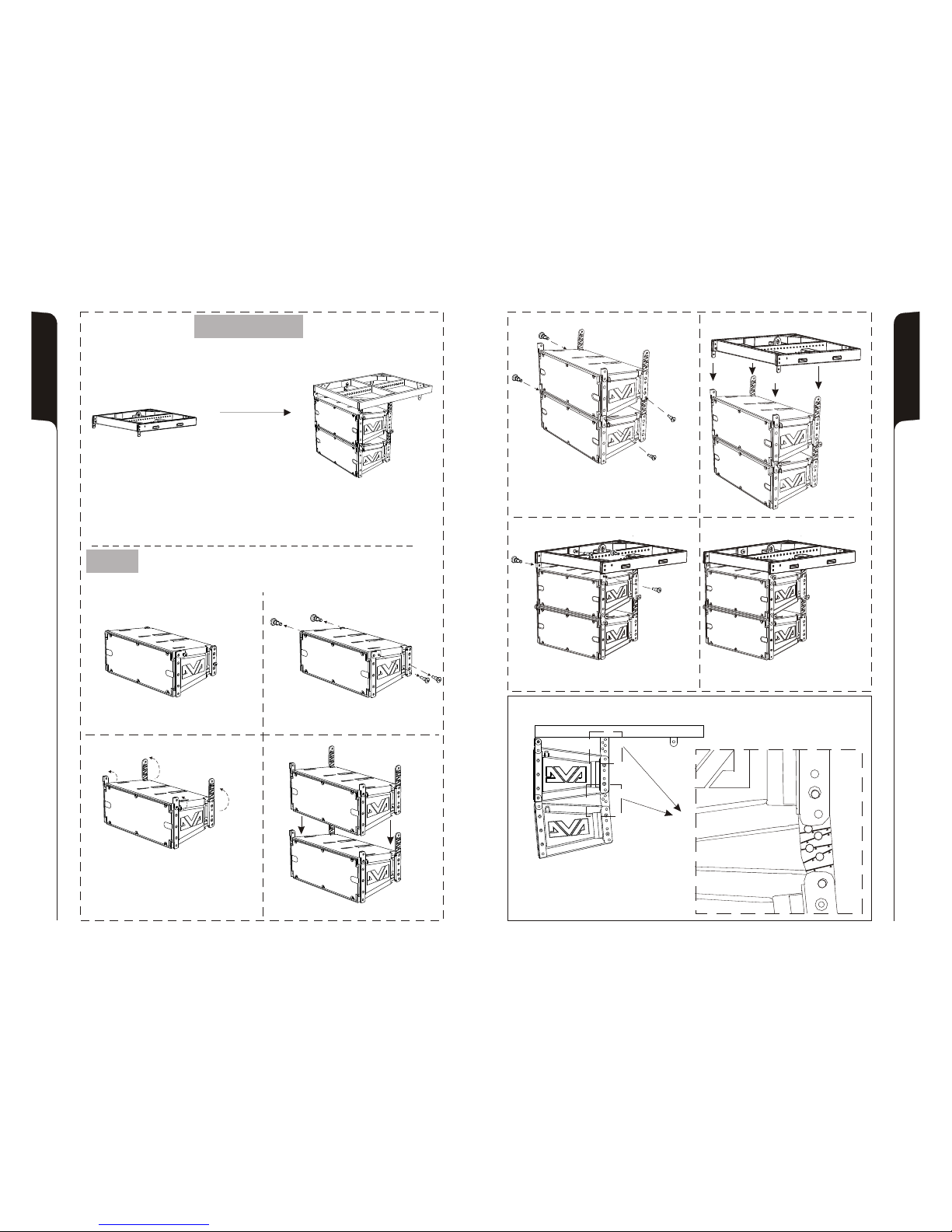
53
54
DRK 20 accessorio
Accessory DRK 20
Appeso
Hanging on
Appeso
Hanging on
Phase 1 Phase 2
Phase 4Phase 3
INSTALLAZIONE INSTALLATION
INSTALLATIONEN INSTALLATIONS
INCLINAZIONE INCLINATION
NEIGUNG INCLINAISON
EESRISEESRIS
Phase 6
Phase 5
Phase 7
Phase 8
5
°
4,
6
°
8°
10
°
2
1
,
5 °
1°
5
Page 29
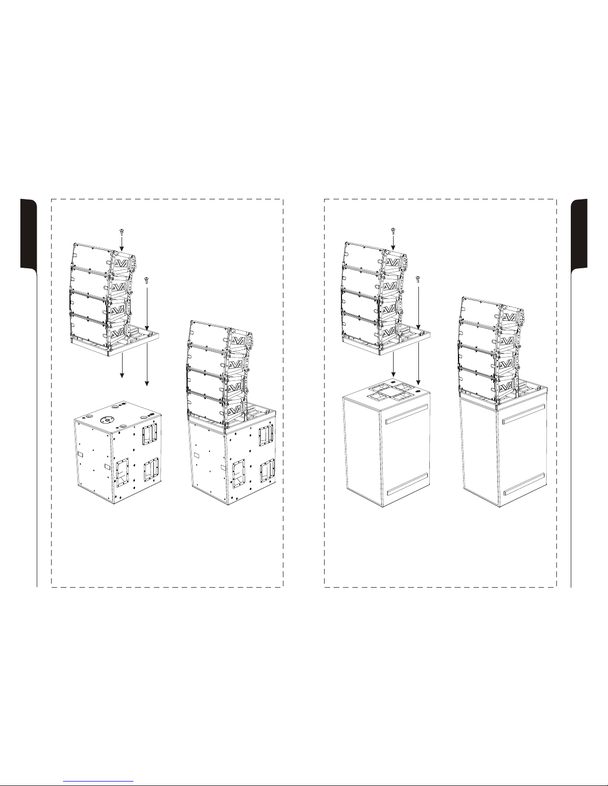
DVA T8 + DVA S1518N
Utilizzo in appoggio verticale (DVA T8 montaggio “Ground stacking”)
Supported use (DVA T8 “Ground stacking” assembling)
DVA T8 + DVA S30N
Utilizzo in appoggio verticale (DVA T8 montaggio “Ground stacking”)
Supported use (DVA T8 “Ground stacking” assembling)
55
56
Page 30
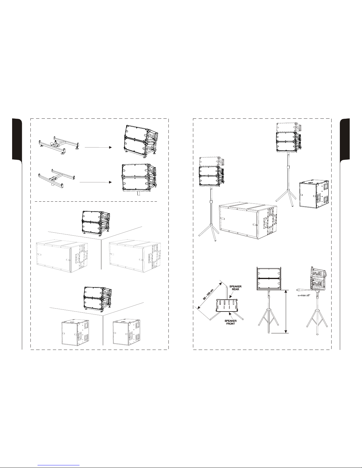
Per supporto asta
Stand adaptor
Opzione DSA 4
DSA 4 Option
In appoggio
Floor stack
Per supporto asta
Stand adaptor
In appoggio
Floor stack
57
58
130 cm130 cm
Page 31
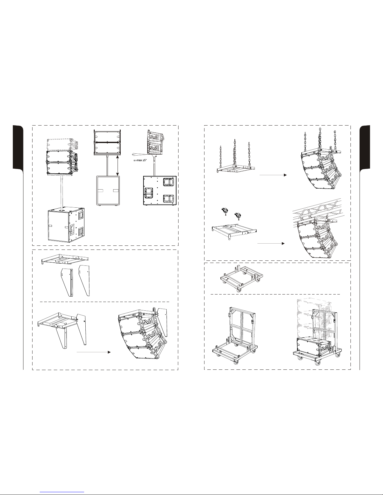
Staffa a muro - opzione DWB 3
Wall bracket - DWB 3 option
Fissaggio a muro con staffe
Wall brackets fixing
Fissaggio a muro con staffa e catene
Wall bracket and chains fixing
Gli accessori per il fissaggio della staffa
non sono forniti in dotazione
The fixing accessory for wall bracket are
not suppling with the kit
Fissaggio su strutture a traliccio
Fixing on truss structures
59
60
Solo con / Only with
DVA S10dp or DVA S1518N
Per supporto asta
Stand adaptor
87 cm
Carello - opzione DT 6
Trolley - DT 6 option
Carello
Trolley
Flybar
Page 32
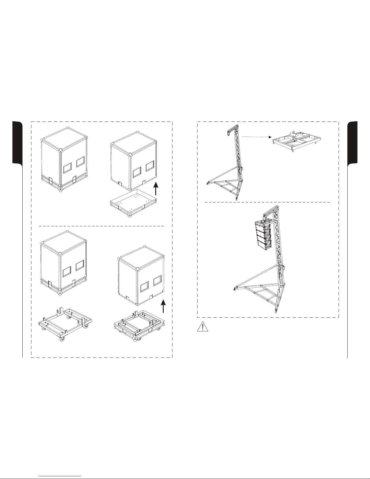
Flightcase per 4 DVA T8 - opzione DF 4
Flightcase for 4 DVA T8 - DF 4 option
Opzione DTF 4
DTF 4 Option
DTF 4 = DT 6 + DF 4
Quando viene utilizzato un carrello, usare cautela durante lo spostamento
dell’apparecchio per evitare infortuni a causa di capovolgimenti.
When a cart is used, use caution when moving the cart-apparatus combination to
avoid injury from tip-over.
Beim Verfahren des Geräts auf einem Wagen darauf achten, dass es nicht zu
Unfällen kommt, weil das Gerät umkippt.
Quand on utilise un chariot, déplacer l'appareil avec précaution afin d'éviter des
accidents à cause de renversements.
61
62
Sollevatore per diffusori - opzione DRL 45
Lift for speakers - DRL 45 option
Nota:
Utilizzare il sollevatore solo con l’accessorio
DRK 10 (flybar)
Note:
To use the lift of speaker only with DRK 10
accessory (flybar)
 Loading...