

AEB QSB, QSC, QSL9, QSM11, QSX15 Diagram
...
Application
Engineering
Bulletin
Subject This AEB is for the following applications:
Installation Recommendations
Automotive Industrial Power Generation
Date April 2001 (Rev Dec 2001) Page 1 of 38 AEB Number 15.44
Engine Models included: QSB,QSC,QSL9,QSM11,QSX15,QSK19,QST30,QSK45,QSK60
Fuel Systems included:
Changes in blue
Introduction
The Quantum Installation Recommendations Technical Package was written to assist OEMs in integrating
Quantum engines into their equipment. This technical package includes the wiring diagram, pinouts, and other
pertinent information needed to install a Quantum engine
Refer to the following other Industrial AEB’s:
AEB 15.40 – Electronic Features
AEB 15.42 – OEM Components and Interfaces
AEB 15.43 – Datalinks and Diagnostics
Authors: Scott Decker, Michael L. Hill, Brian Landes, Jeffrey Martin, Stewart Sullivan, Tiffany Walker

AEB15.44
Page 2 of 38
Table of Contents
Introduction ......................................................................................................................................... 1
Table of Contents................................................................................................................................. 2
Section I – Grid Heaters .................................................................................................................... 3-4
Section II – Power and Ground Requirements..................................................................................4-5
System Grounding Requirements ..................................................................................................... 4
High-Current Accessory Grounds ......................................................................................................4
Cylinder Block as Ground................................................................................................................. 4
Starter Ground .................................................................................................................................4
Frame Returns .................................................................................................................................4
Switches and Sensor Grounding Requirements................................................................................. 5
Solenoid Grounding Requirements.................................................................................................... 5
Section III – Keyswitch Requirements.................................................................................................. 6
Keyswitch Connection Requirements................................................................................................ 6
Sourcing.......................................................................................................................................... 6
Fusing............................................................................................................................................. 6
Inductive Load Sharing ..................................................................................................................... 6
Fault Lamp/Keyswitch Wiring Configuration....................................................................................... 6
Optional 2-Lamp Strategy Wiring...................................................................................................... 6
Section IV – Welding Requirements..................................................................................................... 7
Section V – OEM Harness and Harness Routing ............................................................................... 7-8
Wire Section ....................................................................................................................................7
Contacts and Connectors ................................................................................................................. 7
Protective Covering ..........................................................................................................................8
Harness Routing and Support........................................................................................................... 8
Section VI – Datalink Requirements for QSM11 and QSX15 .................................................................9
Section VII – Wiring Diagrams/Pin Mapping ................................................................................. 10-18
QSK45/60 Cense Wiring Diagram...................................................................................................10
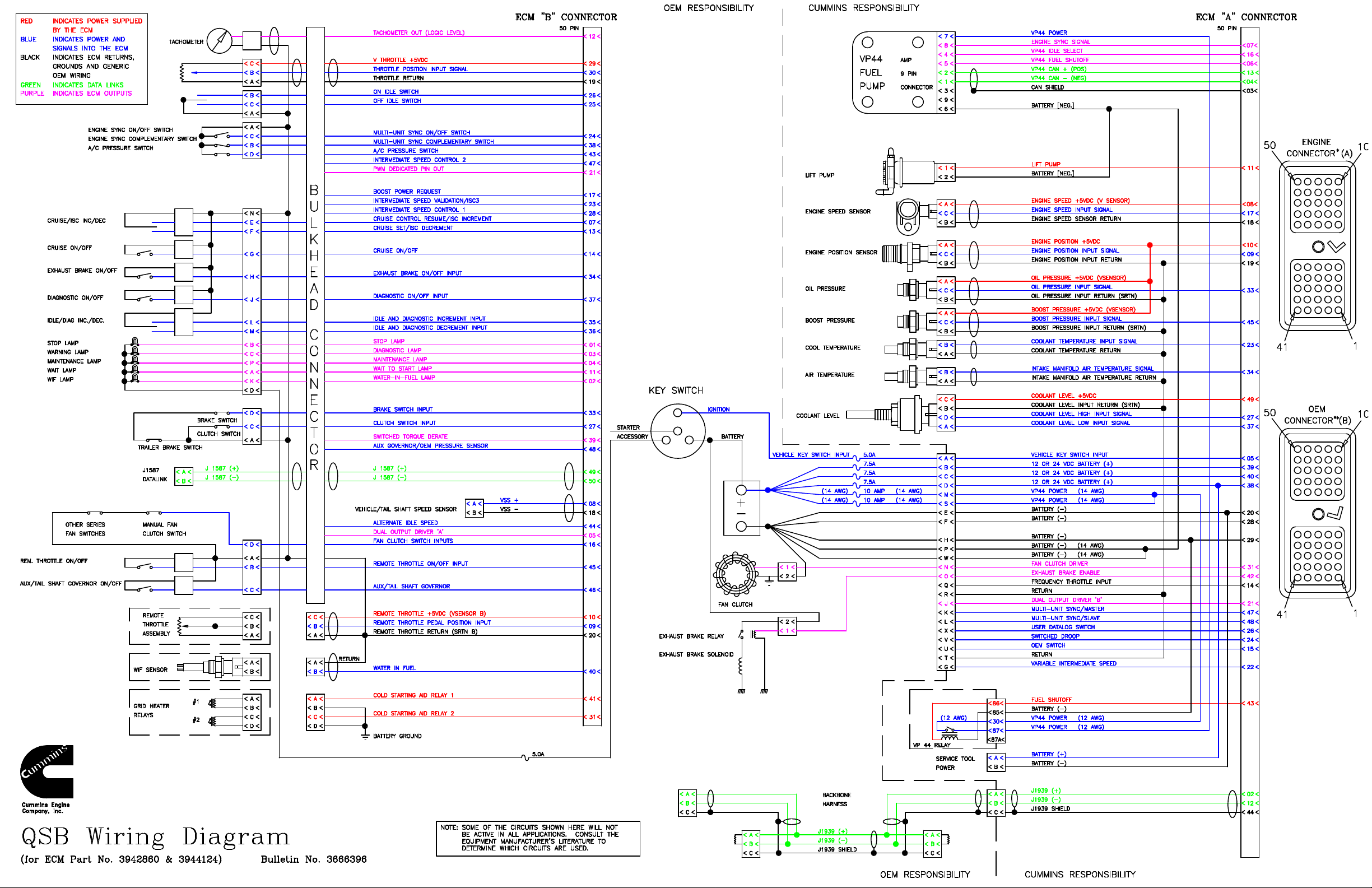
QSB Wiring Diagram ......................................................................................................................12
QSC Wiring Diagram......................................................................................................................14
QSM11 Wiring Diagr am..................................................................................................................16
QSX15 Wiring Diagram..................................................................................................................18
QSK19/45/60 Wiring Diagram .........................................................................................................20
QST30 Wiring Diagram ..................................................................................................................22
QSB Pin Mapping ..........................................................................................................................24
QSC/QSL9 Pin Mapping............................................................................................................ 25-26
QSM11/QSX15 Pin Mapping..................................................................................................... 26-28
QSK19 Pin Mapping.................................................................................................................. 29-30
QST30 Pin Mapping .................................................................................................................. 30-31
Section VIII – Pinout Specifications.............................................................................................. 32-43
5V Sensor Voltage Source Pinout Specifications ..............................................................................32
5V Switched Pullup Input Pinout Specifications................................................................................33
10V Switched Pullup Input Pinout Specifications..............................................................................34
ECM Supply and Return Pinout Specifications.................................................................................35
Ratiometric Analog Input Pinout Specifications ................................................................................36
Resistive Analog Input Pinout Specifications ....................................................................................37
Switched Pulldown Input Pinout Specifications .................................................................................38
Switched Sink Driver Output Pinout Specifications ...........................................................................39
Switched Source Driver Output Pinout Specifications .......................................................................40
Tachometer Source Driver Output Pinout Specifi cations...................................................................41
Variable Reluctance Input Pinout Specifications (Differential Input)...................................................42
Variable Reluctance Input Pinout Specifications (Single-Ended Input)...............................................43

AEB15.44
Page 3 of 38
Section I - Grid Heaters
QSB, QSC, QSL9
The intake air heater system is used to aid in starting during cold temperatures and to reduce white smoke after
such a start. The system consists of two heater elements that are controlled by the ECM via two high current
relays. Grid heaters are required for QSB/C/L9 engines.
Note: The installer is responsible for procuring and mounting the grid heater power relays in a location
free of road splash and also for routing battery connections through the relay contacts to the (2) grid
heaters which are shipped with the engines. The intake air heater relays must not be mounted on engine.
Since power routed to the grid heaters is through one wire then the gauge of the wire should be 2 AWG minimally
since each of the grid heating elements require 105 amps during the heating cycle. The gauge of the wire from
the grid heater, relays to the grid heater elements, also need to be 6 AWG minimally to carry the required current.
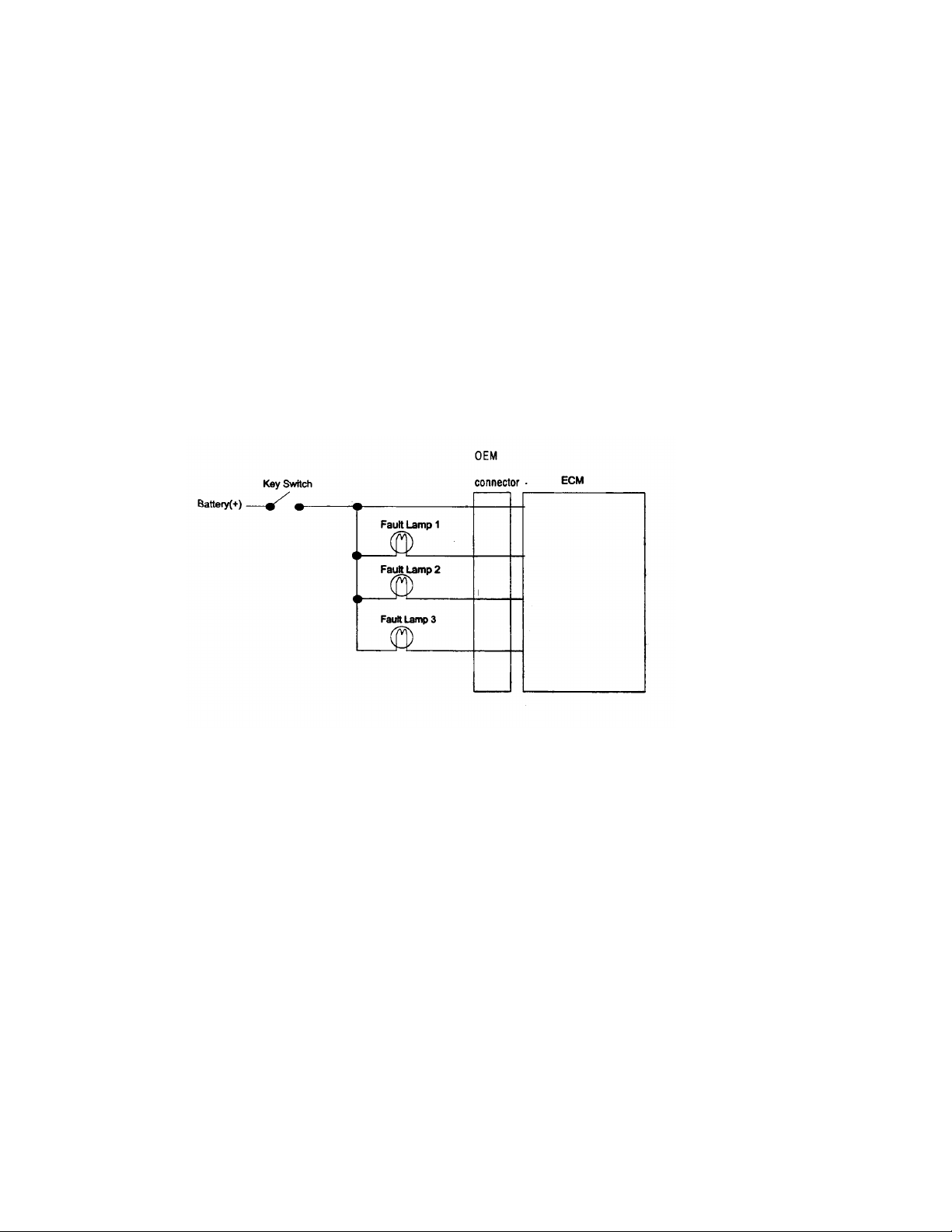
Fuses or fusible links set to 125 amps are advocated for the grid heating elements. The 24 V DC heater-relay is
connected to the OEM interface connector. The ECM can source up to 3 amps to turn this relay on. The switch
contact of this relay must carry the current from battery (+) to the grid heating elements. Only one relay is
required to drive both grid heaters on 24 V DC systems since the grid heaters are wired in series.
QSM11, QSX15
The intake air heater system is used to aid in starting during cold temperatures and to reduce white smoke after
such a start. The system consists of one heater elements that are controlled by the ECM via one high current
relay.
Note: The installer is responsible for procuring and mounting the grid heater power relays in an
acceptable location in respect to vibration and environmental influences such as road splash. The intake
air heater relays must not be mounted on engine.
The gauge of the wire from the grid heater, relays to the grid heater elements, also need to be sized for the
heater's current requirement. Typically, a 6 AWG minimally to carry the required current. Fuses or fusible links
set to 125 amps are advocated for the grid heating elements. The 24 V DC heater-relay is connected to the OEM
interface connector. The ECM can source up to 3 amps to turn this relay on. The switch contact of this relay
must carry the current from battery (+) to the grid heating elements. Only one relay is required to drive both grid
heaters on 24 V DC systems since the grid heaters are wired in series.
The QSM11 grid heater requires that the installer provide the ground wire or strap. This ground wire should be
routed directly to the starter ground connection or the battery ground. It is not acceptable to ground the grid
heater to the engine block or cylinder head.
The QSX15 grid heater is grounded directly to the engine's ground lug. The QSX15 grounding wire is supplied
with the engine.
QST 30
The intake air heater system is used to aid in starting during cold temperatures, while helping to reduce white
smoke. The system consists of twelve heater elements that are controlled by a primary and secondary ECM via
two high current relays. The ECM can source up to 3 amps.
Note: The installer is responsible for routing battery (+) connections to the contacts of the grid heater
relays, which are shipped with each engine.
Each grid heater element is rated for 86A@12V. As a result, each bank of grid heater elements will draw 258
amps in an ideal 24-volt system and have a total current draw of 512 amps for both banks. Therefore, the
AEB15.44
Alternator
Cylinder
Block
Starter
Battery
(+)
ECM
(+)
(+)
OOOO(+)
O
.
.
Optional
Cylinder Block or
2 AWG Flat Braided
Battery
Disconnect
Page 4 of 38
equipment manufacturer must be sure to size the supply wire appropriately to support the grid heater current draw
requirements. A minimum #000 gauge cable routed to each bank is recommended.
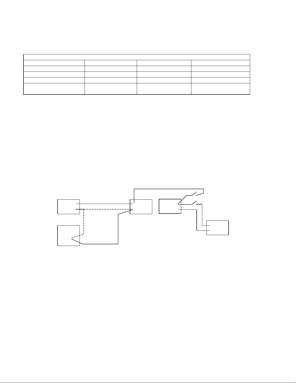
Engine Family Voltage Heater Current ECM Relay Source
QSB/QSC/QSL9 12 210 3 Amps
QSB/QSC/QSL9 24 105 3 Amps
QSM11 24 90 2 Amps
QSX15 24 105 2 Amps
QST30 24 258 amps/bank
512 amps total
3 Amps
Section II - Power and Ground Requirements
Power and Ground
System Grounding Requirements - Ground loops and electrical noise is a source of numerous problems with
today's electronic engines. For example, a high current device such as an alternator can inject electromagnetic
interference (EMI) through the cylinder block back through the ECM, which is case-grounded to the block to shunt
radio frequency noise. Other examples are relays that switch at high speeds introducing high frequency noise
into the cylinder block, which can introduce noise into the ECM. To minimize these problems, follow the practices
described in interface specification IS-1377-9807 and the following paragraphs. Refer to the Power Connection
Layout figure below.
.O.
(-)OO
Starter Negative
Power Connection Layout
High-Current Accessory Grounds - Alternators and other engine accessories greater than 10 amps should be
grounded to the starter negative terminal (always follow starter manufacturer's recommendations) rather than to
the cylinder block. This minimizes the electrical noise and ground loops present in the overall system. Optional
locations are to the battery negative terminal or a central location on the cylinder block. If the alternator is
grounded to a central location on the cylinder block, e.g. ground stud or ground boss, it must be attached to the
same location as the starter or battery negative.
Cylinder Block as Ground - The cylinder block represents a very large capacitance to system ground, which
makes it a highly effective RF shunt. Therefore, many devices, including the engine ECM, prefer to shunt RF
noise to the cylinder block. However, if the block contains current-induced voltage noise, it can become a point of
noise entry for devices using it as a RF shunt. It is acceptable to use the cylinder block as a return for devices
that are powered continuously. For devices that carry high currents (engine accessories greater than 10 amps) or
that switch on and off rapidly, the return should route to starter or battery negative.
(-)
(-)
(-)
O

AEB15.44
Page 5 of 38
Starter Ground - Ground the starter negative with a 2 AWG wire or larger to the cylinder block to help shunt RD
noise. A flat, braided wire is more effective than a round, stranded cable. An insulated welding cable is also
acceptable. Since the braided wire is not insulated, the welding cable is acceptable and typically has a longer
service life. This low impedance ground path design should take into account long-term degradation.
Frame Returns - Cab and chassis components should have common ground points to reduce ground loops.
Frame ground returns are often a source of problems and should be avoided. The frame ground alternative adds
more resistance to a return circuit.
Minimum wire size – The preferred method of connecting the ECM power supply to the batteries is by
maintaining the required number of stranded 18 AWG wires over the entire length of the connection (see each
engine family wiring diagram). When splices occur, a minimum of four stranded 10 AWG or larger wires must be
used between the splices and the battery, two for (+) and two for (-). Circuit resistance must not exceed 40
milliohms, but 10 milliohms is desirable. This circuit resistance limit includes the OEM-supplied circuit protection
system and any switches or interconnects.
Switches and Sensors Grounding Requirements
All switches and sensors that are wired directly to the ECM must be referenced to an ECM switch return. These
components use inputs that are susceptible to noise and voltage offsets that can be introduced through the return
path. Follow these guidelines when designing the machine wiring.
Inductive Load Sharing - When used as a switch return, an ECM switch return must never be used to return
unsuppressed inductive loads. Relay coils on the same circuit should be avoided. However, if a relay is used, it
should contain a suppression diode. This will isolate noise from the return, which can impair the reliability of a
switch or sensor input.
Sensor Dedication - When used as a return for certain analog sensors (i.e. pressure, temperature, or APS), an
ECM switch return should be dedicated solely to that sensor. Radiometric and resistive ECM inputs are very
sensitive, even a small change in voltage drop will affect the detected parameter.
Isolation - An ECM switch return must be kept isolated from machine chassis ground. This will prevent
undesirable ground loops.
Sourcing - An ECM switch return should not be used to return any voltage that has not been sourced from the
ECM. This will prevent overloading of the ECM supply returns.
Star Ground - For switch panels that contain critical switches such as the MUS on/off switch, it is good practice to
establish a "star" ground fed by dual redundant ECM switch returns. A proper star ground will have a separate
return to each switch. When designed in this manner, a single-point open-circuit return fault will result in the loss
of no more than one switch.
Solenoid Grounding Requirements
Solenoids and relay coils that are wired directly to the ECM may be referenced either to a good chassis ground or
to an ECM solenoid return. The ECM solenoid return is a convenience and is not a requirement. If an ECM
solenoid return is used, follow these guidelines when designing the machine wiring.
Inductive Load Sharing - When used as a solenoid return, an ECM solenoid return must not be used as a return
for critical components such as switches or sensors. Guidelines for these components are more extensive as
detailed in the previous paragraphs.
Isolation - An ECM solenoid return must be kept isolated from machine chassis ground. This will prevent
undesirable ground loops.
Sourcing - An ECM switch return should not be used to return any voltage that has not been sourced from the
ECM. This will prevent overloading of the ECM supply returns.
AEB15.44
Page 6 of 38
Section III - Keyswitch Requirement
Keyswitch Connection Requirements
Proper connections of the keyswitch to the ECM are critical for proper operation of the engine. The keyswitch
signal must be continuously present in order for the engine to operate. A loss of this signal, even a momentary
loss, can cause undesirable ECM resets, which can stall the engine and cause fault codes. Follow the installation
guidelines in interface specification IS-1377-9807 and the following paragraphs.
Sourcing - The keyswitch must be connected directly to the ECM. There must be no switches or relay contacts
between the keyswitch and the pinouts at ECM connector. Any engine shutdown systems designed to interrupt
key switch power must have a Cummins application review completed and approved for that system.
Fusing - The keyswitch signal must be fused so that an electrical short due to some other component does not
affect voltage at the ECM keyswitch input.
Inductive Load Sharing - The keyswitch signal must not share its circuit with unsuppressed inductive loads.
Relay coils on the same circuit should be avoided. However, if a relay is used, it should contain a suppression
diode. This will isolate noise, which can impair the reliability of the keyswitch input.
Lamp/Keyswitch Wiring Configuration
Fault
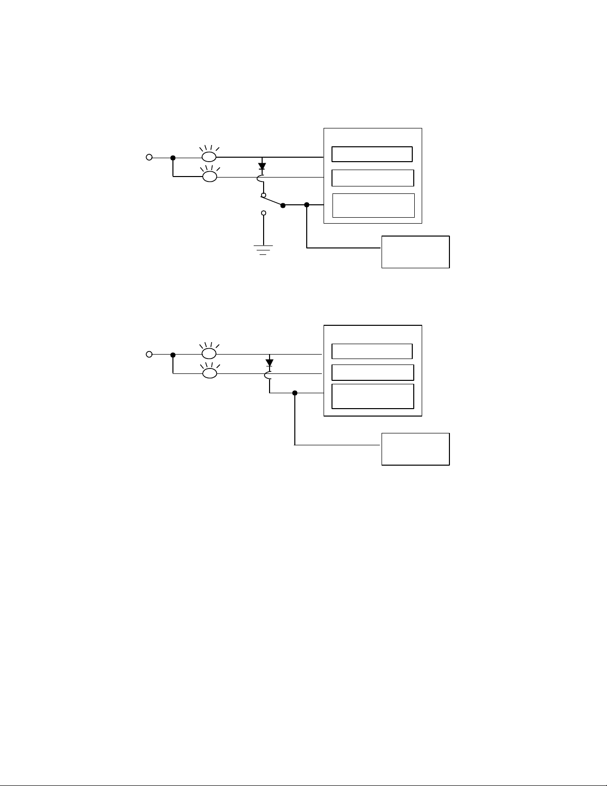
AEB15.44
DIAGNOSTIC
ENGINE PROTECTION
TO VEHICLE
(WHEN USED
)
STOP LAMP DRIVE
ENGINE PROTECTION
KEYSWITCH
(WHEN USED
)
Page 7 of 38
Optional - 2 Lamp Strategy - QSK19/45/60 - The Optional 2-lamp strategy will eliminate the Engine Protection
(white) Lamp. Therefore, the operator will only have a warning (yellow) and stop (red) lamp on the dashboard. All
of the faults that were mapped to the Engine protection lamp will become annunciated through the stop (red)
lamp. This change will only affect the wiring of the fault lamps and not the software or calibration. See wiring
below.
ENGINE ECU
KEYSWITCH
POWER
STOP LAMP DRIVE
WARNING LAMP DRIVE
POWER
SWITCH
LAMP DRIVE
2-Lamp Strategy with Cense
CENSE ECU
WARNING LAMP DRIVE
LAMP DRIVE
2-Lamp Strategy without Cense
PROPEL CIRCUIT
TO VEHICLE
PROPEL CIRCUIT

AEB15.44
Page 8 of 38
Section IV - Welding Requirements
Welding
Welding on the engine or engine mounted components is not recommended. Cummins recommends
disconnecting all OEM connectors. Attach the welder ground cable no more than two feet from the part being
welded. Never connect the ground cable of the welder to the ECM.
Section V - OEM Harness and Harness Routing
Wire Selection
Wire selection is critical for proper operation of the engine. Follow these guidelines when designing the OEM
wiring harness.
Wire Size - The size requirement for the harness wiring is 18 AWG stranded wire, covered with GXL or TXL
insulation for all underhood wiring. Diameter range including insulation is 0.040-0.095 inches. This wire size and
insulation type is the only one tested and approved by Cummins with the Deutsch 50-pin connector.
Twisted Pairs - There are three sets of twisted-pair wires. The wires are twisted at a rate of one twist per inch
and are used with the Shaft Speed sensor, the tachometer and the J1587 datalink.
Twisted Triplets - There are three sets of twisted-triplet wires. The wires are twisted at the rate of one twist per
inch and are used with the base throttle, remote throttle, and variable throttle option of the Intermediate Speed
Control (ISC) feature.
Datalinks - A separate cable must be used on the J1939 datalink. Refer to SAE J1939/11 and J1939/13 for
detailed specifications on the datalink wire requirements. Refer to AEB 15.43 Datalink and Diagnostics.
Contacts and Connectors
The connection points of the OEM wiring harness must be adequately protected from vibration and moisture
intrusion. The design practices and manufacturing methods for typical 12- and 24- volt systems are not adequate
when the subsystem operates with low signal level electronics on some circuits. Follow the guidelines in the
following paragraphs.
Datalinks - The quantum electronic subsystem requires gold plating for the OEM connector terminals and any
J1939 and J1708 datalink connections.
Switches - The Quantum subsystem recommends that all switch contacts (except keyswitch) be gold flashed to
ensure reliable switching at low voltages and currents. Ring terminals may be either solder dipped or tin plated.
Follow the guidelines in interface specification IS-1377-9802.
Connectors - Chassis-mounted connectors should be environmentally sealed and, at a minimum, be tin-plated or
nickel-plated. A lubricant should be applied to connector terminal surfaces as an added safeguard for use with
tin-plated or nickel-plated contacts to reduce the risk of fretting corrosion. In the cab area, tin plating should be on
wire-to-wire and wire-to-switch interconnections. This is a minimum requirement.
Recommended Plating - A detailed review of the termination and connector uses is to be conducted with the
connector supplier. A sample of typical connector supplier recommendations for plating subsystems used in low
current signal applications is shown in the Recommended Plating Systems table.

AEB15.44
Page 9 of 38
Recommended Plating Systems Table
Surface Plating Underplating Terminal material
Gold, cobalt hardened Nickel, matte Brass
120-200 Knoop 180-300 Knoop
50-80 micro-inches 80-110 micro-inches
Tin, Matte Nickel, matte Brass
30-120 micro-inches 50-120 micro-inches
<250 micro-inches/pair
Plating Systems Not Recommended - The following plating systems are not recommended: Tin with >250
micro-inches per terminal pair (male + female interface), gold with no underplating barrier, brass, silver, and
copper.
Dissimilar Metals - The use of dissimilar metals for any terminal pair (male + female interface) is not
recommended. Use of dissimilar metals will cause galvanic corrosion, resulting in terminal pitting and premature
circuit failure.
Throttle Circuit - It is recommended that the connector terminal between the base throttle pedal and ECM be
gold plated. This recommendation also applies to the remote throttle circuit and the variable ISC throttle circuit.
OEM Sensor Circuit - It is recommended that the connector terminals between the OEM temperature sensor and
the ECM and between the OEM pressure sensor and the ECM, be gold plated.
Protective Covering
The protective covering for the OEM wiring harness should have high abrasion and cut resistance, continuous
temperature capability to 125o C (257o F) and intermittent temperature capability to 150o C (302o F). The material
should also have high chemical resistance to fuel, engine oil and engine coolant. The harness covering should
not strain the wire or the wire seal at the connector and typically should be terminated approximately 1/2 inch from
the connector shell. Convoluted tubing, woven braid, or overfoamed is recommended as protective covering.
Convoluted Tubing - If convoluted conduit is selected, nylon material should be specified. The material should
be slit lengthwise and have drainage provisions for fluids. Conduit ends should be secure to prevent unraveling.
Woven Braid - If woven braid is selected, the material should consist of a nylon core with a vinyl covering. The
covering should be a minimum of 12 picks per inch and a tight, non-slip covering over the cables should be
provided. The braid tail should be secured to prevent unraveling.
Harness Routing and Support
The physical routing and support of the OEM wiring harness should minimize strain in the wire seals and of all
connectors and should protect the harness from damage due to abrasion, heat and sharp objects. The harness
should be clamped at any location on the engine/machine where support is required to protect the harness from
strain damage. Wherever possible, wires associated with the OEM harness should be routed physically close to
metals connected to battery (-) (e.g. frame rails, engine block) to minimize electromagnetic interference with other
electronic subsystems in the vehicle. All wiring should be kept free from sharp bends around components that
can cause nicks, cuts or other damage. The harness should be routed away from sharp objects, exhaust system
components and other high temperature components.
AEB15.44
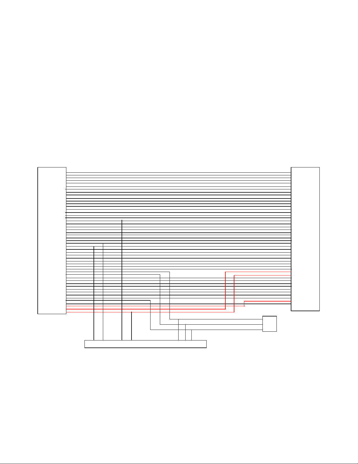
50 pin
Page 10 of 38
Section VI - Datalink Requirements for QSM11 and QSX15
The 9-pin service datalink does not ship on the QSM11 and QSX15 engine unless you order the designated EA
option. A 47-pin OEM Deutsch connector will also available as the interface instead of connecting directly to the
50-pin OEM connection on the ECM. This option will include a 9-pin connector, 3-pin connector, a 50-pin
connector and a 47- pin round connector. The new 47-pin OEM connector is in a mounting bracket generally
above the ECM. The 9 and 3 pin connectors are in the same location, but are not mounted into the bracket.
They come off the wiring harness extension. See wiring diagram below.
J1939 Backbone - A J1939 backbone is required on every machine that contains a QSM11 or QSX15 engine.
Terminating resistors should be used on the J1939 backbone as specified in AEB 15.43 Datalinks and
Diagnostics technical package. Recommended termination receptacles and stub connectors are defined in the
OEM Components technical package.
Stub Connector - A 3-pin J1939 receptacle stub connector must be inserted between the ECM and the J1939
OEM connector
on ECM
1
2
3
4
5
6
7
8
9
10
11
12
13
14
15
16
17
18
19
20
21
22
23
24
25
26
27
28
29
30
31
32
33
34
35
36
37
38
39
40
41
42
43
44
45
46
47
48
49
50
C
B
A
3 pin
G F B A E D C
9 pin Service Datalink
Connector
connector
for extending
J1939 backbone
47 pin
OEM connector
1
2
3
4
5
6
7
8
9
10
11
12
13
14
15
16
17
18
19
20
21
22
23
24
25
26
27
28
29
30
31
32
33
34
35
36
37
38
39
40
41
42
43
44
45
46
47
backbone. This is to prevent wiring faults between the ECM and the datalink connector from preventing
communication with the ECM, thus rendering it unserviceable. This stub must be located within 12 inches of the
50-pin OEM connector.
OEM Datalink option wiring diagram

 Loading...