

Page 1
Application
Engineering
Bulletin
Subject This AEB is for the following applications:
Installation Recommendations
Automotive Industrial Power Generation
Date April 2001 (Rev Dec 2001) Page 1 of 38 AEB Number 15.44
Engine Models included: QSB,QSC,QSL9,QSM11,QSX15,QSK19,QST30,QSK45,QSK60
Fuel Systems included:
Changes in blue
Introduction
The Quantum Installation Recommendations Technical Package was written to assist OEMs in integrating
Quantum engines into their equipment. This technical package includes the wiring diagram, pinouts, and other
pertinent information needed to install a Quantum engine
Refer to the following other Industrial AEB’s:
AEB 15.40 – Electronic Features
AEB 15.42 – OEM Components and Interfaces
AEB 15.43 – Datalinks and Diagnostics
Authors: Scott Decker, Michael L. Hill, Brian Landes, Jeffrey Martin, Stewart Sullivan, Tiffany Walker
Page 2

AEB15.44
Page 2 of 38
Table of Contents
Introduction ......................................................................................................................................... 1
Table of Contents................................................................................................................................. 2
Section I – Grid Heaters .................................................................................................................... 3-4
Section II – Power and Ground Requirements..................................................................................4-5
System Grounding Requirements ..................................................................................................... 4
High-Current Accessory Grounds ......................................................................................................4
Cylinder Block as Ground................................................................................................................. 4
Starter Ground .................................................................................................................................4
Frame Returns .................................................................................................................................4
Switches and Sensor Grounding Requirements................................................................................. 5
Solenoid Grounding Requirements.................................................................................................... 5
Section III – Keyswitch Requirements.................................................................................................. 6
Keyswitch Connection Requirements................................................................................................ 6
Sourcing.......................................................................................................................................... 6
Fusing............................................................................................................................................. 6
Inductive Load Sharing ..................................................................................................................... 6
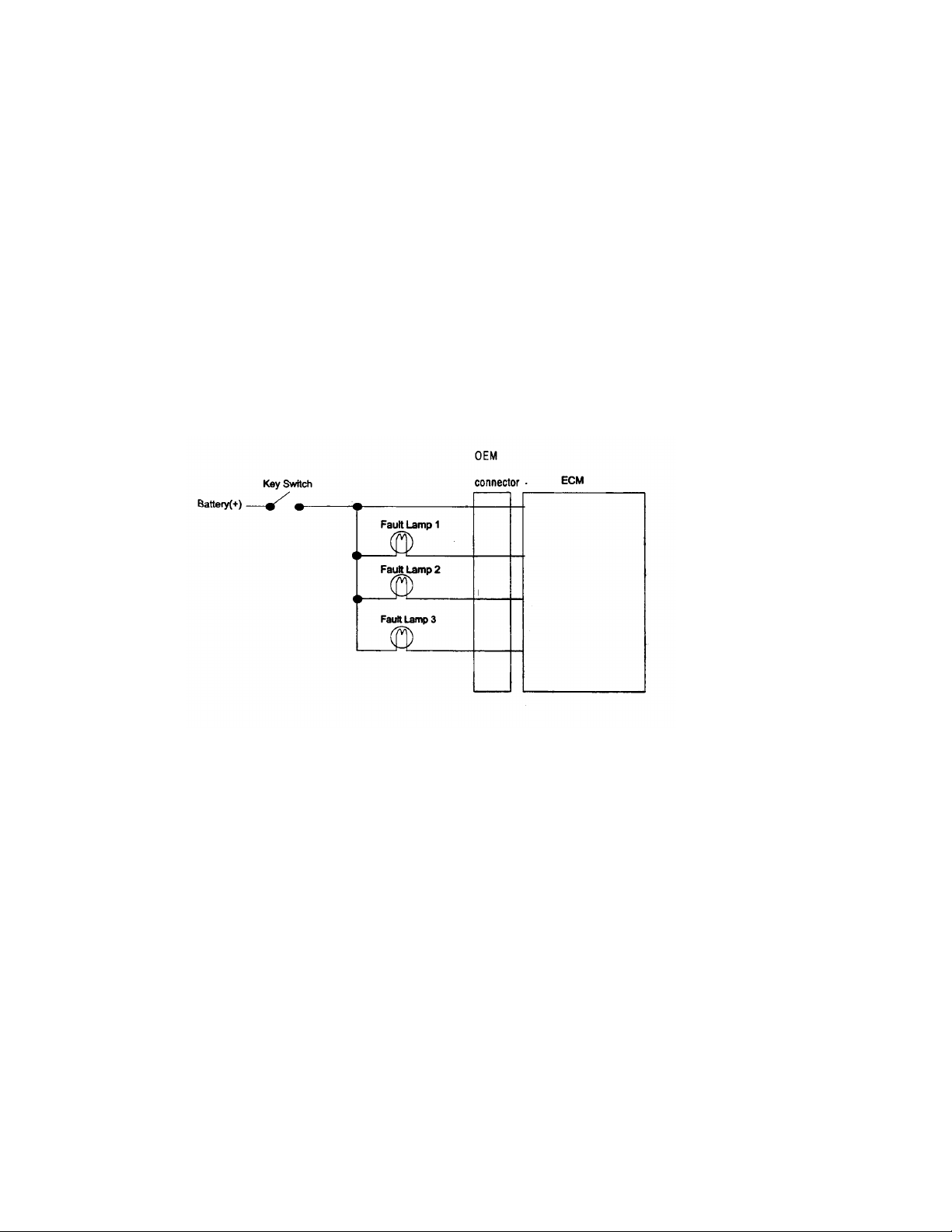
Fault Lamp/Keyswitch Wiring Configuration....................................................................................... 6
Optional 2-Lamp Strategy Wiring...................................................................................................... 6
Section IV – Welding Requirements..................................................................................................... 7
Section V – OEM Harness and Harness Routing ............................................................................... 7-8
Wire Section ....................................................................................................................................7
Contacts and Connectors ................................................................................................................. 7
Protective Covering ..........................................................................................................................8
Harness Routing and Support........................................................................................................... 8
Section VI – Datalink Requirements for QSM11 and QSX15 .................................................................9
Section VII – Wiring Diagrams/Pin Mapping ................................................................................. 10-18
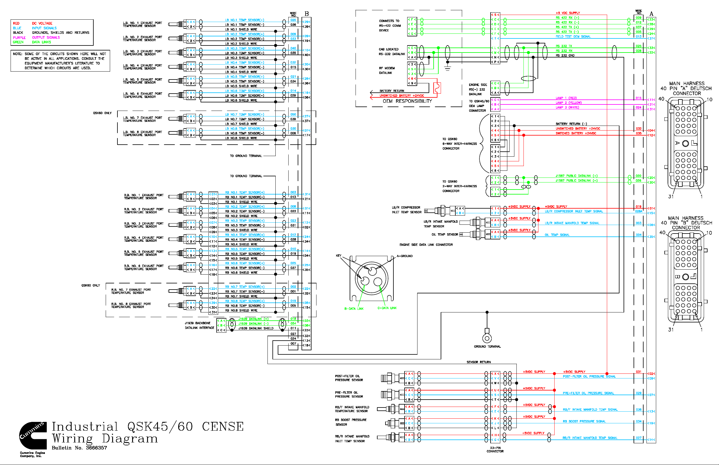
QSK45/60 Cense Wiring Diagram...................................................................................................10
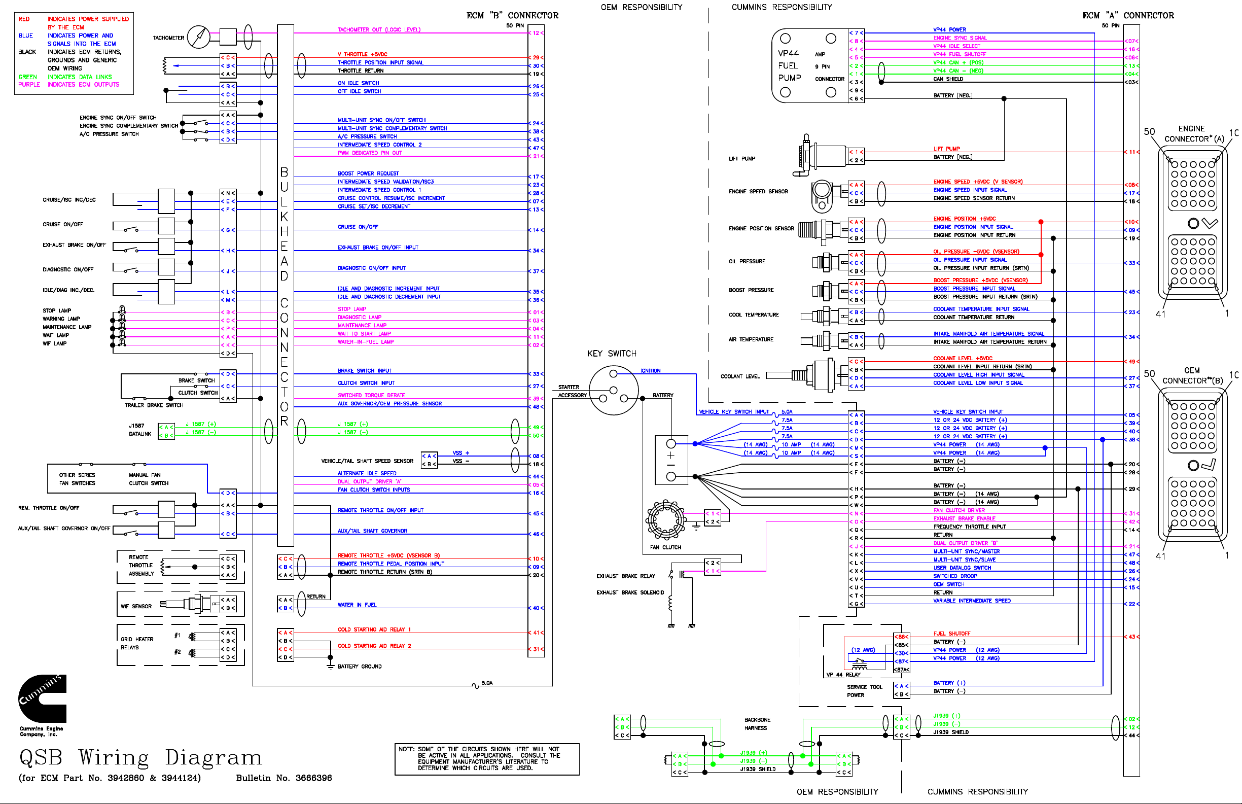
QSB Wiring Diagram ......................................................................................................................12
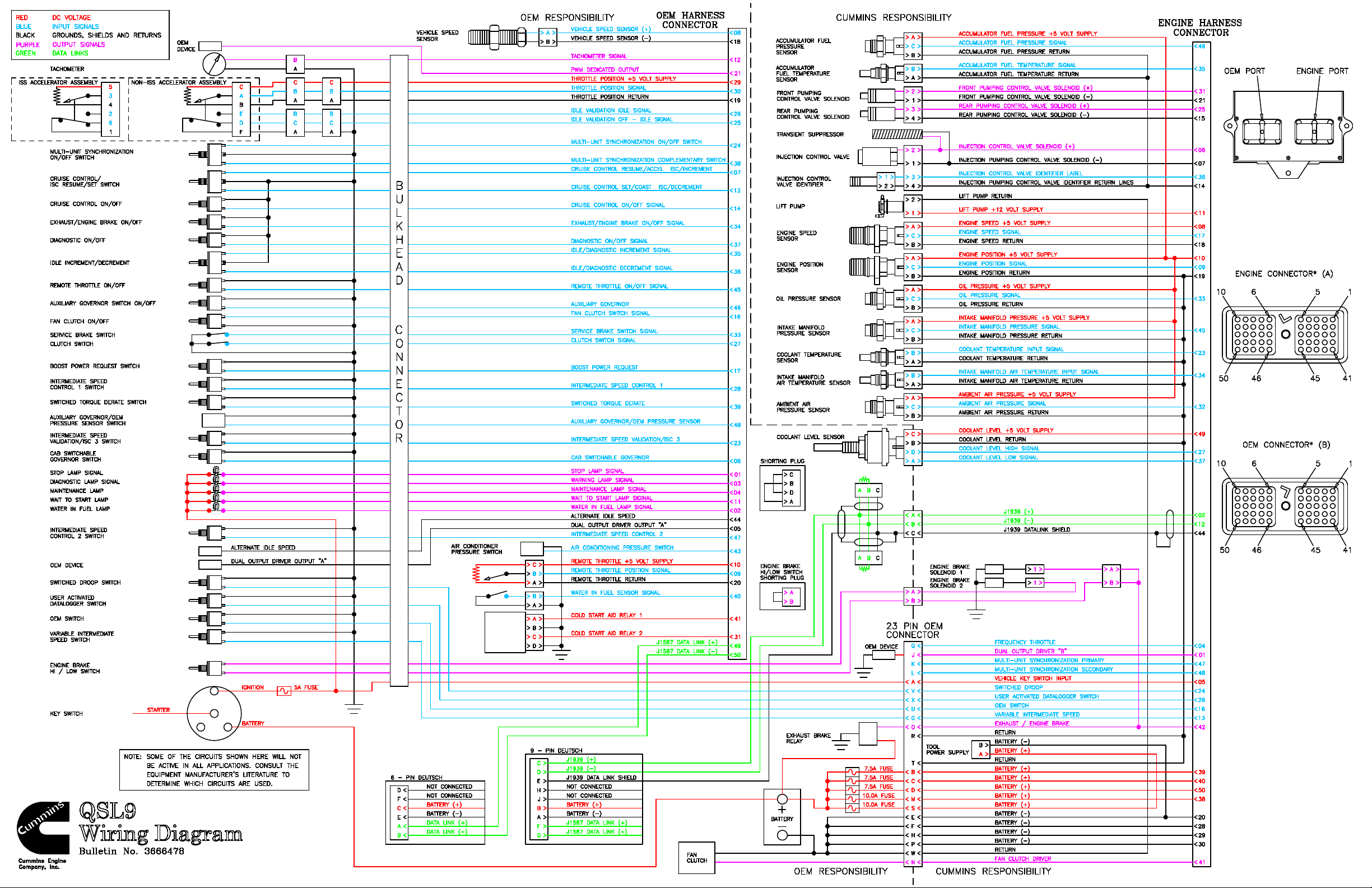
QSC Wiring Diagram......................................................................................................................14
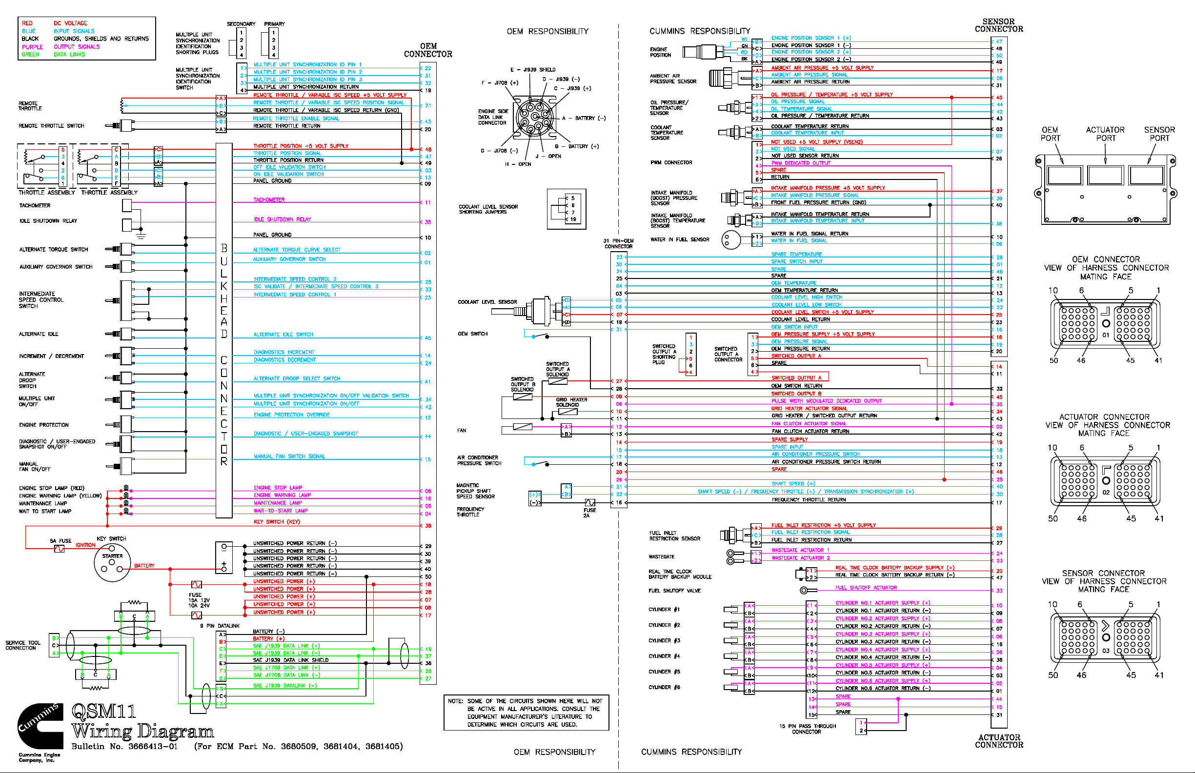
QSM11 Wiring Diagr am..................................................................................................................16
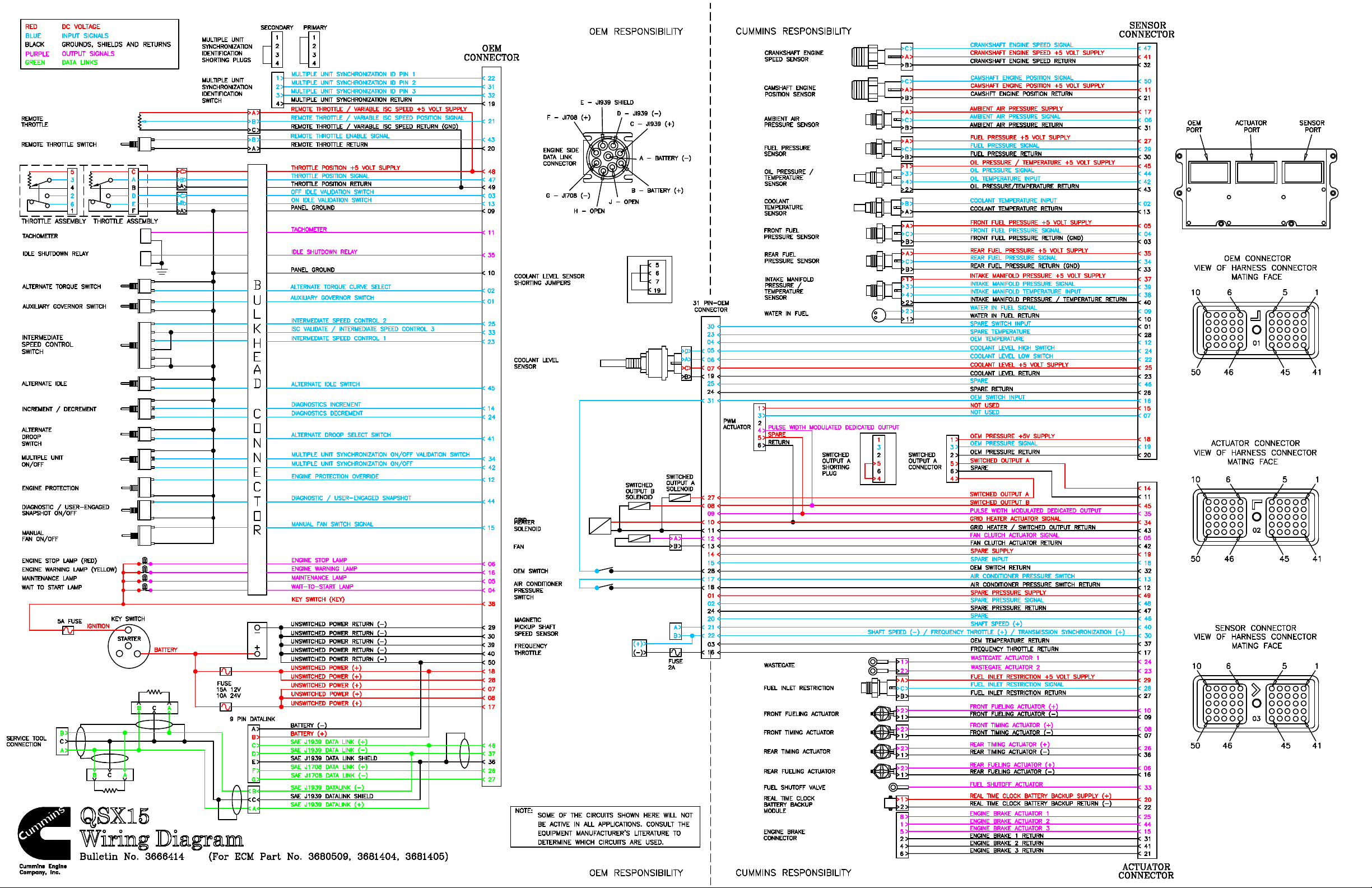
QSX15 Wiring Diagram..................................................................................................................18
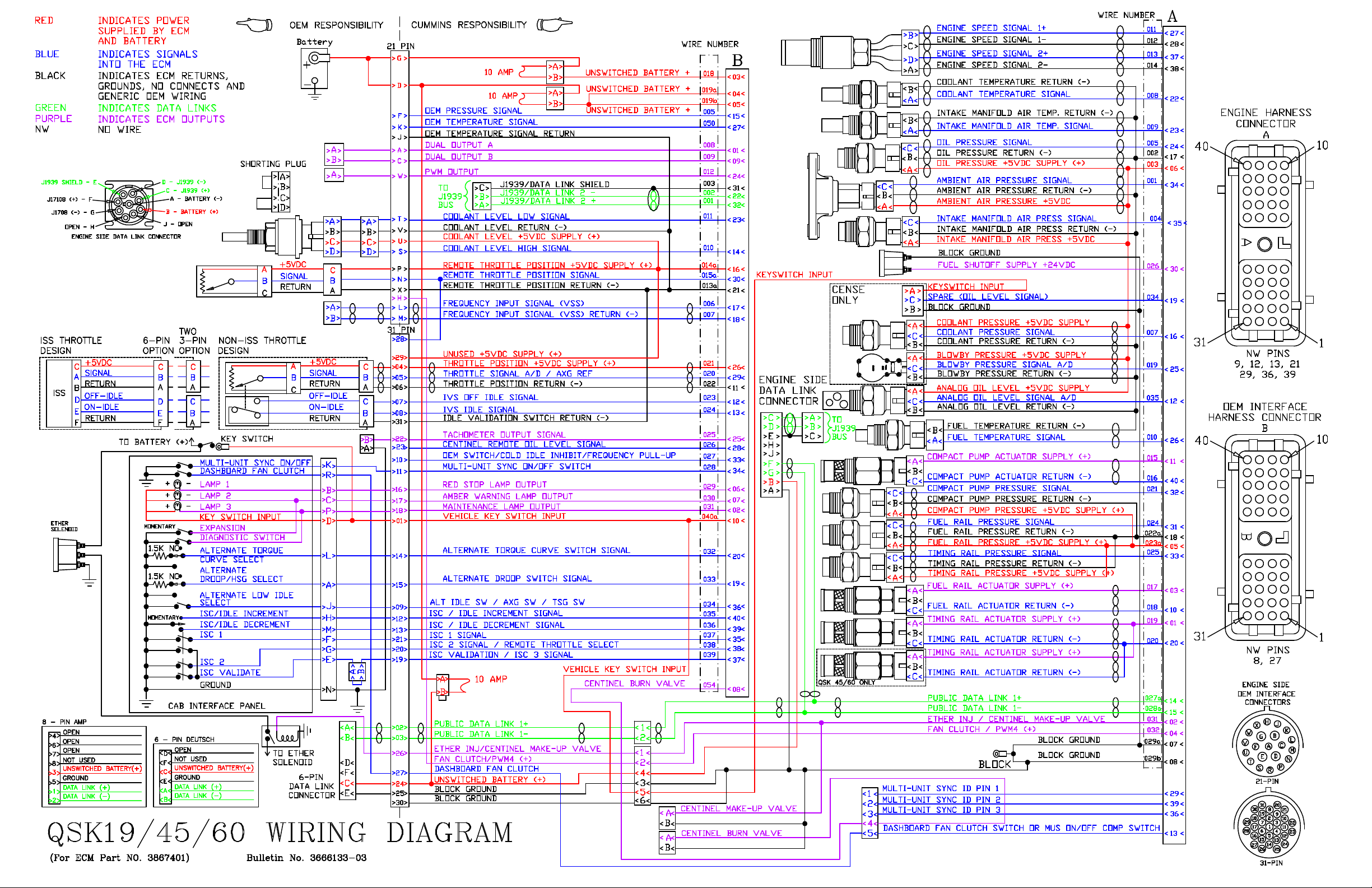
QSK19/45/60 Wiring Diagram .........................................................................................................20
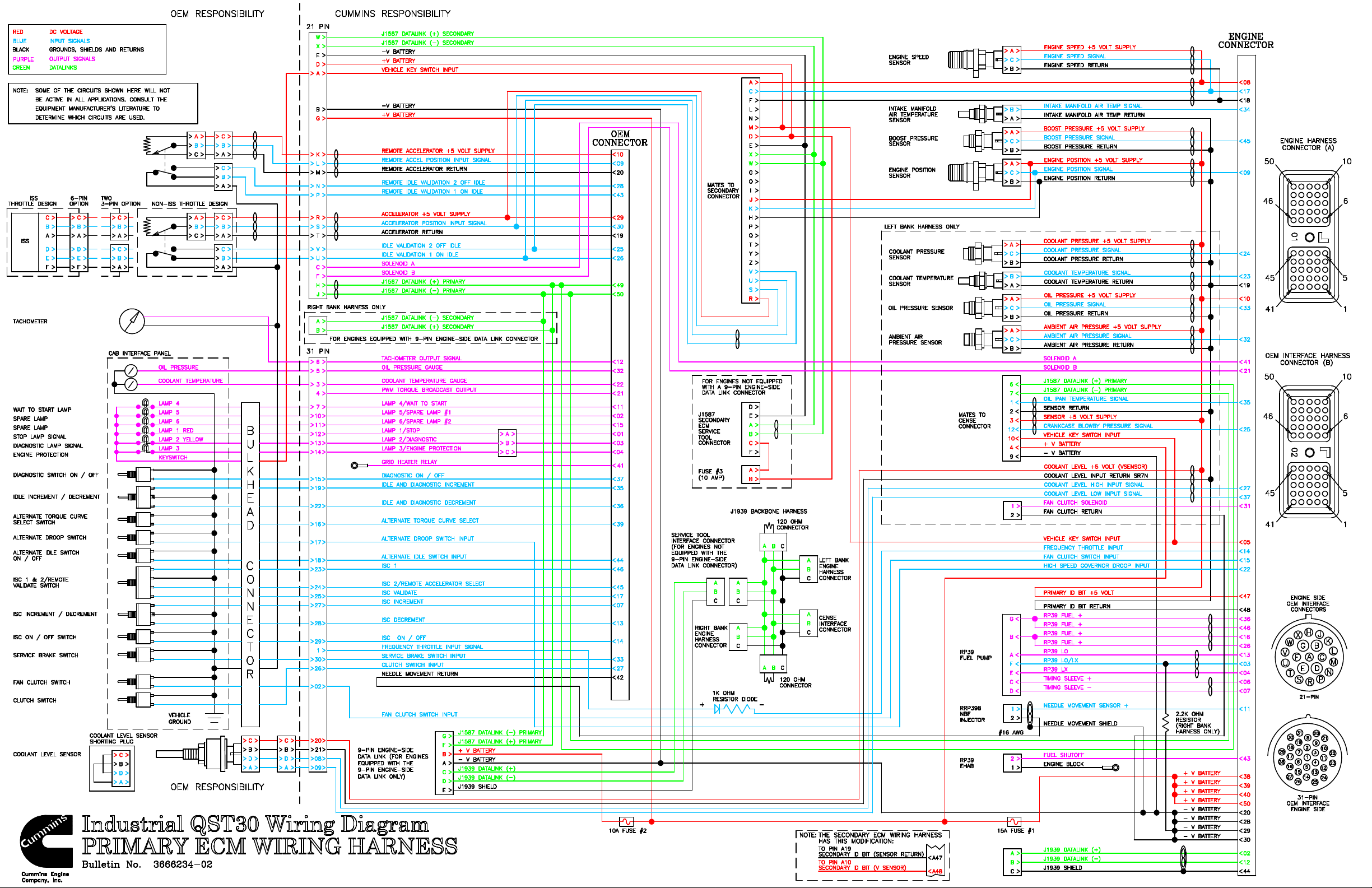
QST30 Wiring Diagram ..................................................................................................................22
QSB Pin Mapping ..........................................................................................................................24
QSC/QSL9 Pin Mapping............................................................................................................ 25-26
QSM11/QSX15 Pin Mapping..................................................................................................... 26-28
QSK19 Pin Mapping.................................................................................................................. 29-30
QST30 Pin Mapping .................................................................................................................. 30-31
Section VIII – Pinout Specifications.............................................................................................. 32-43
5V Sensor Voltage Source Pinout Specifications ..............................................................................32
5V Switched Pullup Input Pinout Specifications................................................................................33
10V Switched Pullup Input Pinout Specifications..............................................................................34
ECM Supply and Return Pinout Specifications.................................................................................35
Ratiometric Analog Input Pinout Specifications ................................................................................36
Resistive Analog Input Pinout Specifications ....................................................................................37
Switched Pulldown Input Pinout Specifications .................................................................................38
Switched Sink Driver Output Pinout Specifications ...........................................................................39
Switched Source Driver Output Pinout Specifications .......................................................................40
Tachometer Source Driver Output Pinout Specifi cations...................................................................41
Variable Reluctance Input Pinout Specifications (Differential Input)...................................................42
Variable Reluctance Input Pinout Specifications (Single-Ended Input)...............................................43
Page 3

AEB15.44
Page 3 of 38
Section I - Grid Heaters
QSB, QSC, QSL9
The intake air heater system is used to aid in starting during cold temperatures and to reduce white smoke after
such a start. The system consists of two heater elements that are controlled by the ECM via two high current
relays. Grid heaters are required for QSB/C/L9 engines.
Note: The installer is responsible for procuring and mounting the grid heater power relays in a location
free of road splash and also for routing battery connections through the relay contacts to the (2) grid
heaters which are shipped with the engines. The intake air heater relays must not be mounted on engine.
Since power routed to the grid heaters is through one wire then the gauge of the wire should be 2 AWG minimally
since each of the grid heating elements require 105 amps during the heating cycle. The gauge of the wire from
the grid heater, relays to the grid heater elements, also need to be 6 AWG minimally to carry the required current.
Fuses or fusible links set to 125 amps are advocated for the grid heating elements. The 24 V DC heater-relay is
connected to the OEM interface connector. The ECM can source up to 3 amps to turn this relay on. The switch
contact of this relay must carry the current from battery (+) to the grid heating elements. Only one relay is
required to drive both grid heaters on 24 V DC systems since the grid heaters are wired in series.
QSM11, QSX15
The intake air heater system is used to aid in starting during cold temperatures and to reduce white smoke after
such a start. The system consists of one heater elements that are controlled by the ECM via one high current
relay.
Note: The installer is responsible for procuring and mounting the grid heater power relays in an
acceptable location in respect to vibration and environmental influences such as road splash. The intake
air heater relays must not be mounted on engine.
The gauge of the wire from the grid heater, relays to the grid heater elements, also need to be sized for the
heater's current requirement. Typically, a 6 AWG minimally to carry the required current. Fuses or fusible links
set to 125 amps are advocated for the grid heating elements. The 24 V DC heater-relay is connected to the OEM
interface connector. The ECM can source up to 3 amps to turn this relay on. The switch contact of this relay
must carry the current from battery (+) to the grid heating elements. Only one relay is required to drive both grid
heaters on 24 V DC systems since the grid heaters are wired in series.
The QSM11 grid heater requires that the installer provide the ground wire or strap. This ground wire should be
routed directly to the starter ground connection or the battery ground. It is not acceptable to ground the grid
heater to the engine block or cylinder head.
The QSX15 grid heater is grounded directly to the engine's ground lug. The QSX15 grounding wire is supplied
with the engine.
QST 30
The intake air heater system is used to aid in starting during cold temperatures, while helping to reduce white
smoke. The system consists of twelve heater elements that are controlled by a primary and secondary ECM via
two high current relays. The ECM can source up to 3 amps.
Note: The installer is responsible for routing battery (+) connections to the contacts of the grid heater
relays, which are shipped with each engine.
Each grid heater element is rated for 86A@12V. As a result, each bank of grid heater elements will draw 258
amps in an ideal 24-volt system and have a total current draw of 512 amps for both banks. Therefore, the
Page 4
AEB15.44
Alternator
Cylinder
Block
Starter
Battery
(+)
ECM
(+)
(+)
OOOO(+)
O
.
.
Optional
Cylinder Block or
2 AWG Flat Braided
Battery
Disconnect
Page 4 of 38
equipment manufacturer must be sure to size the supply wire appropriately to support the grid heater current draw
requirements. A minimum #000 gauge cable routed to each bank is recommended.
Engine Family Voltage Heater Current ECM Relay Source
QSB/QSC/QSL9 12 210 3 Amps
QSB/QSC/QSL9 24 105 3 Amps
QSM11 24 90 2 Amps
QSX15 24 105 2 Amps
QST30 24 258 amps/bank
512 amps total
3 Amps
Section II - Power and Ground Requirements
Power and Ground
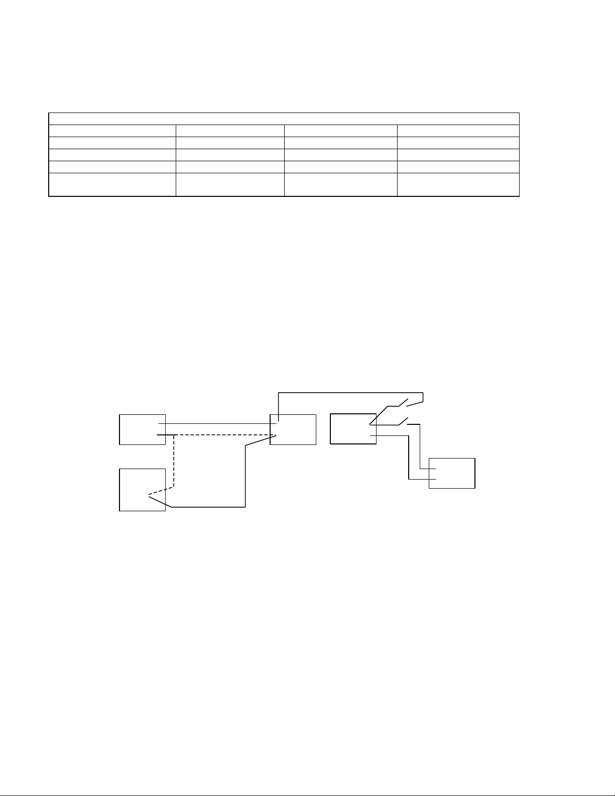
System Grounding Requirements - Ground loops and electrical noise is a source of numerous problems with
today's electronic engines. For example, a high current device such as an alternator can inject electromagnetic
interference (EMI) through the cylinder block back through the ECM, which is case-grounded to the block to shunt
radio frequency noise. Other examples are relays that switch at high speeds introducing high frequency noise
into the cylinder block, which can introduce noise into the ECM. To minimize these problems, follow the practices
described in interface specification IS-1377-9807 and the following paragraphs. Refer to the Power Connection
Layout figure below.
.O.
(-)OO
Starter Negative
Power Connection Layout
High-Current Accessory Grounds - Alternators and other engine accessories greater than 10 amps should be
grounded to the starter negative terminal (always follow starter manufacturer's recommendations) rather than to
the cylinder block. This minimizes the electrical noise and ground loops present in the overall system. Optional
locations are to the battery negative terminal or a central location on the cylinder block. If the alternator is
grounded to a central location on the cylinder block, e.g. ground stud or ground boss, it must be attached to the
same location as the starter or battery negative.
Cylinder Block as Ground - The cylinder block represents a very large capacitance to system ground, which
makes it a highly effective RF shunt. Therefore, many devices, including the engine ECM, prefer to shunt RF
noise to the cylinder block. However, if the block contains current-induced voltage noise, it can become a point of
noise entry for devices using it as a RF shunt. It is acceptable to use the cylinder block as a return for devices
that are powered continuously. For devices that carry high currents (engine accessories greater than 10 amps) or
that switch on and off rapidly, the return should route to starter or battery negative.
(-)
(-)
(-)
O
Page 5

AEB15.44
Page 5 of 38
Starter Ground - Ground the starter negative with a 2 AWG wire or larger to the cylinder block to help shunt RD
noise. A flat, braided wire is more effective than a round, stranded cable. An insulated welding cable is also
acceptable. Since the braided wire is not insulated, the welding cable is acceptable and typically has a longer
service life. This low impedance ground path design should take into account long-term degradation.
Frame Returns - Cab and chassis components should have common ground points to reduce ground loops.
Frame ground returns are often a source of problems and should be avoided. The frame ground alternative adds
more resistance to a return circuit.
Minimum wire size – The preferred method of connecting the ECM power supply to the batteries is by
maintaining the required number of stranded 18 AWG wires over the entire length of the connection (see each
engine family wiring diagram). When splices occur, a minimum of four stranded 10 AWG or larger wires must be
used between the splices and the battery, two for (+) and two for (-). Circuit resistance must not exceed 40
milliohms, but 10 milliohms is desirable. This circuit resistance limit includes the OEM-supplied circuit protection
system and any switches or interconnects.
Switches and Sensors Grounding Requirements
All switches and sensors that are wired directly to the ECM must be referenced to an ECM switch return. These
components use inputs that are susceptible to noise and voltage offsets that can be introduced through the return
path. Follow these guidelines when designing the machine wiring.
Inductive Load Sharing - When used as a switch return, an ECM switch return must never be used to return
unsuppressed inductive loads. Relay coils on the same circuit should be avoided. However, if a relay is used, it
should contain a suppression diode. This will isolate noise from the return, which can impair the reliability of a
switch or sensor input.
Sensor Dedication - When used as a return for certain analog sensors (i.e. pressure, temperature, or APS), an
ECM switch return should be dedicated solely to that sensor. Radiometric and resistive ECM inputs are very
sensitive, even a small change in voltage drop will affect the detected parameter.
Isolation - An ECM switch return must be kept isolated from machine chassis ground. This will prevent
undesirable ground loops.
Sourcing - An ECM switch return should not be used to return any voltage that has not been sourced from the
ECM. This will prevent overloading of the ECM supply returns.
Star Ground - For switch panels that contain critical switches such as the MUS on/off switch, it is good practice to
establish a "star" ground fed by dual redundant ECM switch returns. A proper star ground will have a separate
return to each switch. When designed in this manner, a single-point open-circuit return fault will result in the loss
of no more than one switch.
Solenoid Grounding Requirements
Solenoids and relay coils that are wired directly to the ECM may be referenced either to a good chassis ground or
to an ECM solenoid return. The ECM solenoid return is a convenience and is not a requirement. If an ECM
solenoid return is used, follow these guidelines when designing the machine wiring.
Inductive Load Sharing - When used as a solenoid return, an ECM solenoid return must not be used as a return
for critical components such as switches or sensors. Guidelines for these components are more extensive as
detailed in the previous paragraphs.
Isolation - An ECM solenoid return must be kept isolated from machine chassis ground. This will prevent
undesirable ground loops.
Sourcing - An ECM switch return should not be used to return any voltage that has not been sourced from the
ECM. This will prevent overloading of the ECM supply returns.
Page 6
AEB15.44
Page 6 of 38
Section III - Keyswitch Requirement
Keyswitch Connection Requirements
Proper connections of the keyswitch to the ECM are critical for proper operation of the engine. The keyswitch
signal must be continuously present in order for the engine to operate. A loss of this signal, even a momentary
loss, can cause undesirable ECM resets, which can stall the engine and cause fault codes. Follow the installation
guidelines in interface specification IS-1377-9807 and the following paragraphs.
Sourcing - The keyswitch must be connected directly to the ECM. There must be no switches or relay contacts
between the keyswitch and the pinouts at ECM connector. Any engine shutdown systems designed to interrupt
key switch power must have a Cummins application review completed and approved for that system.
Fusing - The keyswitch signal must be fused so that an electrical short due to some other component does not
affect voltage at the ECM keyswitch input.
Inductive Load Sharing - The keyswitch signal must not share its circuit with unsuppressed inductive loads.
Relay coils on the same circuit should be avoided. However, if a relay is used, it should contain a suppression
diode. This will isolate noise, which can impair the reliability of the keyswitch input.
Lamp/Keyswitch Wiring Configuration
Fault
Page 7
AEB15.44
DIAGNOSTIC
ENGINE PROTECTION
TO VEHICLE
(WHEN USED
)
STOP LAMP DRIVE
ENGINE PROTECTION
KEYSWITCH
(WHEN USED
)
Page 7 of 38
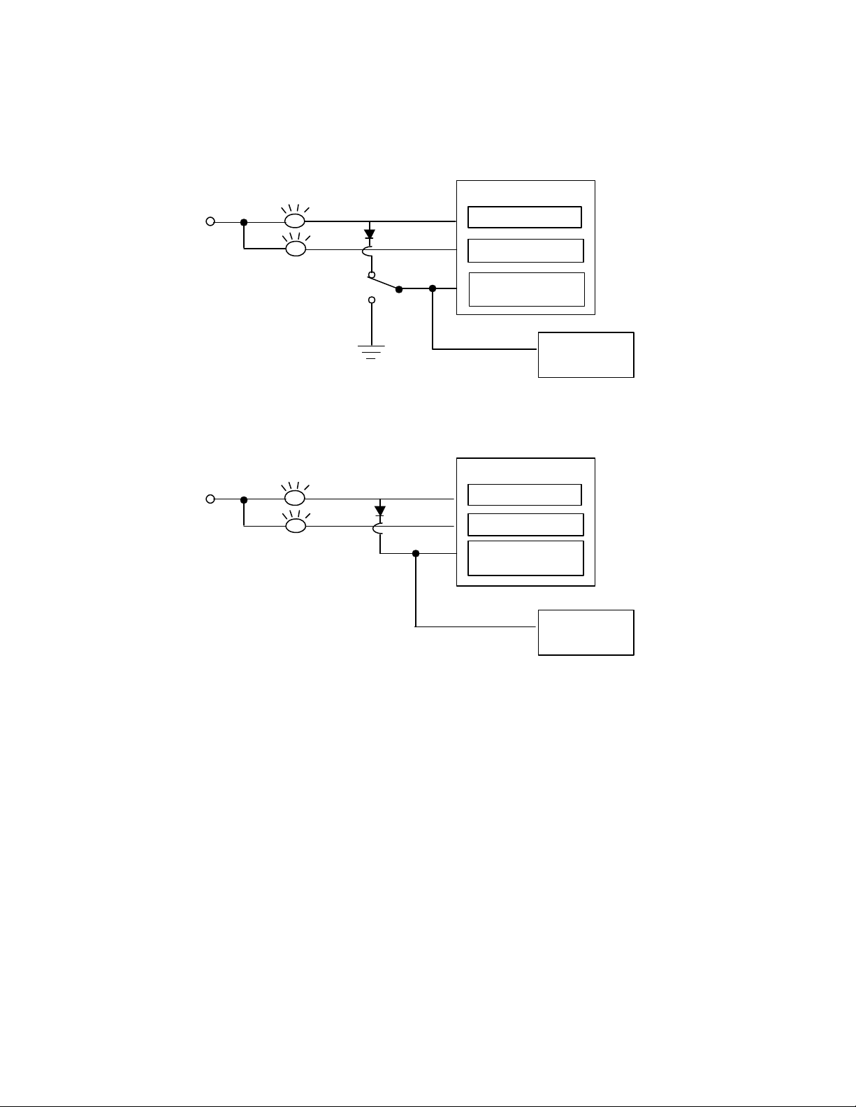
Optional - 2 Lamp Strategy - QSK19/45/60 - The Optional 2-lamp strategy will eliminate the Engine Protection
(white) Lamp. Therefore, the operator will only have a warning (yellow) and stop (red) lamp on the dashboard. All
of the faults that were mapped to the Engine protection lamp will become annunciated through the stop (red)
lamp. This change will only affect the wiring of the fault lamps and not the software or calibration. See wiring
below.
ENGINE ECU
KEYSWITCH
POWER
STOP LAMP DRIVE
WARNING LAMP DRIVE
POWER
SWITCH
LAMP DRIVE
2-Lamp Strategy with Cense
CENSE ECU
WARNING LAMP DRIVE
LAMP DRIVE
2-Lamp Strategy without Cense
PROPEL CIRCUIT
TO VEHICLE
PROPEL CIRCUIT
Page 8

AEB15.44
Page 8 of 38
Section IV - Welding Requirements
Welding
Welding on the engine or engine mounted components is not recommended. Cummins recommends
disconnecting all OEM connectors. Attach the welder ground cable no more than two feet from the part being
welded. Never connect the ground cable of the welder to the ECM.
Section V - OEM Harness and Harness Routing
Wire Selection
Wire selection is critical for proper operation of the engine. Follow these guidelines when designing the OEM
wiring harness.
Wire Size - The size requirement for the harness wiring is 18 AWG stranded wire, covered with GXL or TXL
insulation for all underhood wiring. Diameter range including insulation is 0.040-0.095 inches. This wire size and
insulation type is the only one tested and approved by Cummins with the Deutsch 50-pin connector.
Twisted Pairs - There are three sets of twisted-pair wires. The wires are twisted at a rate of one twist per inch
and are used with the Shaft Speed sensor, the tachometer and the J1587 datalink.
Twisted Triplets - There are three sets of twisted-triplet wires. The wires are twisted at the rate of one twist per
inch and are used with the base throttle, remote throttle, and variable throttle option of the Intermediate Speed
Control (ISC) feature.
Datalinks - A separate cable must be used on the J1939 datalink. Refer to SAE J1939/11 and J1939/13 for
detailed specifications on the datalink wire requirements. Refer to AEB 15.43 Datalink and Diagnostics.
Contacts and Connectors
The connection points of the OEM wiring harness must be adequately protected from vibration and moisture
intrusion. The design practices and manufacturing methods for typical 12- and 24- volt systems are not adequate
when the subsystem operates with low signal level electronics on some circuits. Follow the guidelines in the
following paragraphs.
Datalinks - The quantum electronic subsystem requires gold plating for the OEM connector terminals and any
J1939 and J1708 datalink connections.
Switches - The Quantum subsystem recommends that all switch contacts (except keyswitch) be gold flashed to
ensure reliable switching at low voltages and currents. Ring terminals may be either solder dipped or tin plated.
Follow the guidelines in interface specification IS-1377-9802.
Connectors - Chassis-mounted connectors should be environmentally sealed and, at a minimum, be tin-plated or
nickel-plated. A lubricant should be applied to connector terminal surfaces as an added safeguard for use with
tin-plated or nickel-plated contacts to reduce the risk of fretting corrosion. In the cab area, tin plating should be on
wire-to-wire and wire-to-switch interconnections. This is a minimum requirement.
Recommended Plating - A detailed review of the termination and connector uses is to be conducted with the
connector supplier. A sample of typical connector supplier recommendations for plating subsystems used in low
current signal applications is shown in the Recommended Plating Systems table.
Page 9

AEB15.44
Page 9 of 38
Recommended Plating Systems Table
Surface Plating Underplating Terminal material
Gold, cobalt hardened Nickel, matte Brass
120-200 Knoop 180-300 Knoop
50-80 micro-inches 80-110 micro-inches
Tin, Matte Nickel, matte Brass
30-120 micro-inches 50-120 micro-inches
<250 micro-inches/pair
Plating Systems Not Recommended - The following plating systems are not recommended: Tin with >250
micro-inches per terminal pair (male + female interface), gold with no underplating barrier, brass, silver, and
copper.
Dissimilar Metals - The use of dissimilar metals for any terminal pair (male + female interface) is not
recommended. Use of dissimilar metals will cause galvanic corrosion, resulting in terminal pitting and premature
circuit failure.
Throttle Circuit - It is recommended that the connector terminal between the base throttle pedal and ECM be
gold plated. This recommendation also applies to the remote throttle circuit and the variable ISC throttle circuit.
OEM Sensor Circuit - It is recommended that the connector terminals between the OEM temperature sensor and
the ECM and between the OEM pressure sensor and the ECM, be gold plated.
Protective Covering
The protective covering for the OEM wiring harness should have high abrasion and cut resistance, continuous
temperature capability to 125o C (257o F) and intermittent temperature capability to 150o C (302o F). The material
should also have high chemical resistance to fuel, engine oil and engine coolant. The harness covering should
not strain the wire or the wire seal at the connector and typically should be terminated approximately 1/2 inch from
the connector shell. Convoluted tubing, woven braid, or overfoamed is recommended as protective covering.
Convoluted Tubing - If convoluted conduit is selected, nylon material should be specified. The material should
be slit lengthwise and have drainage provisions for fluids. Conduit ends should be secure to prevent unraveling.
Woven Braid - If woven braid is selected, the material should consist of a nylon core with a vinyl covering. The
covering should be a minimum of 12 picks per inch and a tight, non-slip covering over the cables should be
provided. The braid tail should be secured to prevent unraveling.
Harness Routing and Support
The physical routing and support of the OEM wiring harness should minimize strain in the wire seals and of all
connectors and should protect the harness from damage due to abrasion, heat and sharp objects. The harness
should be clamped at any location on the engine/machine where support is required to protect the harness from
strain damage. Wherever possible, wires associated with the OEM harness should be routed physically close to
metals connected to battery (-) (e.g. frame rails, engine block) to minimize electromagnetic interference with other
electronic subsystems in the vehicle. All wiring should be kept free from sharp bends around components that
can cause nicks, cuts or other damage. The harness should be routed away from sharp objects, exhaust system
components and other high temperature components.
Page 10
AEB15.44
50 pin
Page 10 of 38
Section VI - Datalink Requirements for QSM11 and QSX15
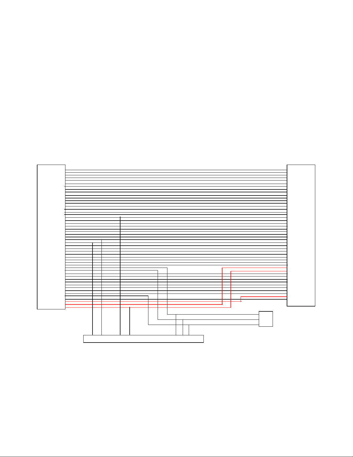
The 9-pin service datalink does not ship on the QSM11 and QSX15 engine unless you order the designated EA
option. A 47-pin OEM Deutsch connector will also available as the interface instead of connecting directly to the
50-pin OEM connection on the ECM. This option will include a 9-pin connector, 3-pin connector, a 50-pin
connector and a 47- pin round connector. The new 47-pin OEM connector is in a mounting bracket generally
above the ECM. The 9 and 3 pin connectors are in the same location, but are not mounted into the bracket.
They come off the wiring harness extension. See wiring diagram below.
J1939 Backbone - A J1939 backbone is required on every machine that contains a QSM11 or QSX15 engine.
Terminating resistors should be used on the J1939 backbone as specified in AEB 15.43 Datalinks and
Diagnostics technical package. Recommended termination receptacles and stub connectors are defined in the
OEM Components technical package.
Stub Connector - A 3-pin J1939 receptacle stub connector must be inserted between the ECM and the J1939
OEM connector
on ECM
1
2
3
4
5
6
7
8
9
10
11
12
13
14
15
16
17
18
19
20
21
22
23
24
25
26
27
28
29
30
31
32
33
34
35
36
37
38
39
40
41
42
43
44
45
46
47
48
49
50
C
B
A
3 pin
G F B A E D C
9 pin Service Datalink
Connector
connector
for extending
J1939 backbone
47 pin
OEM connector
1
2
3
4
5
6
7
8
9
10
11
12
13
14
15
16
17
18
19
20
21
22
23
24
25
26
27
28
29
30
31
32
33
34
35
36
37
38
39
40
41
42
43
44
45
46
47
backbone. This is to prevent wiring faults between the ECM and the datalink connector from preventing
communication with the ECM, thus rendering it unserviceable. This stub must be located within 12 inches of the
50-pin OEM connector.
OEM Datalink option wiring diagram
Page 11
Page 12

Page 13
Page 14
Page 15
Page 16
Page 17
Page 18
Page 19

Page 19 of 38
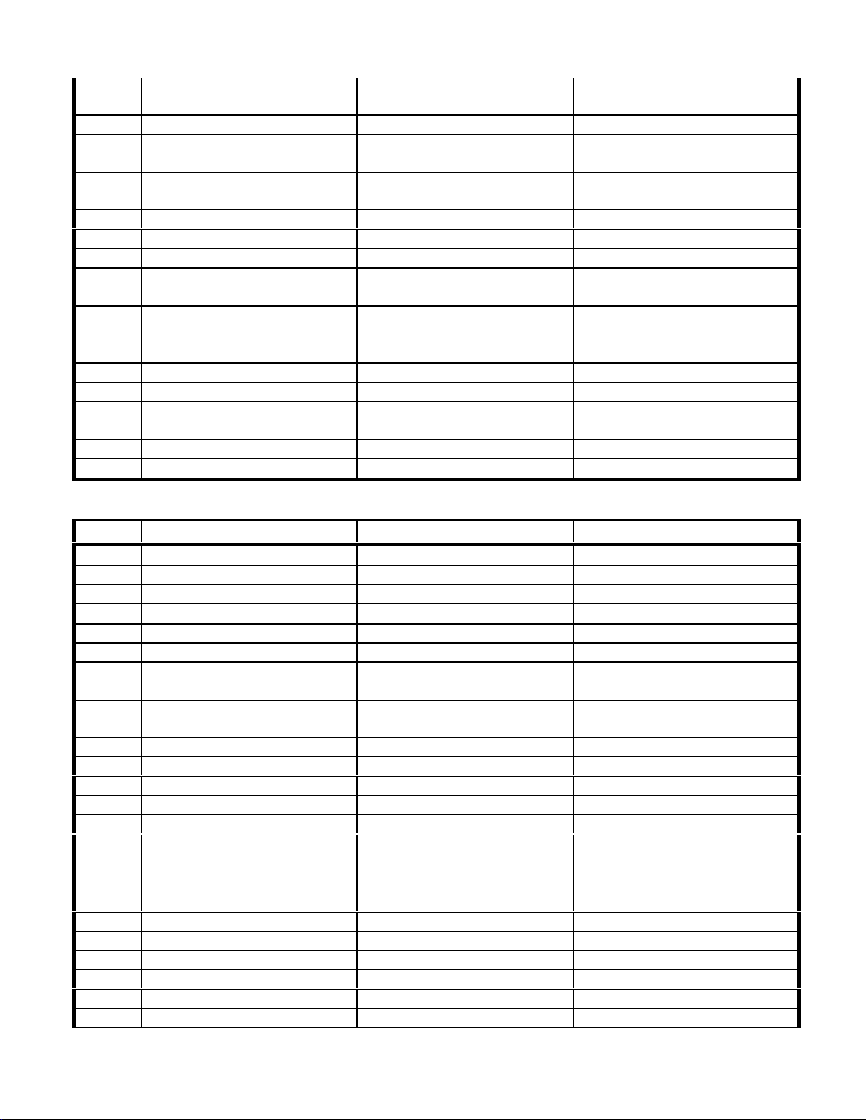
Pin Mapping
QSB - OEM 50 Pin connector
Pin Pinout Type Signal Name Feature
1 600 mA current sink to ground Stop Lamp Engine Protection/Diagnostics
2 600 mA current sink to ground Water In Fuel Lamp Water-In-Fuel
3 600 mA current sink to ground Diagnostic Lamp Diagnostics
4 600 mA current sink to ground Maintenance Lamp Diagnostics
5 600 mA current sink to ground Dual Output Driver A Dual Outputs
AEB15.44
7 <50 ohm Closed, 50Kohm Open Cruise Control/ISC Increment/
ISC Resume
8 Vehicle/Tail Shaft Speed Sensor Vehicle Speed Sensor Positive
Input
9 Remote Throttle Sensor Remote Throttle Analog Input Remote Throttle
10 Remote throttle (VsensorB) Remote Throttle +5Vdc Remote Throttle
11 600 mA current sink to ground Wait to Start Lamp Intake Air Heater/Grid Heater
12 Frequency Output Tachometer Out (Logic Level) Tachometer
13 <50 ohm Closed, 50Kohm Open Cruise Set/ISC Decrement Cruise Control/ISC Decrement
14 <50 ohm Closed, 50Kohm Open Cruise On/Off Cruise Control
Cruise Control/ISC Increment
Vehicle Speed
15 Reserved
16 <50 ohm Closed, 50Kohm Open Fan Clutch Switch Inputs Fan Clutch
17 <50 ohm Closed, 50Kohm Open Boost Power Request Switch Boost Power
18 Vehicle Speed Sensor Vehicle Speed Sensor Negative
Input
19 Ground Throttle Return Throttle
20 Ground Remote Throttle Return Remote Throttle
21 3 amps Dedicated PWM Output Dedicated PWM
22 Reserved
23 <50 ohm Closed, 50Kohm Open ISC 3 / ISC Validation Switch Intermediate Speed Control
24 50 ohm Closed, 50Kohm Open Multi-Unit Sync On/Off Switch
Input
25 125 ohm Closed, 50 Mohm Open Off Idle Switch Idle Validation
26 <125 ohm Closed, 50 Mohm
Open
27 <50 ohm Closed, 50Kohm Open Clutch Switch Input Exhaust Brakes
28 <50 ohm Closed, 50Kohm Open ISC 1 Switch Intermediate Speed Control
29 +5 Vdc supply Throttle\Potentiometer +5 Vdc Throttle
30 Throttle Position Sensor Throttle Position Input Signal Throttle
31 1 amp, Hi side Drive Cold Starting Aid Relay 2 Intake Air Heater/Grid Heater
32 Reserved
On Idle Switch Idle Validation
Vehicle Speed
Multi-Unit Sync
33 <50 ohm Closed, 50Kohm Open Brake Switch Exhaust Brakes
34 <50 ohm Closed, 50Kohm Open Exhaust Brake On/Off Switch Exhaust Brakes
35 <50 ohm Closed, 50Kohm Open Idle and Diagnostic Increment
Switch
Diagnostics, Low Idle Gov.
Page 20
Page 20 of 38
AEB15.44
36 <50 ohm Closed, 50Kohm Open Idle and Diagnostic Decrement
Switch
37 <50 ohm Closed, 50Kohm Open Test (Diagnostic) On/Off Switch Diagnostics
38 <50 ohm Closed, 50Kohm Open Multi-Unit Sync Complementary
Switch
39 A/D Input Alternate Torque Derate Switch
Input
40 Water In Fuel Sensor Water In Fuel Sensor Water-In-Fuel
41 1 amp, Hi side drive Cold Starting Aid Relay1 Intake Air Heater/Grid Heater
42 Reserved
43 <125 ohm Closed, 50 Mohm
Open
44 <50 ohm Closed, 50Kohm Open Alternate Idle Speed Switch Input Alternate Idle
45 <50 ohm Closed, 50Kohm Open Remote Throttle On/Off Switch Remote Throttle
46 Switch (Pulled up) Aux. Governor On/Off Switch Auxiliary Speed Governor
47 <50 ohm Closed, 50Kohm Open ISC 2 Switch Intermediate Speed Control
48 A/D Input OEM Pressure Sensor OEM Pressure
49 Datalink J1708/J1587 Datalink + J1587 Datalink
50 Datalink J1708/J1587 Datalink - J1587 Datalink
A/C Pressure Switch Fan Clutch
Diagnostics, Low Idle Gov., ISC
Multi-Unit Sync
Alternate Torque
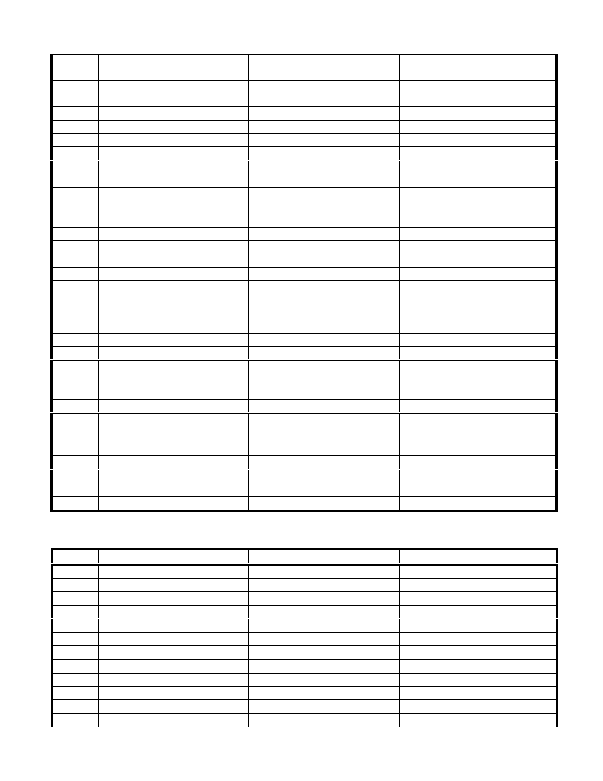
QSC/QSL9 - OEM 50 Pin connector
Pin Pinout Type Signal Name Feature
1 600 mA current sink to ground Stop Lamp Engine Protection/Diagnostics
2 600 mA current sink to ground Water in Fuel Lamp Water-In-Fuel
3 600 mA current sink to ground Diagnostic Lamp Diagnostics
4 600 mA current sink to ground Maintenance Lamp Diagnostics
5 600 mA current sink to ground Dual Output Driver A Dual Outputs
7 <50 ohm Closed, 50Kohm Open CC/ISC Resume Switch Input Cruise Control/ISC Increment
8 Vehicle/Tail Shaft Speed Sensor Vehicle Speed Sensor + Input Vehicle Speed
9 Remote Throttle Sensor Remote Throttle Pedal Position
Input
10 Remote throttle (VsensorB) Remote Throttle +5VDC Remote Throttle
11 600 mA current sink to ground Wait to Start Lamp Intake Air Heater/Grid Heater
12 Frequency Output Tachometer Output (Logic Level) Tachometer
13 Switch (Pulled up) CC/ISC Set /Coast Switch Input Cruise Control/ISC Decrement
14 <50 ohm Closed, 50Kohm Open CC/On-OFF Switch Input Cruise Control
15 Reserved
16 <50 ohm Closed, 50Kohm Open Fan Clutch Switch Input Fan Clutch
17 <50 ohm Closed, 50Kohm Open Boost Power Request Switch Boost Power
18 Vehicle Speed Sensor Vehicle Speed Sensor - Input Vehicle Speed
19 Ground Throttle Return Throttle
20 Ground Remote Throttle Return Remote Throttle
21 3 amps Dedicated PWM Output Dedicated PWM
22 Reserved
23 <50 ohm Closed, 50Kohm Open ISC 3 / ISC Validation Intermediate Speed Control
24 50 ohm Closed, 50Kohm Open Multi-Unit Sync On/Off Switch Multi-Unit Sync
Remote Throttle
Page 21
Page 21 of 38
AEB15.44
25 125 ohm Closed, 50 Mohm Open Off Idle Sw Idle Validation
26 <125 ohm Closed, 50 Mohm
Open
27 <50 ohm Closed, 50Kohm Open Clutch Switch Input Exhaust Brakes
28 <50 ohm Closed, 50Kohm Open ISC 1 Switch Input Intermediate Speed Control
29 +5 Vdc supply V Throttle +5VDC Throttle
30 Throttle Position Sensor Throttle Pos Input Signal Throttle
31 1 amp, Hi side Drive Cold Start Aid Relay 2 Intake Air Heater/Grid Heater
32 Reserved
33 <50 ohm Closed, 50Kohm Open Brake Switch Input Exhaust Brakes
34 <50 ohm Closed, 50Kohm Open Exhaust Brake On/Off Switch
35 <50 ohm Closed, 50Kohm Open Idle/Diag Increment Switch Input Diagnostics, Low Idle Gov.
36 <50 ohm Closed, 50Kohm Open Idle/Diag Decrement Switch Input Diagnostics, Low Idle Gov.
37 <50 ohm Closed, 50Kohm Open Diagnostic On/Off Switch Input Diagnostics
38 <50 ohm Closed, 50Kohm Open Multi-Unit Sync Complementary
39 A/D Input Alternate Torque Derate Switch
40 Water In Fuel Sensor Water In Fuel Water-In-Fuel
41 1 amp, Hi side drive Cold Start Aid Relay 1 Intake Air Heater/Grid Heater
42 Reserved
43 <125 ohm Closed, 50 Mohm
Open
44 <50 ohm Closed, 50Kohm Open Alternate Idle Switch Alternate Idle
45 <50 ohm Closed, 50Kohm Open Remote Throttle On/Off Input Remote Throttle
46 Switch (Pulled up) Aux. Governor On/Off Input Auxiliary Speed Governor
On Idle Sw Idle Validation
Exhaust Brakes
Input
Multi-Unit Sync
Switch
Alternate Torque
Input
AC Pressure Switch Fan Clutch
47 <50 ohm Closed, 50Kohm Open ISC 2 Switch Input Intermediate Speed Control
48 A/D Input OEM Pressure Sensor Input OEM Pressure
49 Datalink J1708/J1587 Datalink + J1587 Datalink
50 Datalink J1708/J1587 Datalink - J1587 Datalink
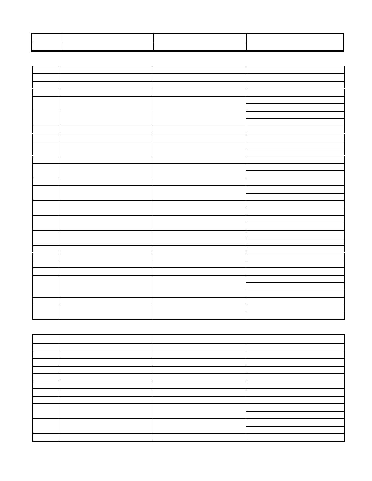
QSM11/QSX15 - OEM 50 Pin connector
Pin Pinout Type Signal Name Feature
1 10V Switched Pullup Input AXG On/Off Switch Auxiliary Speed Governor
2 10V Switched Pullup Input Alternate Torque Switch Switchable Torque
3 IVS 10V Switched Pullup Input Off Idle Switch Base Throttle
Frequency Throttle
4 Switched Sink Driver Output Wait-To-Start Lamp Intake Air Heater
5 Switched Sink Driver Output Maintenance Lamp Real-Time Clock
Water-In-Fuel
Maintenance Monitor
6 Switched Sink Driver Output Stop Lamp Diagnostics
Engine Protection
7 ECM Supply (+) ECM Supply (+) All
8 ECM Supply (+) ECM Supply (+) All
Page 22

Page 22 of 38
AEB15.44
9 ECM Switch Return Panel Return 1 All
10 ECM Switch Return Panel Return 2 All
11 Tachometer Source Driver
Output
12 10V Switched Pullup Input EP Shutdown Override Switch Engine Protection
13 IVS 10V Switched Pullup Input On Idle Switch Base Throttle
14 10V Switched Pullup Input Diagnostics Increment Diagnostics
F MULTIFUNCTION pinout ISC Increment Intermediate Speed Control
15 10V Switched Pullup Input Fan Accessory Switch Electronic Fan Clutch
16 Switched Sink Driver Output Warning Lamp Diagnostics
17 ECM Supply (+) ECM Supply (+) All
18 ECM Supply (+) ECM Supply (+) All
19 ECM Switch Return MUS ID Return Multiple Unit Synchronization
20 ECM Switch Return Remote Return Remote Throttle
21 APS Ratiometric Analog Input Remote Throttle Position Remote Throttle
F RECONFIGURABLE pinout Variable ISC Intermediate Speed Control
22 10V Switched Pullup Input MUS ID1
23 10V Switched Pullup Input ISC Switched Speed 1 Intermediate Speed Control
24 10V Switched Pullup Input Diagnostics Decrement Diagnostics
F MULTIFUNCTION pinout ISC Decrement Intermediate Speed Control
25 10V Switched Pullup Input ISC Switched Speed 2 Intermediate Speed Control
26 J1587 Datalink (+) J1587 Datalink (+) J1708/J1587 Datalink
27 J1587 Datalink (-) J1587 Datalink (-) J1708/J1587 Datalink
28 ECM Supply (+) ECM Supply (+) All
29 ECM Supply Return ECM Supply Return All
30 ECM Supply Return ECM Supply Return All
31 10V Switched Pullup Input MUS ID2
32 10V Switched Pullup Input MUS ID3
Engine Brake Select 3 (QSX15)
33 10V Switched Pullup Input ISC Switched Speed 3 Intermediate Speed Control
F RECONFIGURABLE pinout ISC Validation Intermediate Speed Control
34 10V Switched Pullup Input MUS On/Off Validation Multiple Unit Synchronization
35 Switched Source Driver Output Idle Shutdown Relay Low Idle Shutdown
36 J1939 Datalink Shield J1939 Datalink Shield J1939 Datalink
37 J1939 Datalink (-) J1939 Datalink (-) J1939 Datalink
38 Switched Pulldown Input Keyswitch All
39 ECM Supply Return ECM Supply Return All
40 ECM Supply Return ECM Supply Return All
41 10V Switched Pullup Input Alternate Droop Switch Alternate Droop
42 10V Switched Pullup Input MUS On/Off Switch Multiple Unit Synchronization
43 10V Switched Pullup Input Remote Throttle Switch Remote Throttle
44 10V Switched Pullup Input Diagnostics Enable Diagnostics
F MULTIFUNCTION pinout Manual Snapshot User-Activated Datalogger
45 10V Switched Pullup Input Alternate Low Idle Switch Switchable Low Idle
Tachometer All Tachometer
Frequency Throttle
Idle Increment Low Idle Governor
Low Idle Shutdown
Multiple Unit Synchronization
Engine Brake Select 1
Idle Decrement Low Idle Governor
Multiple Unit Synchronization
Engine Brake Select 2
Multiple Unit Synchronization
Engine Brakes
Engine Brakes
Engine Brakes (QSX15)
Page 23

Page 23 of 38
AEB15.44
46 J1939 Datalink (+) J1939 Datalink (+) All
47 APS Ratiometric Analog Input Base Throttle Position Base Throttle
48 APS 5V Sensor Voltage Source Throttle Supply (+) Base Throttle
Remote Throttle
Intermediate Speed Control
49 ECM Switch Return Throttle Supply Return Base Throttle
Remote Throttle
Intermediate Speed Control
50 ECM Supply Return ECM Supply Return All
QSM11/QSX15 - OEM 31 Pin connector
Pin Pinout Type Signal Name Feature
1 5V Sensor Voltage Source not used none
2 Ratiometric Analog Input not used none
3 ECM Switch Return OEM Temperature Return Switched Outputs
Electronic Fan Clutch
4 Resistive Analog Input OEM Temperature Switched Outputs
Electronic Fan Clutch
5 5V Switched Pullup Input Coolant Detected Engine Protection
6 5V Switched Pullup Input Coolant Not Detected Engine Protection
7 5V Sensor Voltage Source Coolant Level Supply (+) Engine Protection
8 Switched Source Driver Output Switched Output B Switched Outputs
9 Switched Source Driver Output Engine Speed PWM Dedicated Output
F RECONFIGURABLE pinout Engine Torque PWM Dedicated Output
Commanded Throttle PWM Dedicated Output
10 Switched Source Driver Output Intake Air Heater Intake Air Heater
11 ECM Solenoid Return Solenoid Return Switched Outputs
12 Switched Source Driver Output Fan Clutch Electronic Fan Clutch
13 ECM Solenoid Return Fan Clutch Return Electronic Fan Clutch
14 5V Sensor Voltage Source not used none
15 Hall Effect Input not used none
16 ECM Switch Return SE Return various features
17 10V Switched Pullup Input AC Pressure Switch PWM Dedicated Output
18 ECM Switch Return AC Pressure Return Electronic Fan Clutch
19 ECM Switch Return Coolant Level Return Electronic Fan Clutch
20 Switched Sink Driver Output not used none
21 Variable Reluctance Input (+) Shaft Speed (+) Auxiliary Governor
F RECONFIGURABLE pinout Switched Outputs
22 Variable Reluctance Input (-) Shaft Speed (-) Auxiliary Governor
F RECONFIGURABLE pinout Switched Outputs
Frequency Throttle (+) Frequency Throttle
Transmission Synch (+) Transmission Synchronization
23 Resistive Analog Input not used none
24 ECM Switch Return spare as required
25 10V Switched Pullup Input not used none
26 not connected not used none
27 Switched Source Driver Output Switched Output A Switched Outputs
28 ECM Switch Return OEM Switch Return Switched Outputs
29 Switched Source Driver Output not used none
Page 24
Page 24 of 38
AEB15.44
30 5V Switched Pullup Input Alternate Torque Select Alternate Torque
31 5V Switched Pullup Input OEM Switch Switched Outputs
QSK19 – OEM 21 Pin Connector
Pin Pinout Type Signal Name Feature
A Source Driver Output Dual Output A Dual Outputs
C Source Driver Output Dual Output B Dual Outputs
D ECM Supply (+) Unswitched Battery All
F Ratiometric A/D Input OEM Pressure
G ECM Supply (+) Unswitched Battery All
H PWM Source Driver Fan Clutch Electronic Fan Clutch
J Resistive A/D Input OEM Temperature Return
K Ratiometric A/D Input OEM Temperature
Frequency Throttle
Frequency Throttle
Variable ISC Position
Variable ISC Supply
OEM Pressure Sensor Supply
S 5V Switched Pullup Input Coolant Level High Input Engine Protection
T 5V Switched Pullup Input Coolant Level Low Input Engine Protection
V ECM Sensor Return Coolant Level Return
OEM Pressure Sensor Supply
W PWM Output Output Dedicated PWM Output Dedicated PWM
Variable ISC Return
Dual Outputs
Electronic Fan Clutch
Engine Protection
Auxiliary Governor
Dual Outputs
Electronic Fan Clutch
Engine Protection
Dual Outputs
Electronic Fan Clutch
Engine Protection
Auxiliary GovernorL Variable Reluctance Input (+) Auxiliary Shaft Speed
Frequency Throttle
Auxiliary GovernorM Variable Reluctance Input (-) Auxiliary Shaft Speed
Frequency Throttle
Remote ThrottleN APS Ratiometric Analog Input Remote Throttle Position
Variable ISC
Remote ThrottleP APS Sensor 5V Source Voltage Remote Throttle Supply
Variable ISC
Engine ProtectionU 5V Sensor Supply Coolant Level Supply (+)
Engine Protection
Centinel (CORS)
Remote ThrottleX ECM Throttle Return Remote Throttle Return
Variable ISC
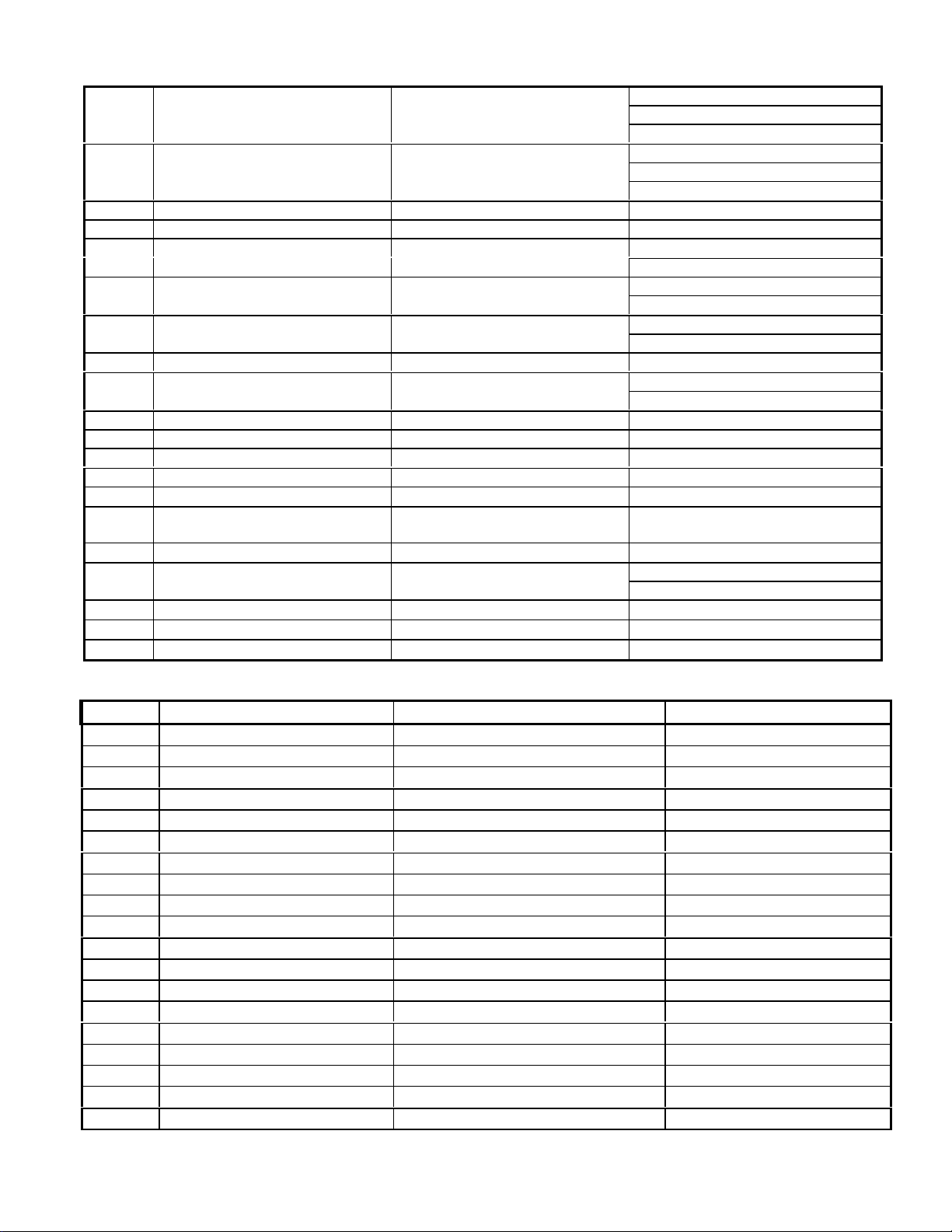
QSK19 – OEM 31 Pin Connector
Pin Pinout Type Signal Name Feature
1 Switched Pulldown Input Vehicle Keyswitch Input Keyswitch
2 J1587 Data Link + J1587 Data Link + J1708/J1587 Datalink
3 J1587 Data Link + J1587 Data Link - J1708/J1587 Datalink
4 APS Sensor 5V Source Voltage Throttle Supply Primary Throttle
5 APS Ratiometric Analog Input Throttle Position Primary Throttle
6 ECM Throttle Return Throttle Return Primary Throttle
7 Switched Pullup Input Idle Validation Off Idle Idle Validation
8 Switched Pullup Input Idle Validation On Idle Idle Validation
Auxiliary Governor9 12V Switched Pullup Input AXG Enable Switch
Alternate Idle Switch
Cold Idle Inhibit
11 12V Switched Pullup Input Multi-Unit Sync On/Off Multi-Unit Synchronization
Switched Alternate Idle
Dual Outputs10 12V Switched Pullup Input OEM Switch
Coolant Temp. Based Alt. Idle
Page 25
Page 25 of 38
AEB15.44
12 12V Switched Pullup Input ISC/Idle Increment
Intermediate Speed Control
13 12V Switched Pullup Input ISC/Idle Decrement
Intermediate Speed Control
14 12V Switched Pullup Input Alternate Torque Switch Alternate Torque
15 12V Switched Pullup Input Alternate Droop Switch Alternate Droop
19 12V Switched Pullup Input ISC 3/ISC Validation Intermediate Speed Control
Intermediate Speed Control20 12V Switched Pullup Input ISC 2/Remote Throttle
21 12V Switched Pullup Input ISC 1 Intermediate Speed Control
22 Tachometer Source Driver Tachometer Output Tachometer
23 12V Switched Pullup Input Remote Oil Level Centinel (CORS)
24 Battery Supply Unswitched Battery Datalink Connector Supply
25 ECM Return Block Ground All
26 Switched Source Driver Output Ether Injection
Centinel Make-Up Valve
27 12V Switched Pullup Input Dashboard Fan Clutch Electronic Fan Clutch
Variable ISC Position
29 5V DC Supply (+) Unused 5V DC Supply (+) N/A
30 ECM Return Block Ground All
31 ECM Switch Return Idle Validation Switch Return Idle Validation
Diagnostics
Low Idle Governor
Diagnostics
Low Idle Governor
Diagnostics16 Switched Sink Driver Output Red Stop Lamp
Engine Protection
Diagnostics17 Switched Sink Driver Output Yellow Warning Lamp
Low Idle Shutdown
Engine Protection18 Switched Sink Driver Output White Maintenance Lamp
Maintenance Monitor
Remote Throttle
Controlled Ether Injection
Remote Throttle28 APS Ratiometric Analog Input Remote Throttle Position
Variable ISC
QST 30 - OEM 21 Pin Connector
Pin Pinout Type Signal Name Feature
A Switched Pullup Input Vehicle Key Switch Input ALL
B Battery Ground -V Battery ALL
C Switched Driver Output Solenoid A Switched Outputs
D Unswitched Battery Supply +V Battery (secondary engine) ALL
E Battery Ground -V Battery (Secondary engine) ALL
F Switched Driver Output Solenoid B Switched Outputs
G Unswitched Battery Supply -V Battery ALL
H Data Bus J 1587 Data Link + (primary engine) J1587 Datalink
J Data Bus J 1587 Data Link - (primary engine) J1587 Datalink
K Output Remote Throttle Supply Remote Throttle
L Analog Input Remote Throttle Position Input Signal Remote Throttle
M Input Remote Throttle Return Remote Throttle
N Switched Pulldown Input Remote Idle Validation 1 On Idle Validation
P Switched Pulldown Input Remote Idle Validation 2 Off Idle Validation
R Output Throttle Supply Primary Throttle
S Analog Input Throttle Position Input Signal Primary Throttle
T Input Throttle Return Primary Throttle
U Switched Pulldown Input Idle Validation 1 On Idle Validation
V Switched Pulldown Input Idle Validation 2 Off Idle Validation
Page 26

Page 26 of 38
AEB15.44
W Data Bus J1587 Data Link + (secondary engine) J1587 Datalink
X Data Bus J 1587 Data Link - (secondary engine) J1587 Datalink
QST30 - OEM 31 Pin Connector
Pins Pinout Type Signal Name Feature
1 Analog Input Frequency Throttle Input Frequency Throttle
2 Switched Pulldown Input Fan Clutch Switch Fan Clutch
3 Analog Output Coolant Temperature Gauge Coolant Temp Gauge
4 PWM Source Driver Output PWM Torque Broadcast Output Dedicated PWM
5 Analog Output Oil Pressure Gauge Oil Pressure Gauge
6 Switched Source Driver Output Tachometer Output Signal Tachometer Output
7 Switched Sink Driver Output Lamp 4 / Wait To Start Grid Heater
8 Switched Pulldown Input Coolant Level High Input Signal Coolant Level
9 Switched Pulldown Input Coolant Level Low Input Signal Coolant Level
10 Switched Sink Driver Output Lamp 5 / Spare Lamp #1 Diagnostics
11 Switched Sink Driver Output Lamp 6 / Spare Lamp #2 Diagnostics
12 Switched Sink Driver Output Lamp 1 / Stop Diagnostics
13 Switched Sink Driver Output Lamp 2 / Diagnostics Diagnostics
14 Switched Sink Driver Output Lamp 3 / Engine Protection Diagnostics
15 Switched Pulldown Input Diagnostic On/Off Diagnostics
16 Switched Pulldown Input Torque Curve Select Alternate Torque
17 Switched Pulldown Input Hi Speed Gov. Droop Select Alternate Droop
18 Switched Pulldown Input Alternate Idle Switch Input Alternate Idle
19 Switched Pulldown Input Idle and Diagnostic Increment Diagnostics & Low Idle
20 Output Coolant Level Supply Coolant Level
21 Input Coolant Level Return Coolant Level
22 Switched Pulldown Input Idle and Diagnostic Decrement Diagnostics & Low Idle
23 Switched Pulldown Input PTO 1 Intermediate Speed Control
24 Switched Pulldown Input PTO 2 / Remote Throttle Select Intermediate Speed
Control/Remote Throttle
25 Switched Pulldown Input PTO Validate Intermediate Speed Control
26 Switched Pulldown Input Clutch Switch Clutch Input
27 Switched Pulldown Input PTO Increment Intermediate Speed Control
28 Switched Pulldown Input PTO Decrement Intermediate Speed Control
29 Switched Pulldown Input PTO On/Off Intermediate Speed Control
30 Switched Pulldown Input Service Brake Service Brakes
31 Switched Pulldown Input Droop Switch Input High Speed Governor Droop
Section VIII – Pinout Specifications
Disclaimer: The pinout specification is applicable to the QSM11/QSX15 circuit requirements and
descriptions may be different for each engine platform.
Page 27
Page 27 of 38
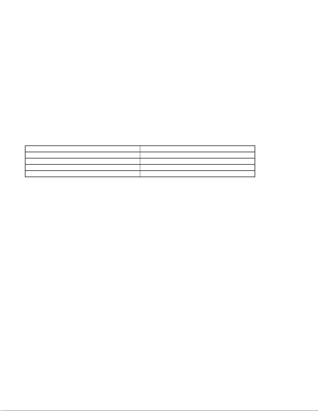
* Note - the differences will be added in future revisions to this document
5V Sensor Voltage Source Pinout Specifications/APS 5V Sensor Voltage Source Pinout
Specifications
Application. There are two 5V ECM regulated power supplies available to the OEM. The primary supply is
available at any 5V Sensor Voltage Source pinout. This supply is used as excitation voltage for ratiometric
sensors such as pressure sensors. There is also an electrically independent 5V supply available at the APS 5V
Sensor Voltage Source pinout. It is designed to provide excitation voltage for Accelerator Position Sensors
(APS’s).
Note: Specifications for the APS 5V Sensor Voltage Source Pinout are defined in CES 14118 except as
noted.
5V Sensor Voltage Source Pinout Specifications
Item Requirement
Pin Voltage 5V ±5%
Maximum Current Per Pin 50 mA, 10 mA APS
Maximum Total Current (Sum of All Pins) 200 mA, 10 mA APS
Maximum Ripple Voltage 100 mV p-p
AEB15.44
5V Switched Pullup Input Pinout Specifications
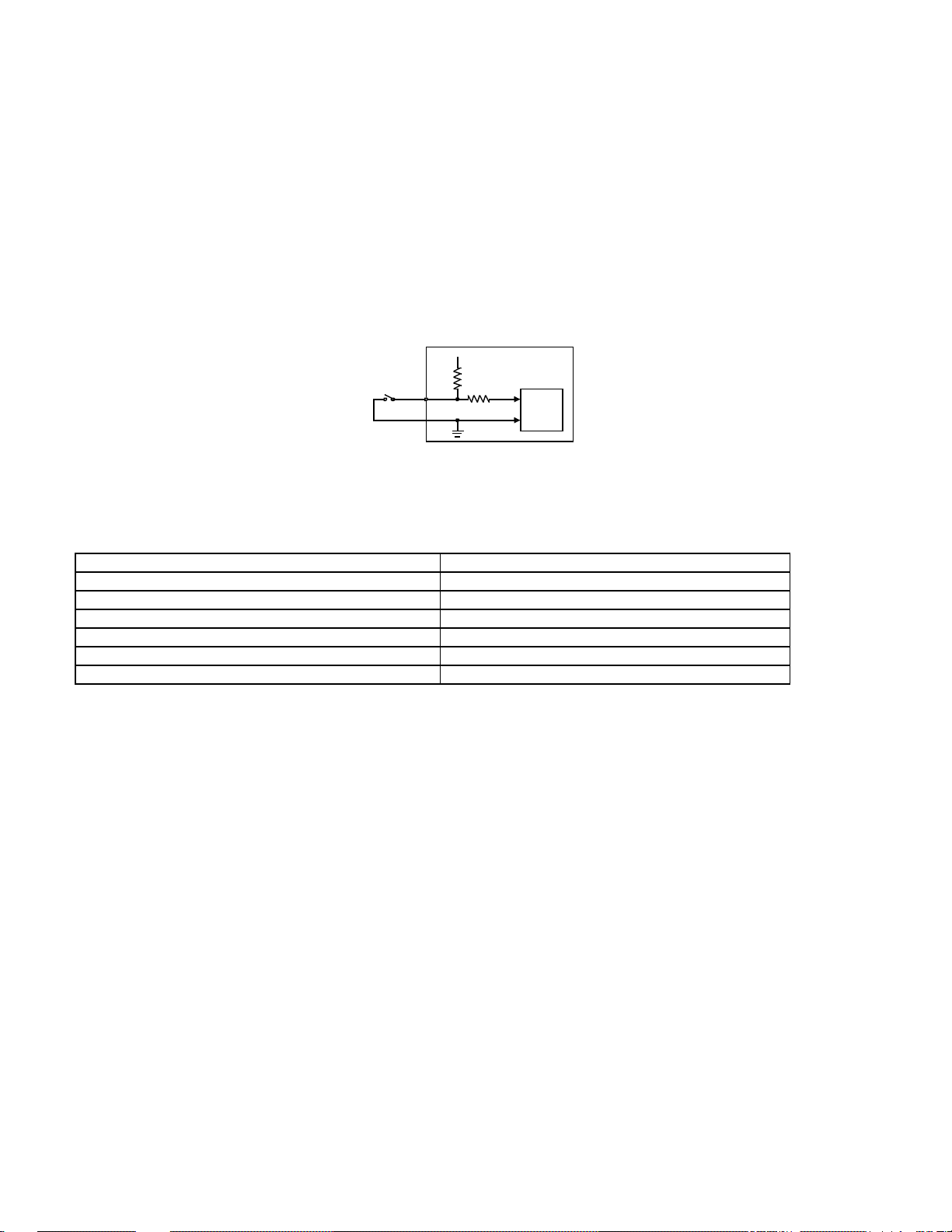
Application. The 5V Switched Pullup Input pinout type detects the state of a low-voltage, OEM-supplied binary
switch or switching device. A typical application is the coolant level switch. The pinout is connected to one contact
of the OEM switch. ECM ground is connected to the other contact of the OEM switch.
Page 28
Page 28 of 38
AEB15.44
Note. For proper operation, the OEM switch must always be returned to ECM ground as defined in the
Installation Recommendations section and IS-1377-9802.
Operation. The 5V Switched Pullup Input pinout can exist is one of two states: Grounded (@ 0 volts) or Not
Grounded (@ 5 volts). These states are dictated by OEM switch position as follows.
a. Grounded State . When the OEM switch is closed, Nominal Pinout Current is present through the
pinout by way of the 470 Ohm pullup resistor. Grounded Source Resistance can be measured between
the pinout and ECM ground. Grounded Pin Voltage can be measured at the pinout with respect to ECM
ground. The microprocessor detects a logic level low.
b. Not Grounded State . When the OEM switch is opened, Pinout Current is minimal. Not Grounded
Source Resistance can be measured between the pinout and ECM ground. Not Grounded Pin Voltage
can be measured at the pinout with respect to ECM ground. The microprocessor detects a logic level high
Electronic Control Module
+5V
OEM
Switch
Pinout
5V Switched Pullup Input Pinout Simplified Circuit
470
47K
Micro
5V Switched Pullup Input Pinout Specifications
Item Requirement
Number of States Two: GROUNDED or NOT GROUNDED
Nominal Pinout Current 10 mA
Maximum Grounded Pin Voltage 1.5 V
Minimum Not Grounded Pin Voltage 4 V
Maximum Grounded Source Resistance 125 Ohm
Minimum Not Grounded Source Resistance 50k Ohm
10V Switched Pullup Input Pinout Specifications/IVS 10V Switched Pullup Input Pinout
Specifications
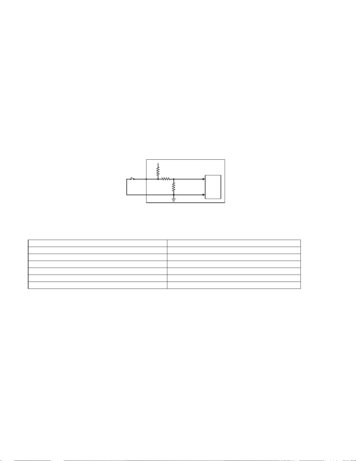
Application. The 10V Switched Pullup Input pinout type detects the state of an OEM-supplied binary mechanical
or solid-state switch. Typical applications are panel-mounted toggle switches and Idle Validation Switches (IVS’s).
The pinout is connected to one contact of the OEM switch. ECM ground is connected to the other contact of the
Page 29
Page 29 of 38
AEB15.44
OEM switch. There are two 10V Switched Pullup Input pinouts designated IVS which are similar in operation to,
but elec trically independent from, non-IVS pinouts.
Note. For proper operation, the OEM switch must always be returned to ECM ground as defined in the
Installation Recommendations section and IS-1377-9802. Specifications for the IVS 10V switched Pullup
Input pinout are defined in CES 14118 except as noted.
Operation. The 10V Switched Pullup Input pinout can exist in one of two states: Grounded (@ 0 volts) or Not
Grounded (@ 10 volts). These states are dictated by OEM switch position as follows.
a. Grounded State . When the OEM switch is closed, Nominal Pinout Current is present through the
pinout by way of the 1K pullup resistor. Grounded Source Resistance can be measured between the
pinout and ECM ground. Grounded Pin Voltage can be measured at the pinout with respect to ECM
ground. The microprocessor detects a logic level low.
b. Not Grounded State . When the OEM switch is opened, Pinout Current is minimal. Not Grounded
Source Resistance can be measured between the pinout and ECM ground. Not Grounded Pin Voltage
can be measured at the pinout with respect to ECM ground. The microprocessor detects a logic level
high.
Electronic Control Module
+10V
OEM
Switch
Pinout
1K
47K
62K
100K IVS
Micro
10V Switched Pullup Input Pinout Simplified Circuit
10V Switched Pullup Input Pinout Specifications
Item Requirement
Number of States Two: GROUNDED or NOT GROUNDED
Nominal Pinout Current 10 mA
Maximum Grounded Pin Voltage 2 V, 1.5 V IVS
Minimum Not Grounded Pin Voltage 8 V, 5.5 V IVS
Maximum Grounded Source Resistance 100 Ohm, 125 Ohm IVS
Minimum Not Grounded Source Resistance 50k Ohm
ECM Supply (+) Pinout Specifications/ECM Supply Return Pinout Specifications
Application. There are five ECM Supply (+) pinouts and five ECM Supply Return pinouts. These pinouts supply
primary CM570 subsystem operating power to the ECM.
Note. This is a critical interface, special connection requirements must be followed as defined in the
Installation Recommendations section and IS-1377-9807.
Page 30

Page 30 of 38
ECM Supply Pinout Specifications
Item Requirement
Supply Voltage 9-32 Vdc
Maximum Key-On Current 25A @ 12V, 15A @ 24V
Maximum Key-Off Current (Dormant Mode) 40 mA @ 12V, 80 mA @ 24V
Maximum Circuit Resistance, ECM to battery (+
and -)
40mOhms
ECM Switch Return Pinout Specifications
Application. There are two types of ECM returns available to the OEM. These returns are available at several
ECM pinouts. The ECM Switch Return pinouts provide a return for switches or sensors. The ECM Solenoid
Return pinouts provide a return for relay coils or solenoids.
Note. For proper operation, special installation requirements must be followed as defined in the
Installation Recommendations section and IS-1377-9807.
AEB15.44
ECM Return Pinout Specifications
Item Requirement
Maximum Current Per Pin 7.5A*
Maximum Total Current (Sum of all Pins) 12.5A
* The following pinouts are limited to 5 A: Frequency Return and OEM Switch return
Ratiometric Analog Input Pinout Specifications/APS Ratiometric Analog Input Pinout
Specifications
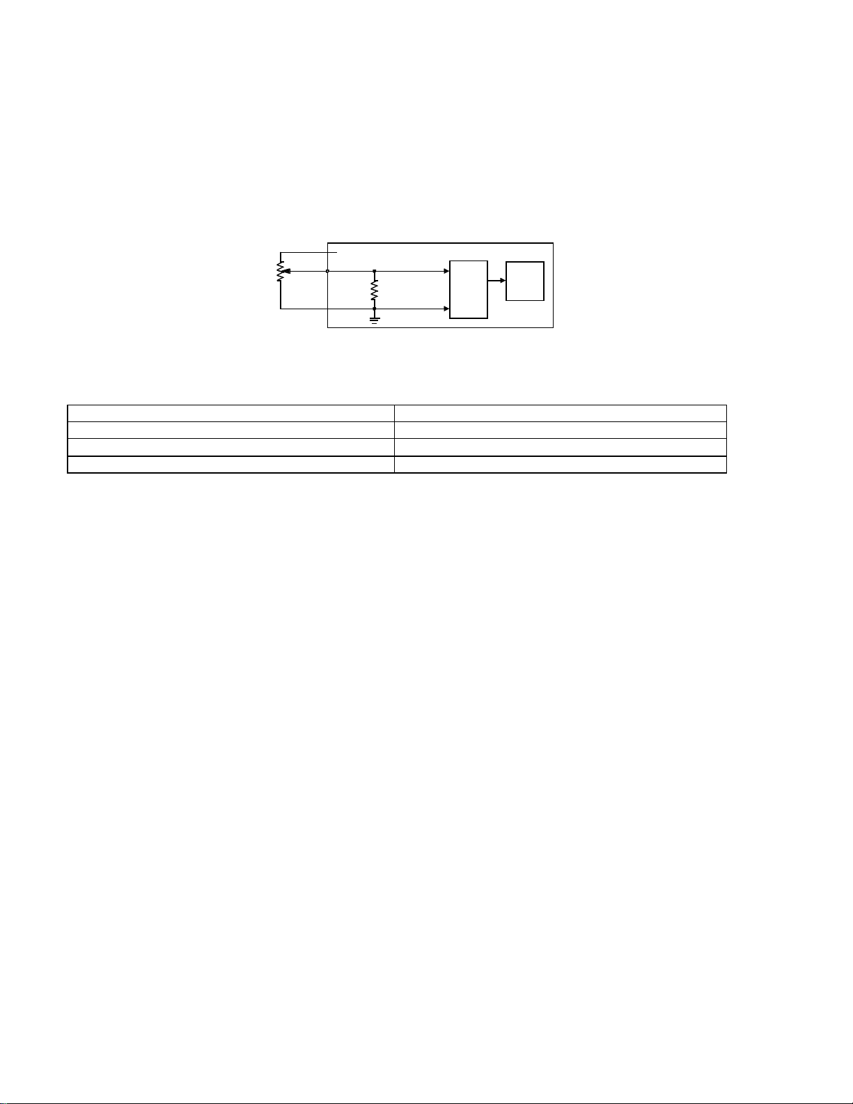
Application. The Ratiometric Analog Input pinout detects the signal from an OEM-supplied ratiometric sensor.
Ratiometric sensors are three-wire sensors that provide a continuously variable output voltage that represents a
measured analog parameter. Typical applications are pressure sensors and Accelerator Position Sensors
(APS’s). The pinout is connected to the center tap of the ratiometric sensor. This sensor is typically connected to
an excitation voltage and ECM ground. There are two Ratiometric Analog Input pinouts designated APS which
are similar in operation to, but electrically independent from, non-APS pinouts.
Page 31
Page 31 of 38
AEB15.44
Note. For proper operation, the ratiometric sensor must always be returned via a dedicated ECM ground
as defined in the Installation Recommendations section. Specifications for the APS Ratiometric Analog
Input pinout are defined in CES 14118 except as noted.
Operation. Current flow is present through the ratiometric sensor, whenever the ECM is powered up, by way of
the +5V source. This results in a voltage drop at the center tap of the ratiometric sensor, which is applied to the
ratiometric Analog Input pinout. Pinout Current is present through the pinout by way of the pulldown resistor.
Pinout Voltage can be measured at pinout with respect to ECM ground. This voltage is sampled by the A/D
converter and supplied to the microprocessor.
+5V
Ratiometric
Sensor
Item Requirement
Resolution 5 mV
Maximum Pinout Current
Maximum Pinout Voltage 5V
Pinout
47K
10K APS
Ratiometric Analog Input Pinout Simplified Circuit
A/D
Micro
Ratiometric Analog Input Pinout Specifications
100 µA, 500 µA APS
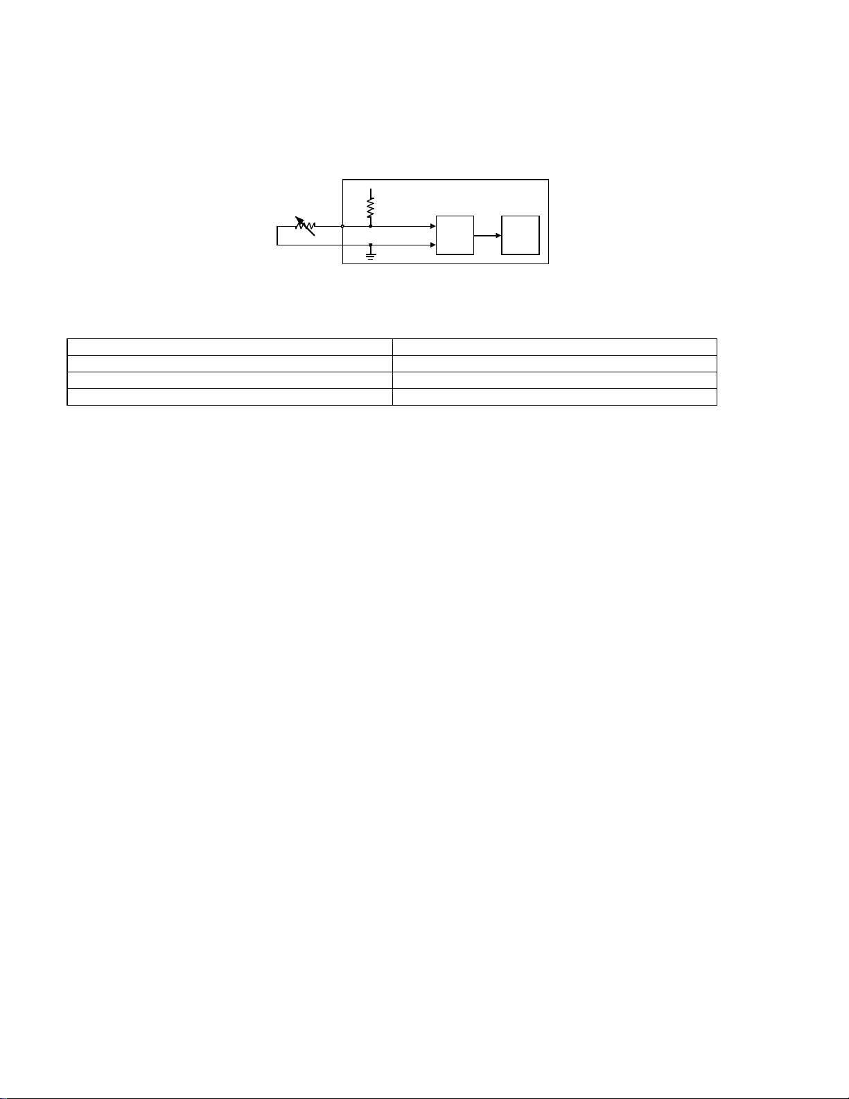
Resistive Analog Input Pinout Specifications/WIF Resistive Analog Input Pinout Specifications
Application. The Resistive Analog Input pinout detects the signal from an OEM-supplied resistive sensor.
Resistive sensors are two-wire sensors that provides a continuously variable resistance that represents a
measured analog parameter. Typical applications are temperature sensors. The pinout is connected to one side
of the OEM sensor. ECM ground is connected to the other side of the OEM sensor. There is a Resistive Analog
Input pinout designated WIF which provides a lower current draw. Its applications are limited to Water-In-Fuel
(WIF) sensors.
Note. For proper operation, the resistive sensor must always be returned via a dedicated ECM ground as
defined in the Installation Recommendations section.
Page 32
Page 32 of 38
AEB15.44
Operation. Pinout Current is present through the Resistive Analog Input pinout, whenever the ECM is powered
up, by way of the pullup resistor. This results in a voltage drop between the pullup resistor and the sensor. Pinout
Voltage can be measured at the pinout with respect to ECM ground. This voltage is sampled by the A/D converter
and supplied to the microprocessor.
Electronic Control Module
+5V
Resistive
Sensor
Pinout
Resistive Analog Input Pinout Simplified Circuit
Resistive Analog Input Pinout Specifications
Item Requirement
Resolution 5 mV
Maximum Pinout Current 1.7 mA, 0.9 mA WIF
No-Load Pinout Voltage 5 V
2.87K
5.62K WIF
MicroA/D
Switched Pulldown Input Pinout Specifications
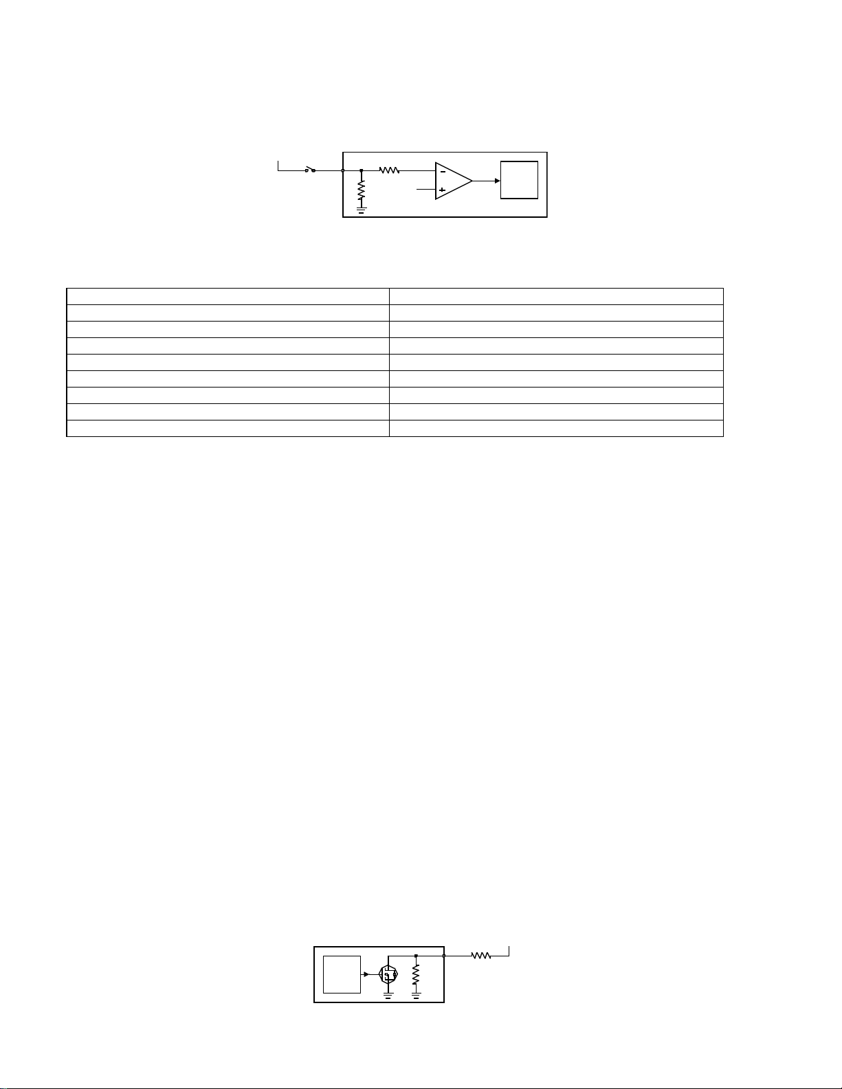
Application. The Switched Pulldown Input pinout detects the critical Keyswitch signal. This signal must be
present in order for the engine to operate. Proper connection of the Keyswitch signal is critical to proper operation
of the CM570 electronic subsystem.
Note. This is a critical interface; special connection requirements must be followed as defined in the
Installation Recommendations section and IS-1377-9807.
Operation. The Switched Pulldown Input pinout can exist in one of two states: Key-On (@ Vbatt+) or Key-Off (@
0 volts). Pinout state is dictated by keyswitch position as follows.
a. Key-On. When the keyswitch is closed, Nominal Pinout Current is present through the pinout by way of
the 1K pulldown resistor. Key-On Source Voltage can be measured at the pinout with respect to ECM
ground. This voltage is greater than a reference voltage and turns an op amp OFF. After the op amp has
been OFF for the Key-On Time, the micro assumes the Key-On state.
Page 33
Page 33 of 38
OEM V+
b. Key-Off. When the keyswitch is opened, Pinout Current is minimal. Key-Off Source Voltage can be
measured at the pinout with respect to ECM ground. This voltage is less than a reference voltage and
turns the op amp ON. After the op amp has been ON for the Key-Off Time, the micro assumes the KeyOff state.
KeyswitchVbatt+
Switched Pulldown Input Pinout Simplified Circuit
Electronic Control Module
Pinout
1K
Vref
Micro
Switched Pulldown Input Pinout Specifications
Item Requirement
Number of States Two: KEY ON or KEY OFF
Nominal Pinout Current 12 mA @ 12V, 24 mA @ 24V
Maximum Key-On Source Voltage 32 V
Minimum Key-On Source Voltage 6.0 V
Maximum Key-Off Source Voltage 4.0 V
Minimum Key-On Time 50 msec
Minimum Key-Off Time 150 msec
Maximum Allowable Key-On Drop-Out Time 80 msec
AEB15.44
Switched Sink Driver Output Pinout Specifications
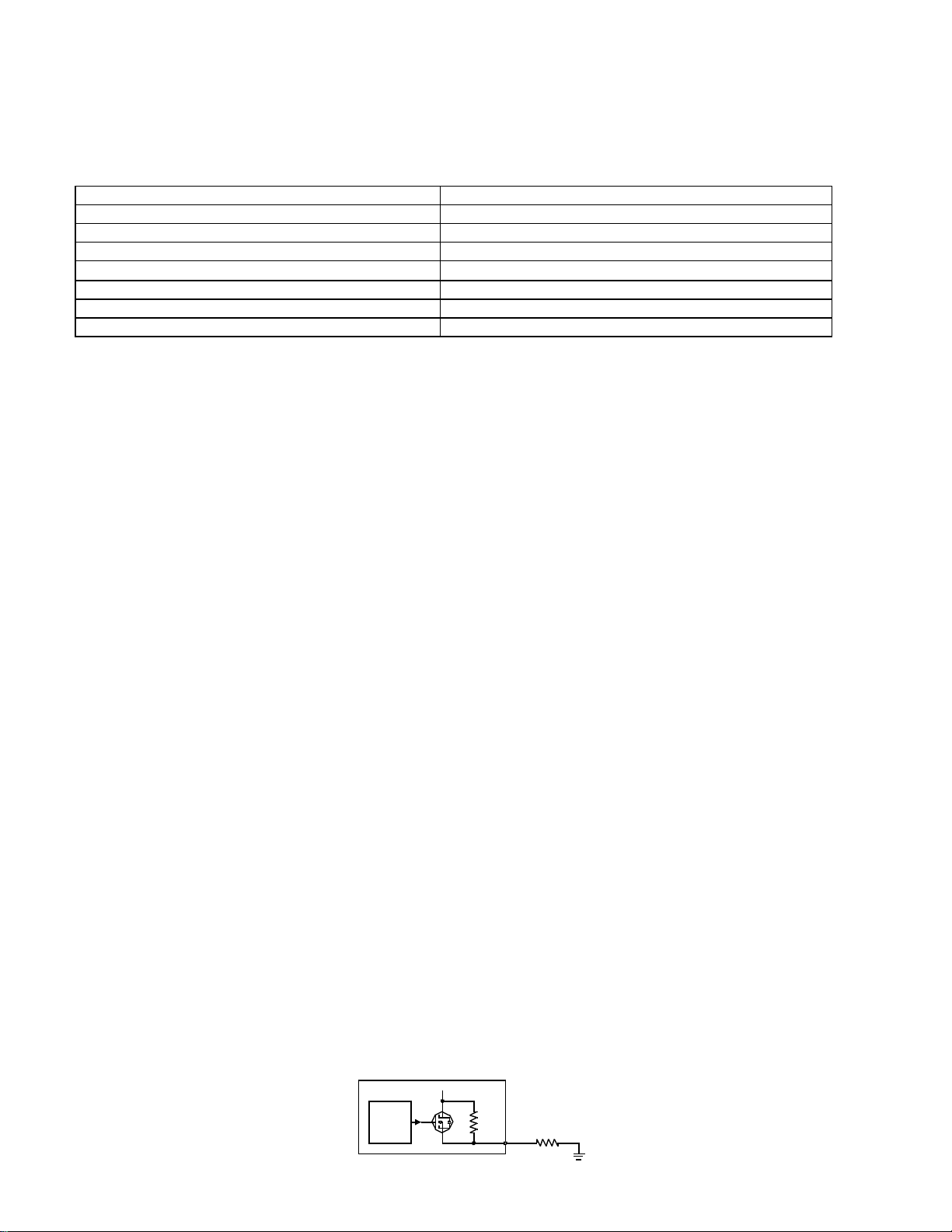
Application. The Switched Sink Driver Output pinout type sinks an OEM-supplied load. The only applications are
dashboard lamps. The pinout is connected to one side of the OEM load. A voltage source, typically Vbatt+, is connected to the other side of the OEM load.
Operation. The Switched Sink Driver Output pinout can exist in one of two states: Sink (low impedance) or Off
(high impedance). These states are dictated by a microprocessor-controlled FET switch as follows.
a. Sink State . Pinout Voltage can be measured at the pinout with respect to ECM ground. When the FET
switch is opened, Pinout Current is present through the pinout by way of the FET switch. Load Resistance
can be measured between the pinout and the OEM voltage source. The OEM load is on or energized.
b. Off State . When the FET switch is closed, some leakage Pinout Current is still present by way of the
47K resistor. The OEM load is off or de-energized.
Electronic Control Module
Micro
OEM Load
Pinout
47K
Page 34
Page 34 of 38
Switched Sink Driver Output Pinout Simplified Circuit
Switched Sink Driver Output Pinout Specifications
Item Requirement
Number of States Two: SINK or OFF
Maximum Pinout Voltage 32V
Maximum Pinout Current (Non-Inductive Load) 600 mA
Minimum Load Resistance
20 Οhm @ 12V, 40 Ohm @ 24V
Maximum Peak Current (Non-Inductive Load) 6.0 A for 20 msec
Maximum Pinout Current (Inductive Load) 2.5 A @ 12V, 1 A @ 24V
Maximum Load Induction 40 mH @ 12V, 130 mH @ 24V
AEB15.44
Switched Source Driver Output Pinout Specifications
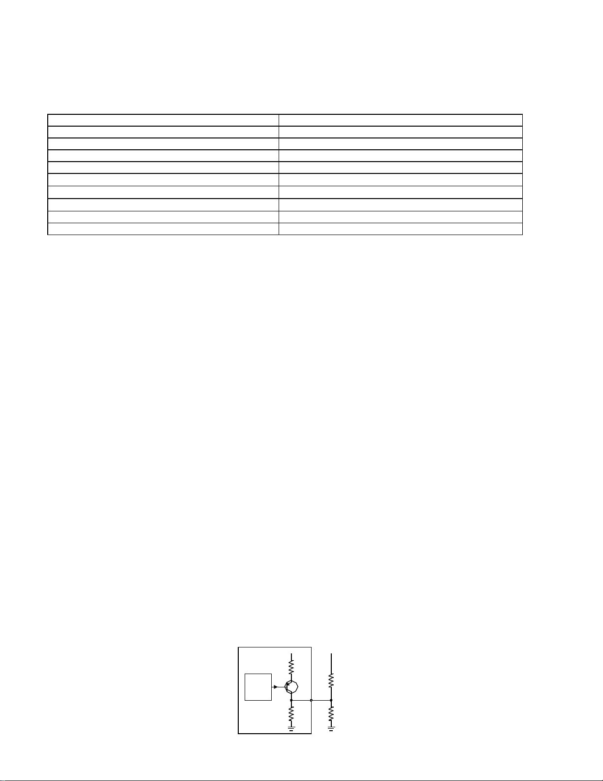
Application. The Switched Source Driver Output pinout type drives a bi-state or PWM OEM-supplied load.
Typical applications are fan clutches or relays. The pinout is connected to one side of the OEM load. A good
chassis ground is connected to the other side of the OEM load. An ECM Solenoid Return pinout may be used as
ground if desired.
Operation. The Switched Source Driver Output pinout can exist in one of two states: Source (@ Vbatt+) or Off
(@ 0 volts). These states are dictated by a microprocessor-controlled FET switch as follows.
a. Source State. When the FET switch is opened, Pinout Current is present through the pinout by way of
the FET switch. Load Resistance can be measured between the pinout and ECM ground. Nominal Pinout
Voltage can be measured at the pinout with respect to ECM ground. The OEM load is on or energized.
b. Off State . When the FET switch is closed, some leakage Pinout Current is still present through the
pinout by way of the 47K resistor. Nominal Pinout Voltage can still be measured at the pinout with respect
to ECM ground. The OEM load is off or de-energized.
Electronic Control Module
Micro
Vbatt+
47K
Pinout
OEM Load
Page 35
Page 35 of 38
OEM Pullup
Switched Source Driver Output Pinout Simplified Circuit
Switched Source Driver Output Pinout Specifications
Item Requirement
Number of States Two: SOURCE or OFF
Number of Modes Two: 2-STATE or PWM
Nominal Pinout Voltage (Vbatt+) - 0.5 volts
Maximum Pinout Current 2 A
Minimum Load Resistance
Maximum Load Resistance (non-inductive load)
Maximum Load Capacitance (non-inductive load)
6 Ohm @ 12V, 12 Ohm @ 24V
2.2 ΚOhm
.01 µF
Frequency Range (PWM) 61-3907 Hz
Maximum Load Induction 130 mH
AEB15.44
Tachometer Source Driver Output Pinout Specifications
Application. The Tachometer Source Driver Output pinout type drives a low-current non-inductive OEM-supplied
load. This pinout may be used to drive a tachometer with a single-ended pulse stream based on engine RPM.
Tachometer requirements are defined ATA/TMC RP-123 except as noted below and in the Signal Descriptions
section.
Operation. The Tachometer Source Driver Output pinout has two states, Source (@ Vbatt+) or Sink (@ 0 volts).
These states are dictated by the microprocessor-controlled transistor switch as follows.
a. Source State. When the transistor switch is opened, forward current flow at the value of Source
Current is present through the pinout by way of the transistor and the 113 Ohm pullup resistor. Load
Resistance can be measured between the pinout and ECM ground. Nominal Source Voltage can be
measured at the pinout with respect to ECM ground.
b. Sink State . For some applications, Sink Voltage can be measured at the pinout with respect to ECM
ground. When the transistor switch is closed, reverse current flow at the value of Sink Current is present
through the pinout by way of the 7.5K pulldown resistor
Electronic Control Module
.
Micro
Vbatt+
113
7.5K
OEM V+
Pinout
OEM Load
Page 36
Page 36 of 38
Tachometer Source Driver Output Pinout Simplified Circuit
Tachometer Source Driver Output Pinout Specifications
Item Requirement
Number of States Two: SOURCE or SINK
Number of Modes One: PWM
Nominal Source Voltage (Vbatt+) - 0.5 volts
Maximum Source Current 100 mA
Minimum Load Resistance 500 Ohm
Maximum Sink Voltage 500 mV
Maximum Sink Current
50 µA
Frequency Range 2-2000 Hz
AEB15.44
Variable Reluctance Input Pinout Specifications - Differential Input
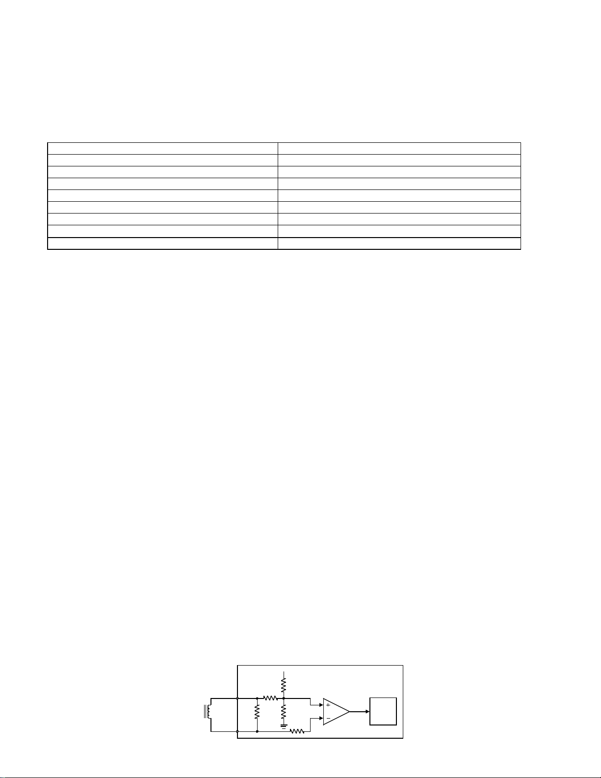
Application. The Variable Reluctance Input pinout detects the frequency of a periodic waveform. The pinout can
operate in one of two configurations: differential or single-ended. A differential input is supplied by a Magnetic
Pickup-type shaft speed sensor. This sensor’s waveform will be an approximately sinusoidal AC voltage. This
input is supplied by two wires, with one wire designated as signal (+) which is referenced to signal (-). These wires
are usually connected directly to the (+) and (-) inputs of the Variable Reluctance Input pinouts.
Note. Specifications for the Variable Reluctance Input pinout are defined in the Installation Recommendations section and IS-1377-9803 except as noted.
Operation. The Variable Reluctance Input pinout can exist in one of two states: High or Low. The states are
dictated by input voltage as follows.
a. High. Source Voltage can be measured at the (+) pinout with respect to the (-) pinout. Current flow is
from the (+) pinout to the (-) pinout by way of the 10K load resistor. Source voltage is positive and turns
an op amp ON.
b. Low . Current flow is from the (-) pinout to the (+) pinout by way of the 10K load resistor. Source
voltage is negative and turns the op amp OFF. The microprocessor monitors op amp state and uses this
information to calculate the signal’s frequency.
Electronic Control Module
(+) Pinout
Source
10K
10K
+5V
1K
1K
Micro
(-) Pinout
Page 37
Page 37 of 38
AEB15.44
Variable Reluctance Input Pinout Simplified Circuit - Differential Input
Variable Reluctance Input Pinout Specifications - Differential Input
Item Requirement
Maximum Source Voltage 26 V rms
Minimum Source Voltage ±0.4 Vrms @ 2 Hz
±0.6 Vrms @ 200 Hz
±4.0 Vrms @ 2 kHz
±8.0 Vrms @ 4 kHz
Maximum Noise Voltage ±0.1 Vrms
Frequency Range 2-8500 Hz
Variable Reluctance Input Pinout Specifications - Single-Ended Input
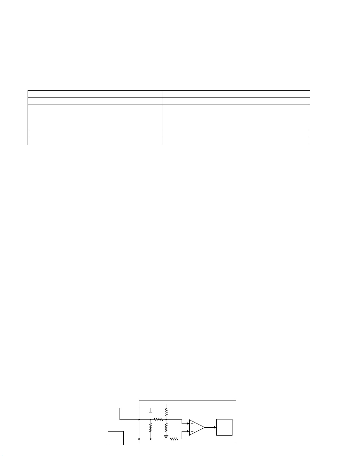
Application. The Variable Reluctance Input pinout detects the frequency of a periodic waveform. The pinout can
operate in one of two configurations: differential or single-ended. A single-ended input is supplied by a pulse
generator source such as a Frequency Throttle. This circuit’s output waveform will be a positive-going pulse
stream with a constant duty cycle and a variable frequency. This signal is usually connected directly to the (-)
input of the Variable Reluctance Input pinouts. The (+) input may be connected to an ECM Switch Return or
allowed to float (grounding is recommended).
Note. Specifications for the Variable Reluctance Input pinout are defined in the Installation Recommendations section and IS-1377-9803 except as noted. The pulse generator source must be properly grounded
as defined in the Installation Recommendations section and the Wiring Diagram section.
Operation. The Variable Reluctance Input pinout can exist in one of two states: High or Low. Pinout state is
dictated by pinout voltage as follows.
a. High. High State Pinout Voltage can be measured at the (-) pinout with respect to ECM ground. This
voltage is greater than a reference voltage and turns the op amp OFF.
b. Low . Low State Pinout Voltage can be measured at the (-) pinout with respect to ECM ground. This
voltage is less than a reference voltage and turns the op amp ON. The microprocessor monitors op-amp
state and uses this information to calculate the signal’s frequency.
Electronic Control Module
(+) Pinout
10K
10K
+5V
1K
1K
Micro
Source
(-) Pinout
Page 38

Page 38 of 38
Variable Reluctance Input Pinout Simplified Circuit - Single-Ended Input
Variable Reluctance Input Pinout Specifications - Single-Ended Input
Item Requirement
Number of States Two: HIGH or LOW
Maximum High State Pinout Voltage 32 V
Maximum Low State Pinout Voltage 0.9 V
Minimum High State Pinout Voltage 4.2 V
AEB15.44
 Loading...