

Page 1

1WMPD4003471
Digital Platform Scale
HV-15KC HV-15KCP
HV-60KC HV-60KCP
HV-200KC HV-200KCP
HW-10KC HW-10KCP
HW-60KC HW-60KCP
HW-100KC HW-100KCP
HW-200KC HW-200KCP
Page 2

© 2017 A&D Company Ltd. All rights reserved.
No part of this publication may be reproduced, transmitted, transcribed, or translated into any language in
any form by any means without the written permission of A&D Company Ltd.
The contents of this manual and the specifications of the instrument covered by this manual are subject
to change for improvement without notice.
Windows, Word and Excel are registered trademarks of the Microsoft Corporation.
Page 3

Contents
1. COMPLIANCE ...............................................................................................................3
1.1. Compliance with FCC rules ........................................................................................3
2. OUTLINE AND FEATURES...........................................................................................4
3. PRECAUTIONS.............................................................................................................5
3.1. Installing the Scale......................................................................................................5
3.2. Operating the Scale ....................................................................................................5
3.3. Storing the Scale.........................................................................................................5
4. INSTALLING THE SCALE .............................................................................................6
4.1. Setting up the Scale....................................................................................................6
4.1.1. Procedure .............................................................................................................6
5. UNPACKING .................................................................................................................7
5.1. Accessories and Options List......................................................................................8
5.2. Installing the Batteries for Type C.............................................................................10
5.3. Removing the Pole....................................................................................................11
5.3.1. Procedure ...........................................................................................................11
5.4. Grounding the scale..................................................................................................12
6. DESCRIPTION OF EACH PART.................................................................................13
6.1. Display and Symbols ................................................................................................14
6.2. Keys..........................................................................................................................16
7. BASIC OPERATION....................................................................................................18
7.1. Turning the Scale on/off and Weighing.....................................................................18
7.1.1. When Using the AC Adapter...............................................................................18
7.1.2. Type C with Batteries..........................................................................................19
7.2. Tare (And Net Display) .............................................................................................20
7.2.1. Tare Input by Weighing.......................................................................................20
7.2.2. Digital Input (Preset Tare)...................................................................................20
7.3. Switchimg the mode..................................................................................................21
8. COUNTING MODE......................................................................................................22
8.1. Storing a Unit Mass...................................................................................................22
8.2. Counting the Number of Articles ...............................................................................23
9. ACCUMULATION FUNCTION.....................................................................................24
10. COMPARATOR ........................................................................................................26
10.1. The formula to compare......................................................................................27
HV/HW-C/CP Series Page 1
Page 4

10.2. Entering the comparator values .............................................................................27
11. AUTO-TARE .............................................................................................................29
11.1. Built-in Printer for HV/HW-CP Series ..................................................................30
12. ID NUMBER AND GLP .............................................................................................32
12.1. Setting the ID number......................................................................................32
12.2. Setting the clock.....................................................................................................33
12.3. GMP report ............................................................................................................34
13. CALIBRATION (ADJUSTING THE SCALE) .............................................................38
13.1. Gravity Acceleration Table..................................................................................39
13.2. Complete Calibration Procedure.........................................................................40
13.2.1. Gravity Acceleration Correction .......................................................................40
13.2.2. Preparation ......................................................................................................40
13.2.3. Calibration of the Zero Point ...........................................................................41
13.2.4. Span Calibration ..............................................................................................41
14. FUNCTION TABLE ...................................................................................................42
14.1. Parameter Setting Procedure.............................................................................42
14.2. Parameter List.....................................................................................................43
15. OPTIONS.................................................................................................................48
15.1. Installing an option..............................................................................................48
15.2. HVW-02CB USB Interface................................................................................48
15.3. HVW-03C RS-232C Interface..............................................................................49
15.4. HVW-04C Comparator Relay Output / Buzzer / Contact Input ............................50
15.5. Communication format...........................................................................................51
15.5.1. Command mode ..............................................................................................52
15.6. Using UFC (Universal Flex Coms) Function .......................................................58
16. SPECIFICATIONS....................................................................................................61
17. MAINTENANCE........................................................................................................65
17.1. Check Points Before Calling Maintenance Service.............................................65
17.1.1. Repair ..............................................................................................................65
Page 2 HV/HW-C/CP Series
Page 5

1. Compliance
1.1. Compliance with FCC rules
Please note that this equipment generates, uses and can radiate radio frequency
energy. This equipment has been tested and has been found to comply with the limits
of a Class A computing device pursuant to Subpart J of Part 15 of FCC rules. These
rules are designed to provide reasonable protection against interference when this
equipment is operated in a commercial environment. If this unit is operated in a
residential area it might cause some interference and under these circumstances the
user would be required to take, at his own expense, whatever measures are
necessary to eliminate the interference.
(FCC = Federal Communications Commission in the U.S.A.)
HV/HW-C/CP Series Page 3
Page 6
2. Outline and Features
The HV-C/HW-C series are platform scales with 1/3000 resolution, and have the triple
weighing range function to select the weighing range. The scale automatically
switches to small scale interval when a light sample is weighed or large scale interval
when a heavy sample is weighed, depending on the sample weight (multi-interval).
The HV-C/HW-C series come with two types of resolution;
1/10000: Standard models
Type CP scales are equipped with a built-in printer.
Type C scales use batteries or an AC adapter as a power source.
The scales use a back lit liquid crystal display to enable viewing in dim light.
Using the optional RS-232C serial interface or USB interface, data can be output to
a printer. Also, the weighing value can be output, the scale can be controlled or the
setting value can be set by a command from a personal computer.
The counting mode converts the total mass value (total weight) of articles to be
counted, to a count, when each article has the same mass value.
The comparator function compares the displayed weight value with the upper limit
value (HI) and the lower limit value (LO) and displays the result. The result can be
output by a buzzer if option HVW-04CJA is installed.
The scale has an accumulation function with a maximum of 6 digits, which has a
maximum accumulations of 999 times. (The number of times weighed and the total
mass of that can be stored in the scale.),
The optional RS-232C serial interface, USB interface or comparator relay output can
be installed to the scale with up to three units.
The following parameters are stored in the scale even if the power is removed.
Display mode (unit)
Unit mass of counting mode
Total count and total mass of accumulation function
Upper limit value and lower limit value of upper / lower comparator function,
Calibration data
Parameters of the function table
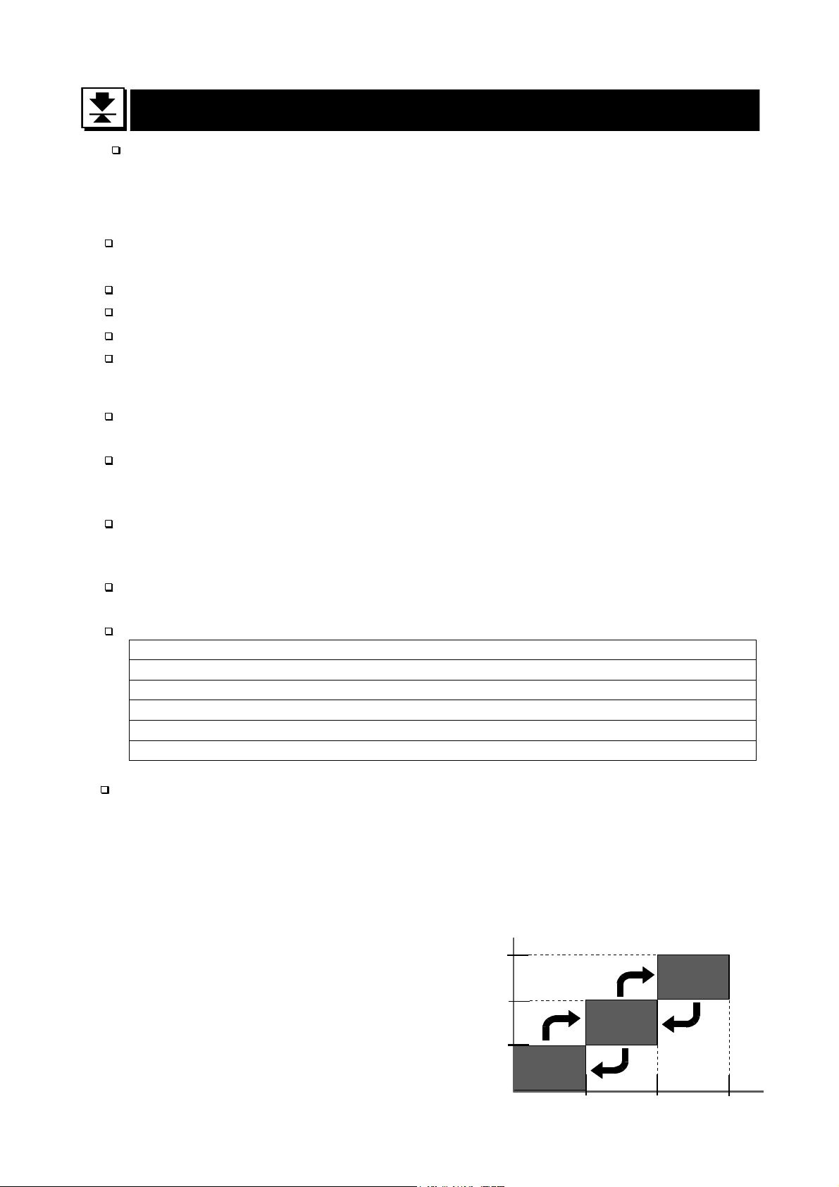
Multi-interval: This is what the minimum display is automatically switched to
depending on the sample weight
Example) With the HV-60KC, weighing capacity is 60kg and minimum display is
0.005kg, 0.01kg or 0.02kg.
Multi-interval: When exceeding the range for small, medium or large, the minimum
display is automatically switched
Point: When a light sample is
weighed, the minimum
display is small.
When a heavy sample is
weighed, the minimum
display is large.
Page 4 HV/HW-C/CP Series
Weighing capacity
60kg
30kg
15kg
Small
range
0.005kg
Large
range
Medium
range
0.02kg0.01kg
Minimum
display
Page 7
3. Precautions
3.1. Installing the Scale
Consider the following conditions to get the most from your scale.
Install the scale where the temperature and relative humidity is stable, there is no draft
and a stable power source is available.
Install the scale on a solid and level surface.
Do not install the scale in direct sunlight.
Do not install the scale near heaters or air conditioners.
Do not install the scale where there is flammable or corrosive gas present.
Do not install the scale near equipment which produces magnetic fields.
Do not install the scale where there is apt to be static electricity, in a place where the
relative humidity is lower than 45% RH. Plastic and isolators are apt to be charged with
static electricity.
The display unit is not water resistant. Use the display unit cover to avoid damage.
Do not use an unstable power source.
Remove the protective film from the weighing pan before use.
3.2. Operating the Scale
Periodically ensure that the weight value is correct.
Calibrate the scale before using and after moving it to another location.
Do not place anything on the pan which exceeds the weighing capacity.
Do not drop anything upon the pan.
Do not use a sharp instrument such as a pencil to press the keys. Press the keys
gently using your finger.
Pressing the ZERO key before each weighing is recommended to prevent possible
error.
Replace the used batteries with four new ones when the
Battery is of type D, Mono, R20P, R20PU or LR20.
mark is displayed.
“lb”
3.3. Storing the Scale
Do not disassemble the scale.
Do not use solvents to clean the scale. Wipe it with a dry lint free cloth or a lint free
cloth which is moistened with warm water and a mild detergent.
The base unit can be cleaned with gentle running tap water. Do not scratch the base
unit with a brash. Allow the unit to dry before using.
Protect the display unit from dust and water.
Remove the batteries from the display unit when the scale is not to be used for a long
time. If you leave the batteries installed, they may leak and damage the scale.
HV/HW-C/CP Series Page 5
Page 8
4. Installing the Scale
4.1. Setting up the Scale
4.1.1. Procedure
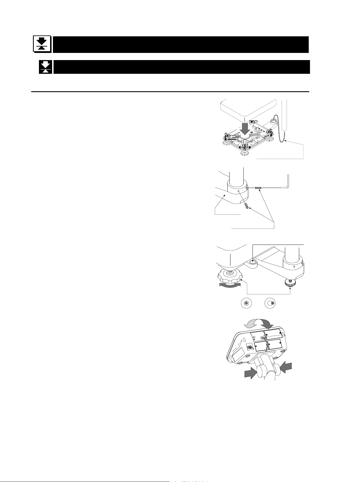
This procedure includes all of the steps for installing
the scale. Therefore, there may be some
unnecessary steps for some models.
Step 1 Take the base unit and pole out, taking care
not to pull on the load cell cable.
Step 2 Place the pan on the base unit. Remove the
protective film from the pan before use.
Step 3 Attach the pole to the bracket of the base
unit, while using care not to damage the load
cell cable.
Insert the remainder of the load cell cable
into the pole.
Affix the pole to the bracket using two Allen
Step 2
Base unit
Pole
Bracket
Pan
Pole
Step 1
Load cell cable
Step 3
3 mm Allen wrench
Allen screws
screws.
* With the HW-10KC, HW-10KCP, HV-15KC
and HV-15KCP, this procedure is not
required because the pole and bracket is a
combined unit.
Step 4 Select a place for installing the scale. Refer
to "3.1. Installing the Scale” .
Step 5 Adjust the level of the base unit using the
bubble spirit level and the leveling feet.
Step 6 Press the caps at the pole top from both
sides and adjust the angle of the display unit.
Step 7 Check the weighing accuracy. If the scale
needs calibration, refer to "14. Calibration".
- The display unit can be adjusted in four steps in the up-and-down direction.
Setting the display sideways is also possible. (Make sure that the pole is secured
Bubble spirit level
Leveling feet
Step 5
OK NG
Step 6
at the lower part of the pole using the allen screws. Do not turn the display unit at a
joint for the pole.)
Page 6 HV/HW-C/CP Series
Page 9
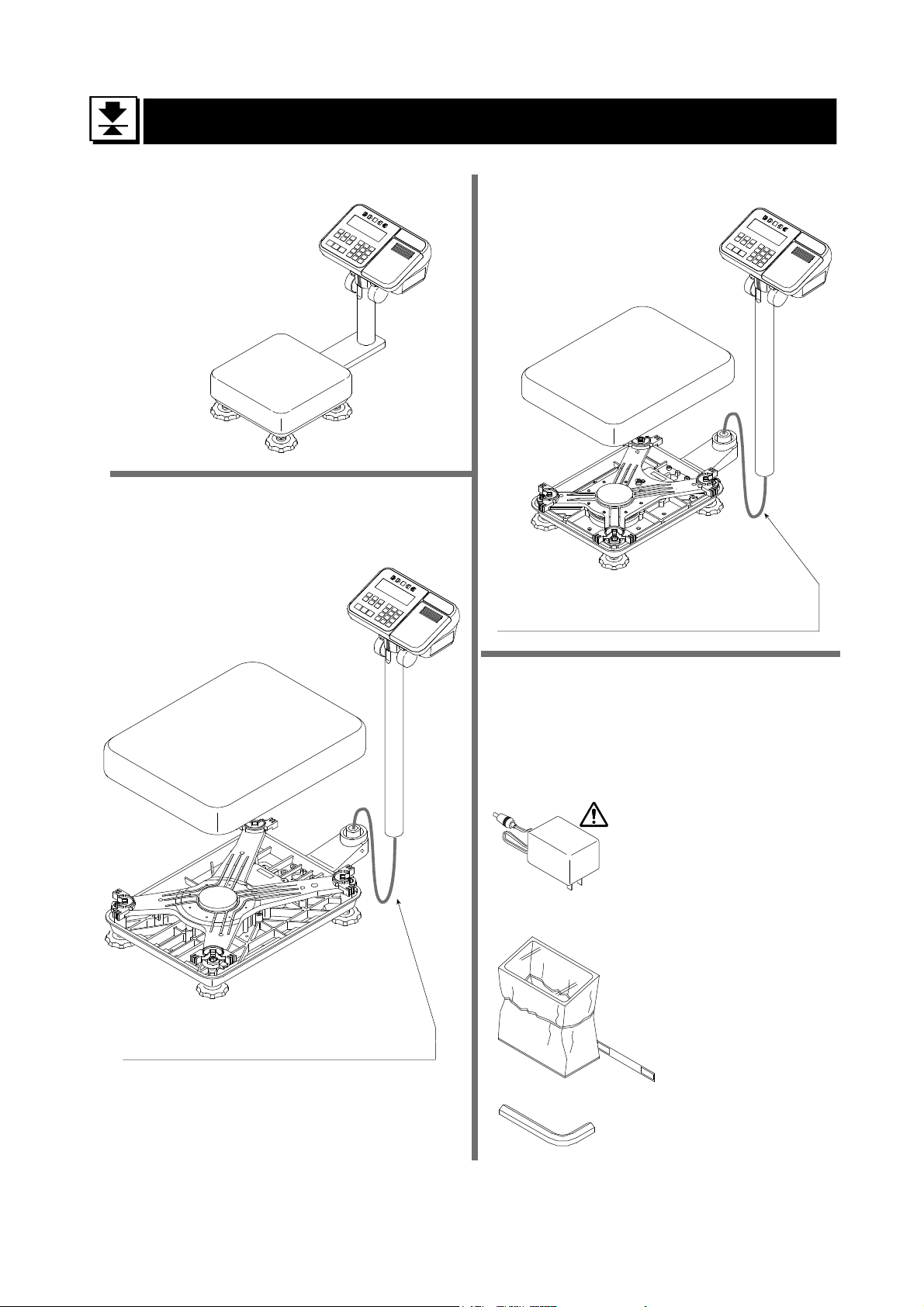
5. Unpacking
Models
HV-15KC
HV-15KCP
HW-10KC
HW-10KCP
Display Unit
Models
HV-60KC HV-60KCP
HW-60KC HW-60KCP
Display Unit
Pan
Base Unit
Models
HV-200KC HV-200KCP
HW-100KC HW-100KCP
HW-200KC HW-200KCP
Pan
Display Unit
Pan
Base Unit
Caution
Do not pull the load cell cable.
Accessories
Refer to "Accessries List" on page 8.
Accessories supplied depend on the scale
model.
AC adapter
Please confirm that the
AC adapter type is
correct for your local
voltage and receptacle
type.
Base Unit
Caution
Do not pull the load cell cable.
HV/HW-C/CP Series Page 7
Display unit cover
14:3003217
Allen wrench
Page 10
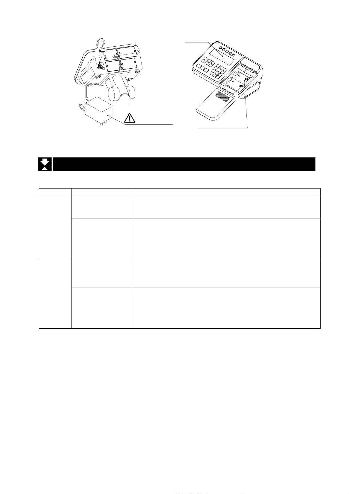
Type C/CP
Please confirm that the main power type or AC adapter type is
correct for your local voltage and receptacle type.
AC adapter
LCD
Type C
Batteries
(Not included)
5.1. Accessories and Options List
Accessories List
Type Models Accessories (Quantity)
HV-15KC
HW-10KC
C
HV-60KC
HV-200KC
HW-60KC
HW-100KC
HW-200KC
HV-15KCP
HW-10KCP
CP
HV-60KCP
HV-200KCP
HW-60KCP
HW-100KCP
HW-200KCP
- Display unit cover (1)
- AC Adapter (1)
- Instruction manual (1)
- Display unit cover (1)
- Allen wrench (1)
- AC Adapter (1)
- Instruction manual (1)
- Display unit cover (1)
- AC Adapter (1)
- Instruction manual (1)
- Special roll paper (1)
- Display unit cover (1)
- Allen wrench (1)
- AC Adapter (1)
- Instruction manual (1)
- Special roll paper (1)
Page 8 HV/HW-C/CP Series
Page 11
Options List
Order code
HVW
-02CB USB interface
HVW
-03C RS-232C interface
HVW
-04C Comparator relay output / Buzzer / Contact input
HVW
-08C
HVW
-11C Wall mounting kit
HVW
-13 Roller conveyor for HV-200KC, HW-100KC and HW-200KC
HVW
-14 Roller conveyor for HV-60KC and HW-60KC
Option name
Extension load cell cable (For weighing capacity of 10 kg to 200 kg)
* When the scale is installed using this cable, the scale requires
recalibration.
AX-KO2466-200
RS-232C cable, D-sub 25 pin, 2 m
RS-232C cables are also available in lengths of 5 and 10 m.
Note OP-16 is factory-installed.
For handling HVW-11C, 13 and 14, refer to the relevant option manual.
Consumables
AX-PP147-S Special roll paper for the built-in printer (set of 5 rolls)
A
HV/HW-C/CP Series Page 9
Page 12
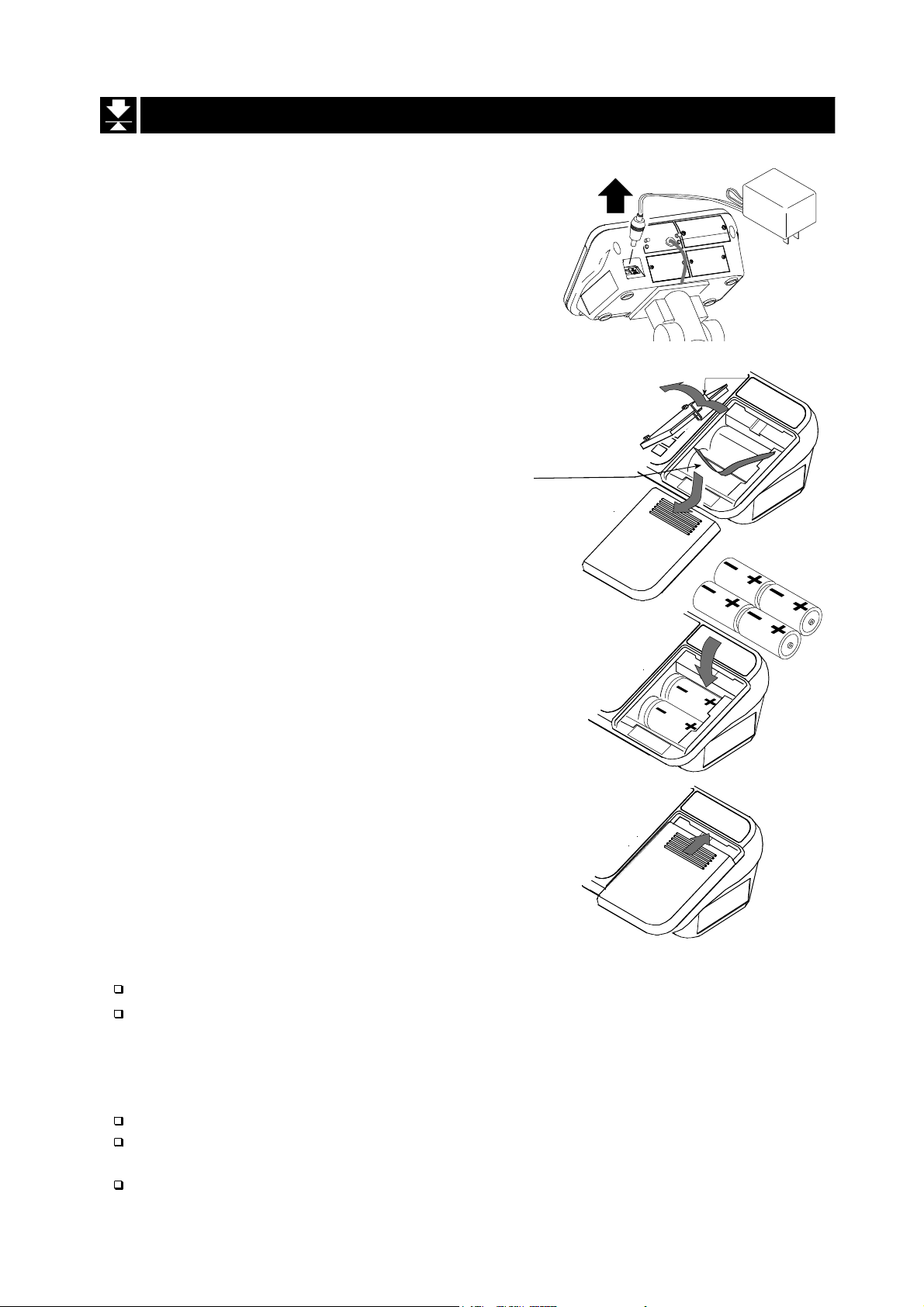
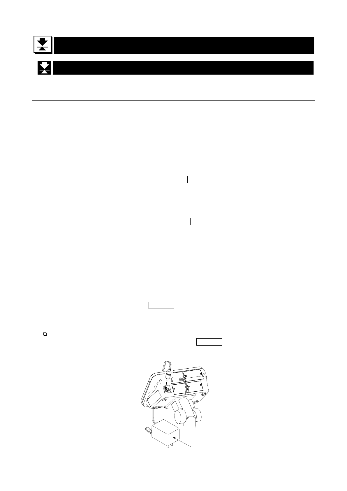
5.2. Installing the Batteries for Type C
Step 1 Turn off the display.
Remove the AC adapter.
Step 2 Press and slide the ext. cover to open it.
Press the hook of the int. cover to the left
side and lift it.
Step 1
Int. cover
Step 2
Battery case
Step 2
Ext. cover
Step 3
AC adapter
Remove
Hook
Batteries
Step 3 Insert four new batteries with proper polarity
(+,-). Battery is of type D, Mono, R20P ,
R20PU or LR20.
Step 4
Step 4 Close the covers in reverse order of step 2.
Cover
Caution
Replace used batteries with four new ones, when
Do not mix used and new batteries. It may cause damage to the batteries or
the scale, if used.
Check the battery direction. If the batteries are installed in the wrong
direction, it may cause battery leakage. If the direction of a single battery is
wrong, the scale may work only temporarily.
The battery life depends on the ambient temperature.
Remove the batteries from the display unit, when the scale is not to be used
for a long time. They may leak and cause damage.
Damage which is due to battery leakage is not covered under warranty.
is displayed.
“lb”
Page 10 HV/HW-C/CP Series
Page 13
5.3. Removing the Pole
Caution
Remove the AC adapter and batteries before removing the pole.
When removing the load cell cable, do not pull on the load cell cable
connector forcibly and do not pull on the wires of the cable.
Do not bend the cable forcibly. Use care so that the load cell cable does not
touch the pan inside the base unit.
Avoid dust, static electricity and high humidity (or condensation) because the
inside of the display unit is sensitive.
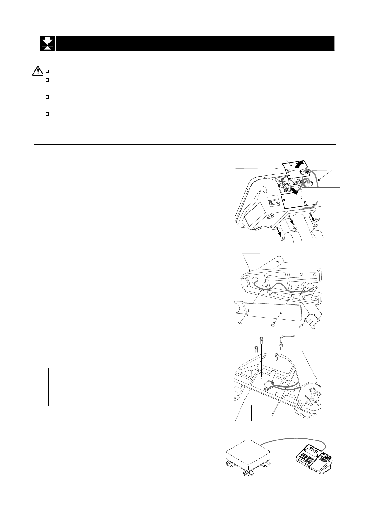
5.3.1. Procedure
Step 1 Turn the scale off.
Remove the AC adapter and batteries.
Step 2 Open the rear cover of the display unit.
Disconnect the load cell cable connector gently
(perpendicularly and do not pull toward you).
Step 3 Remove the four 4 mm screws, which are used
to attach the display unit to the pole.
Step 4 Remove the ferrite core and the cable clamp
from the load cell cable.
Step 5 (HV-60KC, HV-60KCP, HW-60KC, HW-60KCP,
HV-200KC, HV-200KCP, HW-100KC, HW-100KCP,
HW-200KC and HW-200KCP only)
Remove the 3 mm screws from the bottom
cover of the bracket.
Step 6 Carefully remove the load cell cable from the
pole and the bracket. Particularly with
HW-10KC, HW-10KCP, HV-15KC and HV-15KCP,
take care not to pull on the connector forcibly.
Step 7 Arrange the cable so that it does not touch the
pan in the base unit. The untied cable is
approximately 2 m. The optional extension load
cell cable (HVW-08C) is 5 m long.
Step 8 Remove the bracket from the base unit. An
Allen wrench is required.
HV-15KC/HV-15KCP
HV-60KC/HV-60KCP
HW-10KC/HW-10KCP
HW-60KC/HW-60KC
5 mm Allen wrench 6 mm Allen wrench
HV-200KC/HV-200KCP
HW-100KC/HW-100KCP
HW-200KC/HW-200KCP
Step 9 Wind the cable through the ferrite core two
times. Affix the cable to the rear cover using the
cable clamp.
Step 10 Connect the cable to the connector. Close the
rear cover.
Step 11 Check the weighing accuracy.
Rear cover
Cable clamp
Connector
4 mm screw
Bracket (Middle and large sized models)
Pole
Bottom cover
3 mm screws
Allen screw
Bracket
Load cell
cable
Ferrite core
Wind up 2 times
Allen wrench
HV/HW-C/CP Series Page 11
Page 14
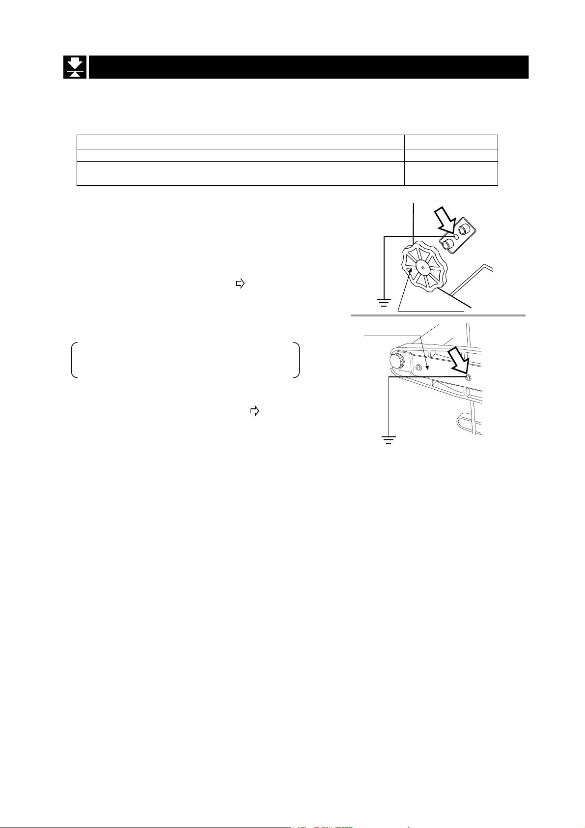
5.4. Grounding the scale
When using where there may be static electricity, ground the scale.
The grounding procedure depends on the scale model. Refer to the table below.
These procedures are only for grounding part of the scale.
Models Refer to
HV-15KC/HV-15KCP/ HW-10KC/HW-10KCP
HV-60KC/HV-60KCP/HV-200KC/HV-200KCP
HW-60KC/HW-60KCP/HW-100KC/HW-100KCP/HW-200KC/HW-200KCP
Procedure A
HV-15KC/HV-15KCP/HW-10KC/HW-10KCP
(
)
Secure the grounding cable using a M4 screw in the
screw hole between the two hexagon bolts on the
base unit bottom side. (Part of “ ”)
Procedure B
HV-60KC/HV-60KCP/HV-200KC/HV-200KCP
HW-60KC/HW-60KCP/HW-100KC/HW-100KCP
HW-200KC/HW-200KCP
Secure the grounding cable using the screw that
secures the under cover. (Part of “ ”)
Under cover
Procedure A
Procedure B
Levering feet
Base unit
bottom side
Base unit
bottom side
Page 12 HV/HW-C/CP Series
Page 15
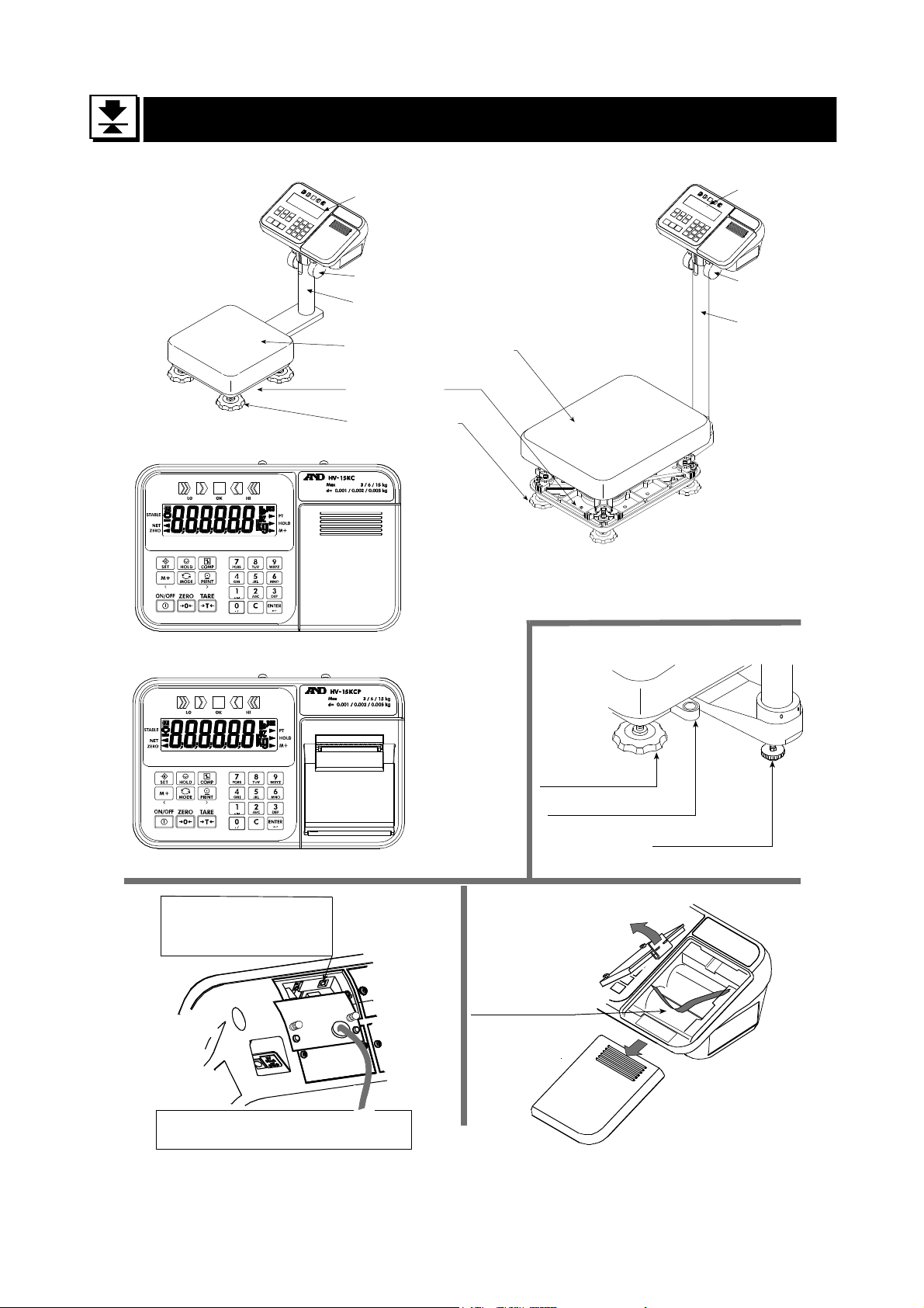
6. Description of Each Part
Models
HV-15KC
HV-15KCP
HW-10KC
HW-10KCP
Type C
Type CP
CAL switch
Calibrating the scale
to weigh correctly.
Caution
The certified mass is required.
Display Unit
Cap
Pole
Pan (Weighing Pan)
Base Unit
Leveling Foot
Models
HV-60KC HV-60KCP
HV-200KC HV-200KCP
HW-60KC HW-60KCP
HW-100KC HW-100KCP
HW-200KC HW-200KCP
Leveling Foot
Bubble Spirit Level
Type C
Battery Case
Display Unit
Cap
Pole
Leveling Foot
HV/HW-C/CP Series Page 13
Page 16
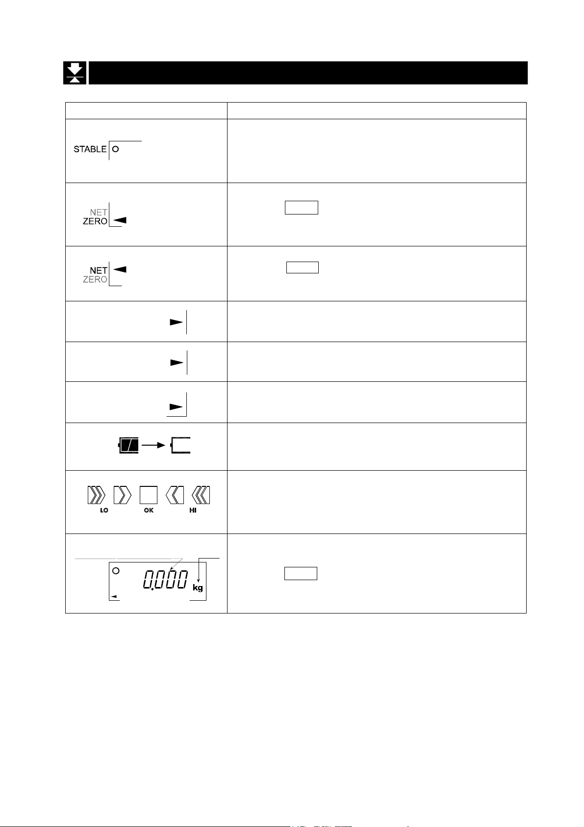
6.1. Display and Symbols
Display and Symbols Description
Stability mark
When the current weight value is stable, this mark is
displayed. It means a proper condition that this value is
readable.
Zero point mark
When the ZERO key is pressed with nothing on the pan,
this mark is displayed. The zero point is the fundamental
starting point to weigh anything.
Net mark
When the
Used to indicate that the mass of the container placed
on the pan has been subtracted from the gross value.
Preset tare mark
PT
HOLD
Accumulation mark
M+
While a tare with digital input is displayed, this mark
blinks.
Hold mark
While the display is held, this mark is displayed.
While the accumulation function is used, this mark is
displayed.
Low battery mark for type C
When the battery is depleted (becoming low voltage),
this mark is displayed. Replace with four new batteries.
Comparator indicator
When using the comparator function, the result is
indicated after the weight value is compared with the
upper and lower limits.
TARE key is pressed, this mark is displayed.
A
A
A
A
A
A
A
A
A
A
A
A
A
A
A
A
A
A
A
A
Weighed mass value
STABLE
ZERO
Page 14 HV/HW-C/CP Series
unit
Zero point (Example)
When the ZERO key is pressed with nothing on the pan,
the zero point mark and the stability mark are displayed.
A
A
A
A
A
Page 17
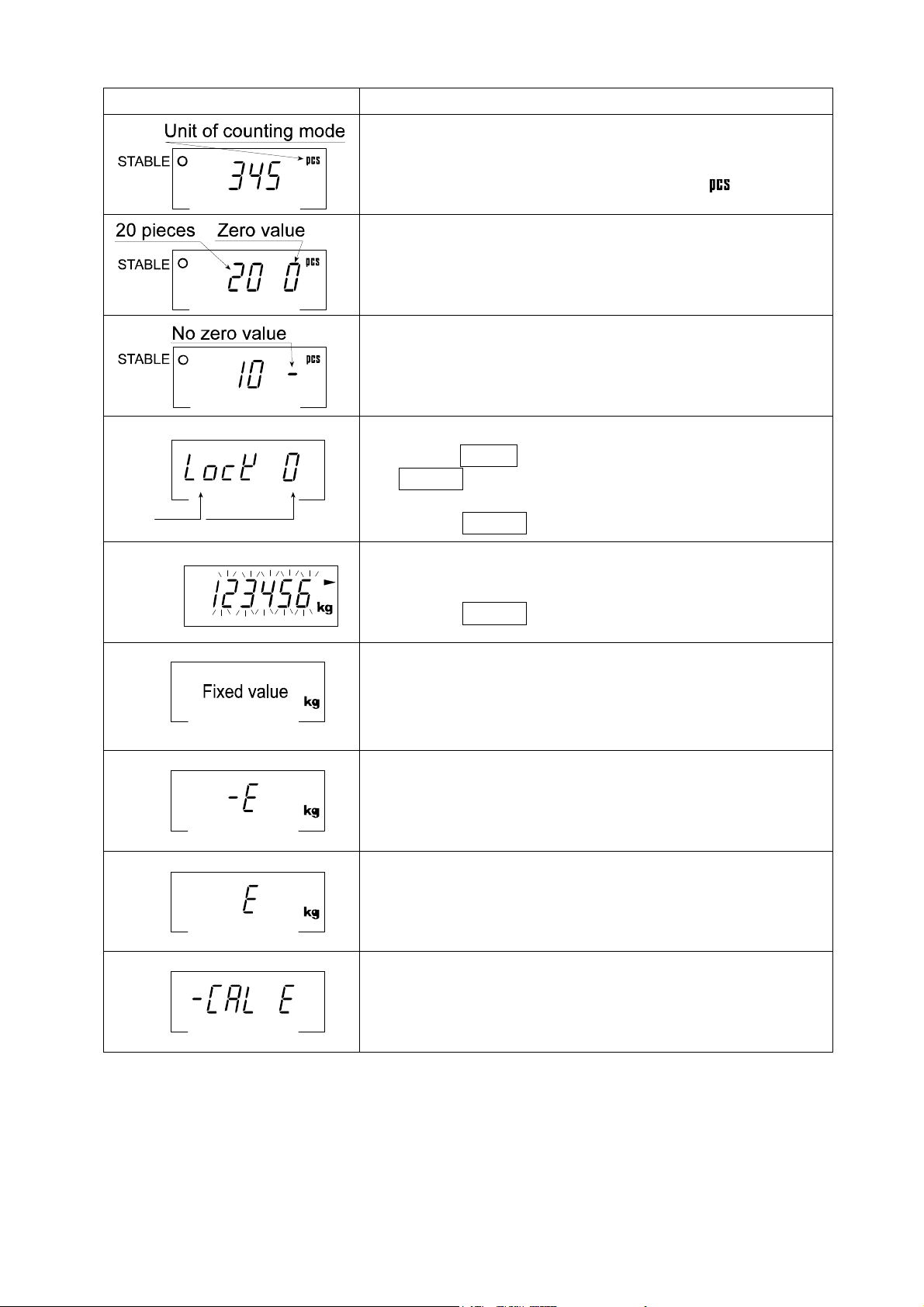
Display and Symbols Description
Counting mode (Example)
This mode uses the stored unit mass and counts the
number of articles on the pan. The unit is .
Storing the unit mass for the counting mode (Example)
The unit mass is stored, using 20 pieces of samples.
The zero value means that no articles are on the pan.
Storing the unit mass for the counting mode (Example)
The unit mass is stored, using 10 pieces of samples.
Sign "-" means that something is placed on the pan.
Item
Example
The "digit" is a unit of display, and is equivalent to the minimum measurable mass.
The " nearly-zero " or zero band is within ±5 digits from zero point in the unit of kg.
Parameter
Function settings (Example)
- Press the MODE key to select the item, and then press
the ENTER key to finalize the selection.
- Enter a parameter using the numerical keypad.
- Press the ENTER key to store the new parameters.
While preset tare setting (Example)
PT
- Enter a setting value using the numerical keypad.
- Press the ENTER key to store the new tare.
Hold display (Example)
The hold display is set using Hold of the function table.
When the weight value is "nearly-zero" (within the zero
band) or changes more than 25% +30 digits, the hold is
canceled.
Weighing error
Check the base unit and the weighing pan.
Overload display
Remove anything that is on the pan.
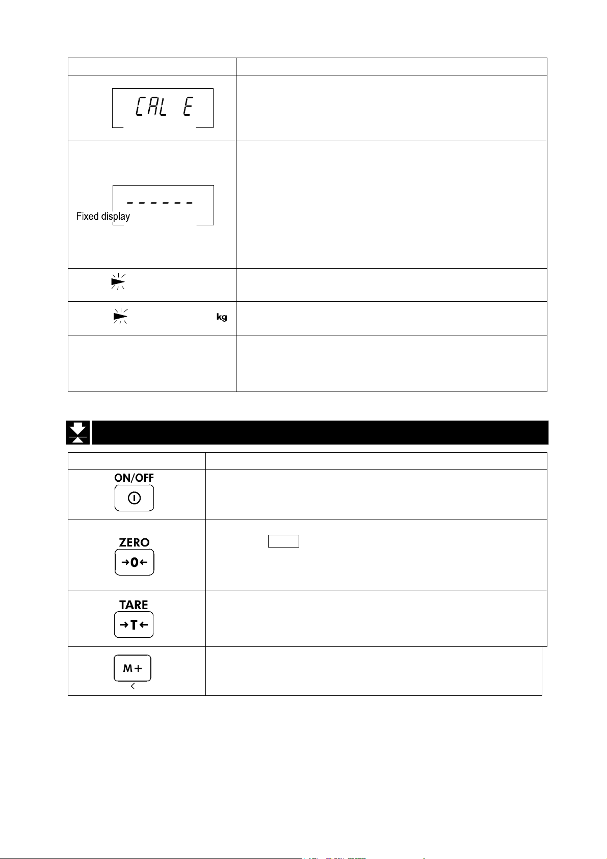
Calibration error
The calibration mass is too light.
Check the base unit and the weighing pan.
A
A
A
A
A
A
A
A
A
A
A
A
A
A
A
A
A
A
A
A
A
A
A
A
A
A
A
A
A
A
A
A
A
A
A
A
A
A
HV/HW-C/CP Series Page 15
Page 18
Display and Symbols Description
Blinking
Blinking
e.g. CAP. MAX. 3/6/15kg d=1/2/5g
M+
M+
and lighting up
Calibration error
The calibration mass is too heavy.
Check the base unit and the weighing pan.
Does not display zero when the scale is turned on.
Remove anything that is on the weighing pan.
Perform zero point calibration.
Or
The weight value is unstable due to drift or vibration
when the scale is turned on.
A breeze or vibration may be affecting the
measurement.
Check around the weighing pan.
Accumulated data count
Total mass value of the accumulated data
The weighing range and measurable minimum mass.
Example: Displays the weight value by 5 g up to 15 kg.
Displays the weight value by 2 g up to 6 kg.
Displays the weight value by 1 g up to 3 kg.
A
A
A
A
A
A
A
A
A
A
A
A
A
A
A
6.2. Keys
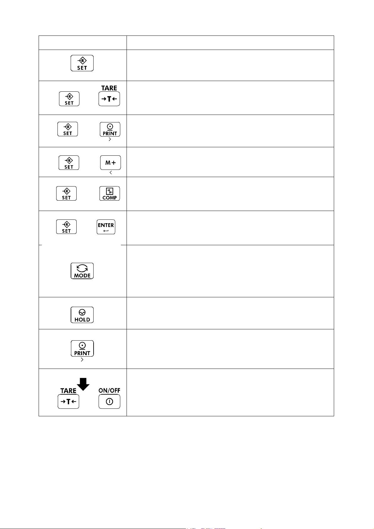
Display and Symbols Description
TARE key
ON/OFF key
The scale is in standby status when power is connected using
the AC adapter.
ZERO key
When the
scale displays the mass value of zero and the zero point mark.
If the scale is in tare in this time, the tare value is cleared.
When accumulation is displayed, the accumulation is cleared.
Canceling the mass of a container which is placed on the pan
and does not weigh its mass.
Note The tare reduces the weighing range.
Adds to the accumulated data.
ZERO key is pressed with nothing on the pan, the
A
A
A
A
A
A
A
A
A
A
A
Page 16 HV/HW-C/CP Series
Page 19
Display and Symbols Description
SET key
When setting the upper/lower limit, switch between + and -.
Press
and
hold
Press
and
hold
Press
and
hold
Press
and
hold
and
press
and
press
and
press
and
press
Enters preset tare setting mode
Performs paper feed at the built-in printer
Displays the accumulated results
Sets upper/lower limit values for comparator
Press
and
hold
Press
and
hold
and
press
Display off
and
press
Proceeds to unit mass storing when using counting mode
MODE key
- Switches the mode (unit) to be displayed
- The mode (unit) is maintained in non-volatile memory, so
the scale displays using the most recently used mode
(unit) when turning on the power next time
- Used as key to select the items at each setting.
HOLD key
Holds the display. Refer to function settings for details.
PRINT key
Prints out the value displayed or outputs it as data. However,
those operations differ depending on function settings.
Enters function settings
HV/HW-C/CP Series Page 17
Page 20
7. Basic Operation
7.1. Turning the Scale on/off and Weighing
7.1.1. When Using the AC Adapter
Step 1 Ground the scale.
Step 2 Confirm that nothing is placed on the pan.
Step 3 Confirm that local voltage and receptacle type are correct.
Step 4 The scale turns on/off using the ON/OFF key alternately.
Step 5 Check the accuracy of weighing. Allow 30-minute warm up before calibration.
Step 6 With nothing on the pan, press the ZERO key to display zero.
Step 7 Place an article to be weighed on the pan gently.
Step 8 Wait for the stability mark to be displayed. Read the weight value.
Step 9 Remove the article from the pan.
Step 10 Turn the scale off using the ON/OFF key.
Memo
With the AC adapter connected, the power is off at the scale, but not from the AC
adapter, after the scale is turned off using the
completely, disconnect the AC adapter.
ON/OFF key. To shut down the power
AC adapter
Page 18 HV/HW-C/CP Series
Page 21
7.1.2. Type C with Batteries
Step 1 Install four new batteries. Refer to "5.2. Installing the Batteries for Type C".
Step 2 Confirm that nothing is placed on the pan.
Step 3 The scale turns on/off using the ON/OFF key alternately.
Step 4 Check the accuracy of weighing. Allow 30-minute warm up before calibration.
Step 5 With nothing on the pan, press the ZERO key to display zero.
Step 6 Place an article to be weighed on the pan gently.
Step 7 Wait for the stability mark to be displayed. Read the weight value.
Step 8 Remove the article from the pan.
Step 9 Turn the scale off using the ON/OFF key.
Caution
When is displayed, this means the batteries will run out soon.
Replace used batteries with four new ones when
Battery life depends on the ambient temperature.
Remove the batteries from the display unit when the scale is not to be used
for a long time. The batteries may leak and cause damage.
is displayed.
“lb”
HV/HW-C/CP Series Page 19
Page 22
7.2. Tare (And Net Display)
The "tare" is used to cancel the mass of a container, which is placed on the pan to
contain the article to be weighed.
Caution
The tare reduces the weighing range.
The current tare value is reset by pressing the ZERO key or turning the scale
off. (Reset value is zero.)
The storable preset tare value must be within the minimum weighing range.
7.2.1. Tare Input by Weighing
Step 1 Place the container on the pan.
Step 2 Wait for the stability mark to be displayed. Press the TARE key. The display
becomes zero and the net mark is displayed.
Step 3 Place an article to be weighed into the container. Wait for the stability mark to be
displayed and read its net display.
Step 4 Remove the article and the container from the pan.
7.2.2. Digital Input (Preset Tare)
Step 1 Press and hold the SET key and press the TARE key.
Then the blank or stored tare value is displayed. The blank display means that the
tare value is zero (reset value). And PT blinks.
Step 2 Enter the preset tare value using the numerical keypad.
Step 3 Press the ENTER key to store the new preset tare value.
Then the scale displays the net value (the gross weight value minus the tare value).
Step 4 Place an article to be weighed into the container. Wait for the stability mark to be
displayed and read its net display.
Step 5 Remove the article and the container from the pan.
Page 20 HV/HW-C/CP Series
Page 23

7.3. Switchimg the mode
kg weighing
+
+
+
Counting mode Unit mass storing mode
Ib weighing
OZ weighing
Ib-OZ weighing
Number of
accumulations *1
Upper/lower limit values
setting mode
Preset tare setting mode
* The scale displays the number of accumulations and an accumulation value only when
accumulation data exists.
+
* Ib-OZ display is available only with
HV-15KC, HV-15KCP, HW-10KC and
HW-10KCP
Accumulation
value *1
HV/HW-C/CP Series Page 21
Page 24

8. Counting Mode
The counting mode is the function to convert the total mass value (total weight) of
articles to a count, when each article has the same mass value.
To use this function, store a unit mass in advance.
Even if the AC adapter or the batteries is removed, the unit mass is maintained in
non-volatile memory.
8.1. Storing a Unit Mass
Step 1 Press the MODE key to display the unit .
Step 2 Press the SET and ENTER key to enter the mode
that stores a unit mass.
Step 3 Press the SET key to select the number of samples.
The greater the quantity of samples, the greater the
accuracy of the count.
5 pieces, 10 pieces, 20 pieces, 50 pieces,
100 pieces
Number of samples
A container(bowl)
Step 4 Place the container on the pan.
Press the TARE key.
Step 5 Place the number of samples selected at step 3.
Wait for the stability mark to be displayed. Press the
ENTER
key to store. The count is displayed.
Counting mode
STABLE
STABLE
Pan
STABLE
Zeroing value
Caution
When the sample total mass value is too small and
it is not possible to calculate a unit mass, the scale
displays lo ut and returns to step 3. Increase the
number of samples. More than 10 digits of the total
sample mass, in the unit of kg, are required.
When the unit mass is too light to store, the scale
displays lo ut . In this case, the unit mass will not be
stored even if the number of samples is increased.
Pressing the MODE key, after lo ut is displayed,
displays the next unit.
Step 6 Remove the samples and the container from the pan.
Page 22 HV/HW-C/CP Series
STABLE
Count
Note
The pan shape depends
on the scale model.
Page 25

8.2. Counting the Number of Articles
Step 1 Press the MODE key to display the unit .
Step 2 Store the unit mass of the article.
Refer to "8.1. Storing a Unit Mass"
Step 3 Place the container on the pan.
Press the TARE key.
Step 4 Place articles in the container. Wait for the stability
mark to be displayed and read the count.
Step 5 Remove the articles and the container from the pan.
Counting mode
Storing a unit mass
A container(bowl)
Pan
STABLE
Zeroing value
STABLE
Note
The pan shape depends
on the scale model.
HV/HW-C/CP Series Page 23
Page 26

9. Accumulation Function
This function counts the number of times articles are weighed, calculates the total mass
value and can display the number (accumulation count) and accumulated mass value.
The accumulation function is displayed with up to 6 digits. The balance can not display 7 or
more digits, therefore the leading digits are not displayed.
Example: With 60K type, when importing the data of 17 accumulations of up to 60kg (60.000
To use this function, set the parameters of the "Accumulation function ( 5um )" in the
function table in advance.
To use the built-in printer, set the parameters of the " Built-in printer output mode
( prtp 9 )" in the function table in advance.
The accumulation count and accumulated mass value are stored in the scale even if
the power is removed.
Operation and Keys
The display of the accumulation count has a blinking M+ without a unit.
The display of the accumulated mass value has a unit and a blinking M+.
Press the SET and M+ key to display the accumulation count and accumulated mass
value.
Press the ZERO key in the accumulation function (with a blinking M+) to reset the
current function (The count and accumulated mass value become zero.)
When the PRINT key is pressed, the accumulation results (date, data number and
weighing value) are printed by the built-in printer (HV/HW-CP models). Date is set at
function table 5tdp .
Caution
The accumulation function is available only when weighing is performed in the
same unit.
X 17=1020.000), the balance displays this as “020.000”.
Parameter List and Word Definition
The "nearly-zero" is within ±5 digits from the zero point in the unit of kg.
The "digit" is a unit of display, and is equivalent to the minimum measurable mass.
The "zero point" is the fundamental starting point to weigh anything.
Function table Description
5um 0
5um 1
5um 2
Page 24 HV/HW-C/CP Series
Accumulation function not used.
The scale accumulates the data, if the M+ key is pressed, when
the display is a positive stable value and not nearly-zero. The next
accumulation can be performed after the display becomes
nearly-zero or a negative value.
The scale accumulates the data, if the M+ key is pressed, when the
display is a stable value and not nearly-zero. The next accumulation
can be performed after the display becomes nearly-zero.
A
A
A
A
A
A
A
A
A
Page 27

Function table Description
When the display is a positive stable value and not nearly-zero, the
A
scale accumulates the data automatically. The next accumulation
5um 3
can be performed after the display becomes nearly-zero or a
negative value.
When the display is a stable value and not nearly-zero, the scale
accumulates the data automatically. The next accumulation can be
performed after the display becomes nearly-zero.
5um 4
Use Recording the number and mass of articles removed from
the pan. (Place the articles on the pan. Press the TARE key
at each removal.)
A
A
A
A
A
HV/HW-C/CP Series Page 25
Page 28

10. Comparator
Five-level, three-level and seven-level (portion weighing mode) comparators are
available.
Each comparator mode compares the weight value against the preset limit values and
outputs the results using LEDs (yellow / green / red).
When the optional comparator relay output (HVW-04CJA) is installed, the results are
output as a relay signal.
Five-level comparator mode:
Uses four comparator values to
compare the weight value and outputs
results in five levels of LOLO, LO, OK,
HI and HIHI.
Three-level comparator mode:
Uses two comparator values (upper
and lower limit values) to compare the
weight value and outputs results in
three levels of LO, OK and HI.
Seven-level comparator mode (portion weighing mode):
Uses six comparator values to compare
the weight value and outputs results in
seven levels of over in the negative
value, level 1 (LOLO), level 2 (LO),
Level 3 (OK), level 4 (HI), level 5 (HIHI)
and over in the positive value.
To use the comparator modes, the function settings “Cp-l” and “Cp” must be
specified and the comparator values must be set.
Using the function setting “
0: five-level comparator mode
1: three-level comparator mode
2: Seven-level comparator mode (portion weighing mode)
Using the function setting “
0: No comparison (comparator mode disabled).
1: To compare all data.
2: To compare all stable data.
3: To compare all data which are more than or equal to +5d, or less than
or equal to -5d.
4: To compare stable data which are more than or equal to +5d, or less
than or equal to -5d.
5: To compare all data which are more than or equal to +5d.
6: To compare stable data which are more than or equal to +5d.
d = minimum display in kg (Refer to “16. SPECIFICATIONS”.)
Also in the counting mode, “d” is equal to the minimum display of kg mode.
Page 26 HV/HW-C/CP Series
Cp-l”, select a comparator mode.
Cp”, select comparison conditions.
Page 29

10.1. The formula to compare
Comparison is performed using the formula listed below and the results are output.
Five-level comparator mode
Results Comparison formula LED display
LOLO
LO Displayed value < LO limit value
OK LO limit value ≤ Displayed value ≤ HI limit value
HI HI limit value < Displayed value
HIHI
Three-level comparator mode
Results Comparison formula LED display
LO
OK LO limit value ≤ Displayed value ≤ HI limit value
HI
Seven-level comparator mode (portion weighing mode)
Results Comparison formula LED display
None
LOLO
(Level 1)
LO
(Level 2)
OK
(Level 3)
HI
(Level 4)
HIHI
(Level 5)
None
The comparator values are common to the weighing and counting mode.
Ignore the decimal point when setting the comparator values.
The comparator values are maintained even if the power is turned OFF.
Judgment order of comparison is from the top row to the bottom in the comparator
mode tables
The entered comparator values are not judged. Even if the upper limit value is less
than the lower limit value, no error will be output.
Displayed value < LOLO limit value
(Or over in the negative value)
HIHI limit value < Displayed value
(Or over in the positive value)
Displayed value < LO limit value
(Or over in the negative value)
HI limit value < Displayed value
(Or over in the positive value)
Displayed value < Level 1 lower limit value
(Or over in the negative value)
Displayed value < Level 2 lower limit value
Displayed value < Level 3 lower limit value
Level 3 lower limit value ≤ Displayed value ≤ Level
3 upper limit value
Level 3 upper limit value < Displayed value
Level 4 upper limit value < Displayed value
Level 5 upper limit value < Displayed value
(Or over in the positive value)
( Red LED on)
( Yellow LED on)
( Green LED on))
( Yellow LED on)
( Red LED on)
( Red LED on)
( Green LED on))
( Red LED on)
( No LEDs on)
( Red LED on)
( Yellow LED on)
( Green LED on))
( Yellow LED on)
( Red LED on)
( No LEDs on)
10.2. Entering the comparator values
1. In the weighing mode, press and hold the SET key and press COMP key to enter
the comparator value setting mode.
2. Enter the comparator values using the following keys.
10 to 9 To enter numerical value
HV/HW-C/CP Series Page 27
Page 30

1C To cancel settings
SET To switch between + and -
ENTER To store setting values
* Each time the SET key is pressed, “-” switches between being lit and off at the
first digit. “-”being lit means a minus setting.
3. When the setting is complete, “
weighing mode. (At this time, power-on-zero is not performed.)
Example of five-level
comparator mode
With the HW-60KC, set as
follows.
LOLO
LO 10.000 kg
HI
HIHI 12.000 kg
8.500 kg
10.500 kg
Example of three-level
comparator mode
(upper/lower limit mode)
With the HV-200KC, set as
follows.
end
LO 148.85 kg
HI
152.5 kg
” is displayed and the scale returns to the
Example of seven-level
comparator mode (portion
weighing mode)
With the HV-15KC, set as follows.
Level 1
(LOLO) 0.500 kg or more
Level 2
(LO) 1.000 kg or more
Level 3
(OK) 1.500 kg to 2.000 kg
Level 4
(HI) up to 2.500 kg
Level 5
(HIHI) up to 3.000 kg
Weighing
mode
Weighing
mode
Weighing
mode
+
Press
To set the LOLO
limit vaue
Press
To set the LO
limit vaue
Press
+
Press
To set the LO
limit vaue
Press
To set the HI
limit vaue
Press
+
To set the HI
Press
limit vaue
Weighing
mode
Press
To set level 1
lower limit vaue
Press
To set level 2
lower limit vaue
Press
To set level 3
lower limit vaue
Press
To set the HIHI
limit vaue
Press
* With the HV-C models, the
scale changes the
minimum display digit
depending on the display
range. Enter 0 for the final
digit.
To set level 3
upper limit vaue
Press
To set level 4
upper limit vaue
Weighing
mode
Press
To set level 5
upper limit vaue
Press
Page 28 HV/HW-C/CP Series
Weighing
mode
Page 31

11. Auto-tare
The HV/HW-C/CP series has an auto-tare function to be used with the comparator mode
enabled. Using this function in check weighing, the scale automatically tares, then displays “OK”
for a certain amount of sample and repeats this process for the next weighing.
Start with display zero after tare operation. Place or take away objects until the
comparison result will show OK. When the stable display is maintained for the duration
specified in the function setting “at-t”, the scale will automatically tare the weight, show
zero and be ready for next weighing.
In some countries or areas, the auto-tare function can not be used on the Legal for Trade
models and the selection in the function settings “at”, “at-t” and “at-f” is not available.
To use the auto-tare function, set the function settings below.
Cp 1:
Compare all weighing data (other settings may be used depending on the
application).
at 1: Auto-tare function enabled.
at-t 0 ~ 9:
Take-away check weighing “Cp-p 1” (Example with “Cp-l 0” setting)
Take-away check weighing (negative comparison) is the way to compare the
negative weight while taking away objects from a container.
Set the function “Cp-p 1” together with the auto-tare function enabled “at 1”. In this
operation mode, the scale operates as “take-away the objects” “OK and stable”
“auto-tare” “take-away the objects” ······.
In this setting, the polarity of LOLO, LO, HI, and HIHI limit values are ignored and the
scale shows the comparator results as below.
Note: To start the take-away check weighing, be sure to use the TARE key to tare the
weight of the container filled with objects. The ZERO key may zero the display,
and the scale goes below the zero point by taking out the objects. Then, the
auto-tare function or TARE key does not work.
When the function “at-f 1 Tares the initial (container) weight.” is selected:
To start the auto-tare function, usually the container (filled with objects) will be placed on the
weighing pan and its weight must be tared using the TARE key. When the function “at-f
Select the timing to tare automatically to avoid the wrong tare operation, for
example; too early to tare, to take a longer time to go to the next weighing.
1” is selected, the scale will tare the initial (container) weight automatically.
When all load on the weighing pan is removed, the scale will return to the zero point and
the tare weight will be automatically cleared. If the scale does not return to the zero point,
press the
If the scale is equipped with the optional USB interface (HVW-02CBJA) or optional
RS-232C serial interface (HVW-03CJA), the OK weighing data can be output
automatically. Set the function setting “prt1” or “prt2”to 7 or 8.
ZERO key to clear the tare weight.
HV/HW-C/CP Series Page 29
Page 32

11.1. Built-in Printer for HV/HW-CP Series
To use the printer, set the parameter of the "Print mode ( prtp )" in the function table.
To print the date, set the parameter of the "Date ( Cl adj )" in the function table.
Specification
Type Line thermal dot type
Characters 32 characters per line (when using double height and width
size, 16 characters per line)
Width of roll paper 58 mm
Accessories Special roll paper (1 roll)
Consumables
Special roll paper AX-PP147-S (set of 5 rolls)
Operation and Print Samples
Press and hold the SET key and press the PRINT key. Paper feed is performed.
The following example is when the print mode in the function settings is selected.
Printing example for prtp 1~8
1.181 kg
Printing example for 5tdp 3
2016/ 8/31
14:56:51
Printing example for 5idp 1 (Id number = 000123)
2016/ 8/31
14:56:51
000123
Printing example for 5um 4、prtp 9
590 PC
1.180 kg
1.180 kg
2016/ 8/31
14:56:51
000123
001 1.181 kg
002 1.180 kg
003 1.180 kg
←Weight
←Number of times
←Date
←Time
←Weight
←Date
←Time
←Id
←Weight
Printing is automatically done when
accumulating.
Date, time and Id are only printed at first time.
Page 30 HV/HW-C/CP Series
Page 33

Installing the roll paper
Step 1 Pull the printer cover toward you to open.
Step 2 Install the roll paper so that the end of the paper is
at the top.
Step 3 Close the printer cover.
Step 4 W hen the roll paper is installed successfully, the
built-in printer automatically feeds out the paper.
HV/HW-C/CP Series Page 31
Page 34

12. ID Number and GLP
The ID number is used to identify the scale when Good Manufacturing Practice (GMP)
or Good Laboratory Practice (GLP) is used. The following GMP data is output to the
built-in printer (HV/HW-CP series) or a personal computer using the RS-232C interface.
The results of calibration (“Calibration report”)
The results of calibration test (“Calibration test report”)
The “Start block” and “End block” for GLP data
12.1. Setting the ID number
Step 1. With the power turned OFF, press and hold the
TARE key and press the ON/OFF key to turn the
power ON and enter the function setting mode.
ba5fnc appears.
Step 2. Press the MODE key several times to display
id .
Step 3. Press the ENTER key.
Enter the ID number using the following keys.
1M+ key To move the blinking digit to the left
PRINT key To move the blinking digit to the right
Numerical keypad To set a value of the blinking digit
See the table below for the
“Display character set.”
Step 4. Press the ENTER key to store the settings.
id appears after end .
Step 5. Press the ON/OFF key to turn the power OFF or
press the ZERO key.
Press
several
times
Set using corresponding
keys.
Display character set
0 1 2 3 4 5 6 7 8 9 -
0 1 2 3 4 5 6 7 8 9 - a b C d e f g H i j k l m n o p q r s t U v w x y z
“” : Space
Page 32 HV/HW-C/CP Series
A B C D E F G H I J K L M N O P Q R S T U V W X Y Z
Page 35

12.2. Setting the clock
The clock can only be set for built-in printer models (-CP models).
Step 1 Turn off the display.
Press and hold the TARE key and press the
ON/OFF key to turn on the display and enter
function setting mode. 1ba5fnc appears.
Step 2 Press the MODE key several times to display Cl adj .
Step 3 Press the ENTER key to enter date confirmation
mode.
* To only set time without changing date, press the
MODE key
- Date setting mode -
Step 4 Press the ENTER key to enter date setting mode.
Set the date using the following keys.
1M+ key To move the blinking digit to the left
PRINT key To move the blinking digit to the right
Numerical keypad To set a value for the blinking digit
1ZERO key To proceed to step 5 without
storing the setting.
Step 5 Press the ENTER key after finishing setting. A
setting value is registered, and the scale proceeds to
time confirmation mode after displaying end .
* To return to date confirmation mode, press the
MODE key.
-Time setting mode -
Step 6 Press the ENTER key to enter time setting mode.
Set time using the following keys.
1M+ key To move the blinking digit to the left
PRINT key To move the blinking digit to the right
Numerical keypad To set a value for the blinking digit
1ZERO key To proceed to step 7 without
storing the setting.
Step 7 Press the ENTER key after finishing setting to
register the set value. The scale displays Cl adj
after displaying end .
Step 8 Press the 1ON/OFF key to turn off the power or press the 1ZERO key
Press several
times
Date
confirmation
mode
Date
setting
mode
Set using
corresponding keys
Time
confirmation
mode
Time
setting
mode
Set using
corresponding keys
*
HV/HW-C/CP Series Page 33
Page 36

12.3. GMP report
To print the GMP report to an AD-8127 printer, select the function setting “inf1 1”
and “inf2 1” and use MODE 3 of the printer.
To output the GMP report to a personal computer, select the function setting “inf1 1”
and “inf2 2.”
Calibration report
Step 1. Perform calibration according to “13.2.
Complete Calibration Procedure.”
Step 2. end appears when the calibration is
complete.
Step 3. gmp appears and calibration report is
output.
Step 4. Cal appears again. Remove the weight.
Press the ON/OFF key to turn the power
OFF or press the CAL switch.
AD-8127 format “inf1 1” General format “inf2 2”
Manufacturer
Model
Serial number
ID number
Date
Time
Calibration
executed
Calibration weight
Column for
signature
: Space, ASCII 20h
CR: Carriage return, ASCII 0Dh
LF: Line feed, ASCII 0Ah
To output the results
`~~~~~~~~~~A~&~D<CRLF>
MODEL~~~ HV-15KC<CRLF>
S/N~~~~ 6A6123456<CRLF>
ID~~~~~~~~ABCDEF<CRLF>
DATE<CRLF>
<CRLF>
TIME<CRLF>
<CRLF>
CALIBRATED(EXT.)<CRLF>
CAL.WEIGHT<CRLF>
~~~~ ~+15.000~k
SIGNATURE<CRLF>
<CRLF>
<CRLF>
g<CRLF>
---------------~<CRLF>
<CRLF>
<CRLF>
Page 34 HV/HW-C/CP Series
Page 37

Calibration test report
The calibration test mode is used to compare a calibration weight with the calibration
test data weighed by the scale.
This test does not perform calibration.
Step 1. In the weighing mode, press and hold the
CAL switch until CC appears, and release
the switch.
The calibration test mode is not available when
the function setting “inf1 0” or “inf2 0” is
selected.
Step 2. Press the ENTER key to display CC 0 .
Step 3. If necessary, change the value of the calibration
weight as described in “13.2.4. Span Calibration”
Step 4. With nothing on the pan, press the ENTER
key. The zero point is measured and the
measured value with the unit “kg” is displayed for
a few seconds. Then, the value of the calibration
weight is displayed.
Step 5. Place a weight of the same value as displayed
on the pan and press the ENTER key to
measure it. The measured value with the unit
“kg” is displayed for a few seconds.
Step 6. end appears.
Step 7. gmp appears and calibration test report is
output.
Step 8. CC appears again. Remove the weight.
Press the ON/OFF key to turn the power OFF
or press the CAL switch.
Change the calibration
weight value if necessary
CAL
Release the keys
Weighing unit
Weighing unit
To output the results
HV/HW-C/CP Series Page 35
Page 38

AD-8127 format “inf1 1” General format “inf1 2”
: Space, ASCII 20h
CR: Carriage return, ASCII 0Dh
LF: Line feed, ASCII 0Ah
Manufacturer
Model
Serial number
ID number
Date
Time
Calibration
test
Zero value
Actual weight
value
Calibration weight
Column for
signature
~~~~~~~~~~~A~&~D<CRLF>
MODEL~~~ HV-15KC<CRLF>
S/N~~~~6A6123456<CRLF>
ID~~~~~~~~ABCDEF<CRLF>
DATE<CRLF>
<CRLF>
TIME<CRLF>
<CRLF>
CAL.TEST(EXT.)<CRLF>
ACTUAL<CRLF>
~~~~~~~~0.000~k
~~~~~
TARGET<CRLF>
~~~~~ +15.000~k
SIGNATURE<CRLF>
<CRLF>
<CRLF>
+15.005~kg<CRLF>
---------------~<CRLF>
<CRLF>
<CRLF>
g<CRLF>
g<CRLF>
Output of “Title block” and “End block”
When weight values are recorded as the GMP report,
“Title block” and “End block” are added at the beginning
and at the end of a group of weight values.
Title block
Step 1. In the weighing mode, press and hold the
PRINT key until 5tart appears, and release
the key. The scale outputs the “Title block.”
The scale automatically returns to the weighing
mode.
Step 2. Press the PRINT key or select the auto-print
mode to output the weight values.
ZERO
Press
and hold
To output the "
To output the
Title block
weighing values
"
Page 36 HV/HW-C/CP Series
Page 39

End block
Step 3. Press and hold the PRINT key until
recend appears, and release the key.
Press
and hold
The scale outputs the “End block.”
Step 4. The scale automatically returns to the weighing
To output the "
mode.
AD-8127 format “inf1 1” General format “inf1 2”
: Space, ASCII 20h
CR: Carriage return, ASCII 0Dh
LF: Line feed, ASCII 0Ah
Title
block
Manufacturer
Model
Serial number
ID number
Date
Starting time
Weight data
Ending time
Column for
signature
End
block
~~~~~~~~~~~A~&~D<CRLF>
MODEL~~~ HV-15KC<CRLF>
S/N~~~~6A6123456<CRLF>
ID~~~~~~~~ABCDEF<CRLF>
DATE<CRLF>
<CRLF>
START<CRLF>
TIME<CRLF>
<CRLF>
<CRLF>
ST,+0001.234~k
ST,+0002.345~k
ST,+0003.456~k
ST,+0004.567~k
END<CRLF>
TIME<CRLF>
<CRLF>
SIGNATURE<CRLF>
<CRLF>
<CRLF>
g<CRLF>
g<CRLF>
g<CRLF>
g<CRLF>
---------------~<CRLF>
<CRLF>
<CRLF>
End block
"
HV/HW-C/CP Series Page 37
Page 40

13. Calibration (Adjusting the Scale)
The scale is an instrument which weighs the "weight" and displays its "mass".
Calibration is the adjustment function so that the scale can weigh correctly.
Three steps of calibration are available
Gravity Acceleration Correction ... The function to correct the scale’s local gravity
acceleration, so that the scale functions
correctly when the calibrated scale has been
moved to a distant place.
Refer to the "Gravity Acceleration Table" on
the next page.
Calibration of the Zero Point ......... The function to adjust the zero point, so that
the zero point mark is displayed when there is
nothing on the pan.
Comment The zero point is the fundamental starting point
to weigh anything and influences the
performance of scale.
Span Calibration.............................. The function to adjust the span with a
calibrated mass, so that the scale can
accurately weigh anything within the weighing
capacity.
Comment Span means the range of weighing capacity.
Use a calibration mass heavier than two thirds
of the weighing capacity.
Caution
Check the accuracy of weighing periodically. Calibrate the scale, if it has
been moved to another location or the environment has changed.
Gravity acceleration correction is not required, when the scale is calibrated
with the calibration mass at the place where the scale is used.
Page 38 HV/HW-C/CP Series
Page 41

13.1. Gravity Acceleration Table
Amsterdam 9.813 m/s2 Manila 9.784 m/s2
Athens 9.800 m/s2 Melbourne 9.800 m/s2
Auckland, NZ 9.799 m/s2 Mexico 9.779 m/s2
Bangkok 9.783 m/s2 Milan 9.806 m/s2
Birmingham 9.813 m/s2 New York 9.802 m/s2
Brussels 9.811 m/s2 Oslo 9.819 m/s2
Buenos Aires 9.797 m/s2 Ottawa 9.806 m/s2
Calcutta 9.788 m/s2 Paris 9.809 m/s2
Chicago 9.803 m/s2 Rio de Janeiro 9.788 m/s2
Copenhagen 9.815 m/s2 Rome 9.803 m/s2
Cyprus 9.797 m/s2 San Francisco 9.800 m/s2
Djakarta 9.781 m/s2 Singapore 9.781 m/s2
Frankfurt 9.810 m/s2 Stockholm 9.818 m/s2
Glasgow 9.816 m/s2 Sydney 9.797 m/s2
Havana 9.788 m/s2 Tainan 9.788 m/s2
Helsinki 9.819 m/s2 Taipei 9.790 m/s2
Kuwait 9.793 m/s2 Tokyo 9.798 m/s2
Lisbon 9.801 m/s2 Vancouver, BC 9.809 m/s2
London (Greenwich) 9.812 m/s2 Washington, DC 9.801 m/s2
Los Angeles 9.796 m/s2 Wellington, NZ 9.803 m/s2
Madrid 9.800 m/s2 Zurich 9.807 m/s2
HV/HW-C/CP Series Page 39
Page 42

13.2. Complete Calibration Procedure
13.2.1. Gravity Acceleration Correction
Step 1 Turn on the display.
Open the rear cover of the display unit. Locate the
CAL switch inside.
Press the CAL switch to enter the calibration mode.
Then Cal 0 is displayed.
Step 2 Press the MODE key to enter the gravity acceleration
correction mode. Press the ENTER key to make the
numerical value blink and proceed to input mode.
Step 3 Set your local gravity acceleration using the numerical
keypad.
CAL switch
Enter using numerical
keypad
Step 4 Press the ENTER key to store the new value.
The display returns to gravity acceleration display
after displaying end .
Step 5 Press the CAL switch again to finish gravity
acceleration correction.
13.2.2. Preparation
The power is automatically
turned off.
CAL switch
Step 6 Confirm the environmental conditions as follows:
Maintain a constant temperature and stable power.
Install the scale on a solid floor where there is no draft, vibration, strong magetic
fields or direct sunlight.
Refer to "4.1. Installing the Scale".
Step 7 Keep the display turned on for at least 30 minutes to warm up the scale.
Page 40 HV/HW-C/CP Series
Page 43

13.2.3. Calibration of the Zero Point
Step 8 After 30-minute warm up, press the CAL
switch to display Cal .
Press the ENTER switch to display Cal 0 .
Step 9 Confirm that nothing is placed on the pan.
Wait for the stability mark to be displayed.
Press the ENTER key.
The scale stores the current condition as
the zero point.
Step 10 Calibration of the zero point is finished. To
exit the calibration mode, proceed to step
14.
STABLE
STABLE
Stability mark
Note
The pan shape depends
on the scale model.
Weighing mode
CAL switch
Nothing on
the pan
13.2.4. Span Calibration
Step 11 Set the value of the calibration mass
using the numerical keypad. (The initial
value depends on the scale model.)
Step 12 Place the mass on the pan which was set
at step 11. Wait for the stability mark to be
displayed. Press the ENTER key.
The scale then calculates the span and
stores it.
Step 13 The scale displays Cal after displaying
end to finish setting.
Remove the mass from the pan.
Enter using numerical
keypad
Weignt value
15kg
STABLE
Stab ility mark
Step 14 Press the CAL switch to finish calibraiton.
HV/HW-C/CP Series Page 41
CAL switch
The power is automatically
turned off.
Page 44

14. Function Table
The function table is used to store and refer items that determine the performance of
the scale. Each item has a parameter.
The parameters are stored in the scale even if the power is removed.
Item
Parameter
14.1. Parameter Setting Procedure
Step 1 Turn off the display.
Press and hold the TARE key and press the ON/OFF
key to display software version p-XXX .
Press the MODE key to enter function setting mode.
Class ba5fnc .
Step 2 Press the MODE key to select the desired class, and
then press the ENTER key.
Step 3 The first item of class is displayed. Press the MODE
Display off
Press
and hold
and press
Class
Items
key to select the desired item, and then enter a value
using numerical keypad.
Enter using
numerical
key pad
Step 4 Press the ENTER key to store. The display returns to
class after displaying end .
Step 5 Press the ZERO key to return to normal weighing mode.
Weighing value
Page 42 HV/HW-C/CP Series
Page 45

A
A
14.2. Parameter List
Class
ba5fnc
■
"Nearly-zero" is within ±5 digits (five times the minimum mass that can be weighed) from
Items
Key lock
lock
utomatic power
off
poff
utomatic power
on
p-on
trc
Stability band width
5t-b
Stability band time
5t-t
Weighing
stabilization level
cond
Back light control
lit
Back light
brightness
l-i
pnt
Automatic tare
at
Parameter
: factory settings
zero point in the unit kg.
0■ Functions with all the keys
1 Functions with the ON/OFF, ZERO, TARE, HOLD, M+ and PRINT key
2 Functions with the ON/OFF, ZERO, TARE key
0■ OFF
1 After 5 minuets
2 After 10 minuets
3 After 15 minuets
4 After 30 minuets
5 After 60 minuets
0■ OFF
ON * The scale automatically turns the power on by connecting
1
0 OFF Zero tracking
■
1
ON
0■ ±0.5 digit
1 ±1 digit
2 ±2 digits
0 0.5 second
1■ 1.0 seconds
2 1.5 seconds
0 Fast
1
2■
3
4 Slow
0 Always turned off
1 Always lit
2■ Turns off 5 seconds after stabilizing
3 Turns off 10 seconds after stabilizing
4 Turns off 15 seconds after stabilizing
5 Turns off 30 seconds after stabilizing
0 Dark
1
2■
3
4 Bright
0■ Dot(.) Decimal point
1 Comma(,)
0■ OFF
1 ON
to the power using the AC adapter.
Details and usage
HV/HW-C/CP Series Page 43
Page 46

Class
Items
Interval until
making automatic
tare
at-t
Tare on initial load
at-f
Accumulation mode
5um
Hold condition
Hold
Bba5fnc
buzz
External contact
input 1
Con1
External contact
input 2
Con2
Comparator
judgment value
Cp-l
Cp fnc
■
: factory settings
"Nearly-zero" is within ±5 digits (five times the minimum mass that can be weighed) from
Parameter
0 0 second
1 0.5 second
2■ 1.0 second
3 1.5 seconds
4 2.0 seconds
5 2.5 seconds
6 3.0 seconds
7 4.0 seconds
8 5.0 seconds
9 10 seconds
0■ OFF
1 ON
0 OFF
1■ Accumulates by M+ key when the value is +, excluding near zero
2 Accumulates by M+ key when the value is + or -, excluding near zero
3 Accumulates automatically when the value is +, excluding near zero
4 Accumulates automatically when the value is + or -, excluding near zero
0■ OFF
1 Holds or releases by the HOLD key
2 Automatically holds when detecting a stabilization
0■ Not sounded Buzzer
Method for
LED to be lit
0■ None
1 ON/OFF
2 ZERO
3 TARE
4 MODE
5 PRINT
6 M+
7 HOLD
0■ None
1 ZERO
2 TARE
3 MODE
4 PRINT
5 M+
6 HOLD
0■ Five-level comparator
1 Three-level comparator (upper and lower limits)
2 Seven-level comparator (portion weighing)
* When lighting up the LED registered to be lit, the
buzzer sounds. Set it using the numerical keypad. The
LEDs at 1:LOLO, 2:LO, 3:OK, 4:HI or 5:HIHI are lit.
Details and usage
zero point in the unit kg.
Page 44 HV/HW-C/CP Series
Page 47

Class
Cp fnc
5if
dout
Items
Comparator
judgment
condition
Cp
Comparator
brightness
Cp-i
Comparator reversal
Cp-p
Baud rate 1
bp51
(OP-ch1)
Bit length, parity1
btp1
(OP-ch1)
Communication format 1
5if1
(OP-ch1)
Baud rate 2
bp52
(OP-ch2)
Bit length, parity 2
btpr2
(OP-ch2)
Communication
format 2
5if2
(OP-ch2)
Built-in printer
communication format
5ifp
Output mode 1
prt1
(OP-ch1)
■
: factory settings
Parameter
0 OFF
1■ Compares all
2 Compares all the stabilized data
3 Compares all the data, excluding from –4 digits to +4 digits
4 Compares the stabilized data, excluding from –4 digits to +4 digits
5 Compares all the data more than +5 digits
6 Compares the stabilized data more than +5 digits
0 Dark
1
2■
3
4 Bright
0■ OFF
1 ON
0■ 2400
1 4800
2 9600
0■ 7bit/even
1 7bit/odd
2 8bit/non
0■ Format 1
1 Format 1, existing returned value
2 UFC
0■ 2400
1 4800
2 9600
0■ 7bit/even
1 7bit/odd
2 8bit/non
0■ Format 1
1 Format 1, existing returned value
2 UFC
0■ Format 1
1 UFC
0 Stream mode (commands)
Commands (Output by a “Q” command from
1
the OP-ch1 or OP-ch2)
Commands (Output by a “Q”
2
command from the OP-ch1)
Commands (Output by a “Q”
3
command from the OP-ch2)
■
4
Outputs by the PRINT key (commands)
5 Outputs data at auto print setting, +5 digits or more and stabilization (commands)
Outputs data at auto print setting, +5 digits or more, or -5 digits or less and
stabilization (commands)
6
Outputs data at auto print setting, +5 digits or more and stabilization when the
7
comparator is OK (commands)
Outputs data at auto print setting, +5 digits or more, or -5 digits or less and
8
stabilization when the comparator is OK (commands)
9
Prints an accumulation value when the accumulation operation is made (commands)
Details and usage
* Output depending on output
command
(output command:
Q,A,N,?H3,?H2,?H1,?L1,?L2,?L3)
HV/HW-C/CP Series Page 45
Page 48

Class
r
dout
■
: factory settings
Items
Time and date
adding
5td1
(OP-ch1)
ID number adding
5id1
(OP-ch1)
GMP output
inf1
(OP-ch1)
Output mode
prt2
(OP-ch2)
Time and date
adding
5td2
(OP-ch2)
ID number adding 2
5id2
(OP-ch2)
GMP output 2
inf2
(OP-ch2)
Paramete
■
0
Do not output the date and time
1 Outputs time (ESC T) *2
2 Outputs date (ESC D) *2
3 Outputs the date and time (ESC D,ESC T) *2
4 Outputs time (RTC) *1
5 Outputs date (RTC) *1
6 Outputs the date and time (RTC) *1
■
0
Do not output the ID
1
Outputs the ID
■
0
Not output
1 Output (ESC D, ESC T output) *2 AD-8127 format
2 Output (DATE,TIME output) General format
3 Output (RTC output) *1
0 Stream mode (commands)
Commands (Output by a “Q” command
from the OP-ch1 or OP-ch2)
1
Commands (Output by a “Q”
2
command from the OP-ch1)
Commands (Output by a “Q”
3
command from the OP-ch2)
■
4
Outputs by the PRINT key (commands)
5
Outputs data at auto print setting, +5 digits or more and stabilization (commands)
Outputs data at auto print setting,
6
stabilization (commands)
Outputs data at auto print setting, +5 digits or more and stabilization when the comparator
7
is OK (commands)
Outputs data at auto print setting,
8
stabilization when the comparator is OK (commands)
Prints an accumulation value when the accumulation operation is made (commands)
9
■
0
Do not output the date and time
1 Outputs time (ESC T) *2
2 Outputs date (ESC D) *2
3 Outputs the date and time (ESC D,ESC T) *2
4 Outputs time (RTC) *1
5 Outputs date (RTC) *1
Outputs the date and time (RTC) *1
6
■
0
Do not output the ID
1
Outputs the ID
■
0
Not output
1 Output (ESC D,ESC T output) *2 AD-8127 format
2 Output (DATE,TIME output) General format
Output (RTC output) *1
3
Details and usage
* 1 RTC: built-in clock
* 2 ES(T, ESC 1)
Use date and time of calendar function of the AD-8127.
* Output depending on output
command
(output command:
Q,A,N,?H3,?H2,?H1,?L1,?L2,?L3)
+5 digits or more, or -5 digits or less
+5 digits or more, or -5 digits or less
and
and
Page 46 HV/HW-C/CP Series
Page 49

r
r
Class
dout
Items
Built-in printer print
mode
prtp
Time and date
adding
5tdp
3
ID number adding
5idp
GMP print
infp
Double height and
width size
d5cp 1
Built-in printer
label mode
labl
Line feed of printer
prlf
■
: factory settings
Paramete
0 Not printed
Commands (print by a “Q”
1
command from the OP-ch1 o
OP-ch2)
Commands (print by a “Q”
2
command from the OP-ch1)
Commands (print by a “Q”
3
command from the OP-ch2)
■
4
Prints by the PRINT key
5 Prints data at auto print setting, +5 digits or more and stabilization
Prints data at auto print setting, +5 digits or more, or -5 digits or less and
6
stabilization
Prints data at auto print setting, +5 digits or more and stabilization when
7
the comparator is OK
Prints data at auto print setting, +5 digits or more, or -5 digits or less and
8
stabilization when the comparator is OK
Prints an accumulation value when the accumulation operation is made
9
■
0
Do not print the date and time
1 Prints time (RTC)
2 Prints date (RTC)
Details and usage
* Print depending on output
command
(output command:
Q,A,N,?H3,?H2,?H1,?L1,?L2,?L3)
Prints the date and time (RTC)
■
0
Do not print the ID
Prints the ID
1
■
0
Not print
Print (RTC output)
1
■
0
Standard
Double height and width size
■
0
Thermal paper
Label
1
0 0 lines
1 1 line
■
2
2 lines
~
~
9 9 lines
* Settings for RTC and RTC output (clock function) is available only for built-in printer
model (-CP model)
HV/HW-C/CP Series Page 47
Page 50

15. Options
The scale is equipped with OP-ch1 and OP-ch2 for communication options, and
OP-ch3 only for comparator relay output.
Those options can be combined freely. Combinations such as HVW-02BC×2,
HVW-02CB + HVW-03C or HVW-03CJA×2 are possible.
Only the HVW-04C can be installed with the slot for the OP-ch3.
Installation example
OP-ch1: HVW-03C
OP-ch2: HVW-02CB
OP-ch3: HVW-04C
OP-ch2
OP-ch3
OP-ch1
15.1. Installing an option
Remove the two M3 screws at both side on the panel, and then remove the panel
from the display unit.
Connect the cable located inside the display unit to the connector on the option panel.
Firmly secure the option to the display unit using the two M3 screws.
15.2. HVW-02CB USB Interface
The HVW-02CB is available for duplex communication using a USB interface.
The connector is type B. To connect the HVW-02CB to a PC, “type A male - type B
female” cable sold separately can be used.
When confirming the communication format, refer to “15.5. Communication format”.
To communicate between the scale and PC using the USB interface, it is necessary
to install the specified driver for the HVW-02CB. Download the driver from the A&D
website.
The HVW-02CB can only be connected with a PC. Do not take power from the USB
terminal. Do not connect a device other than a PC to the USB terminal. Doing so may
cause malfunctions.
Page 48 HV/HW-C/CP Series
Page 51

15.3. HVW-03C RS-232C Interface
The HVW-03C is available for duplex communication using RS-232C interface.
The DCE (Data Communication Equipment) connector is type DSUB-9P.
To connect the HVW-03C to an external device, it is necessary to use a
communication cable sold separately.
AX-KO2466-200(2m) / -500(5m) / -1000(10m)
When confirming the communication format, refer to “15.5. Communication format”.
Pin assignment
(DCE)
Signal
name
- -
- -
TXD
RXD
RTS
CTS
DSR
SG
Direction Description
2
3
7
8
6
5
→
←
-
→
←
→
No connection
Transmit data
Receive data
No connection
Signal ground
Data set ready
Request to send
Clear to send
Used internally
Pin No.
1
2 TXD
3 RXD
4
5 GND
6 DSR
7 RTS
8 CTS
9 - -
Names other than TXD and RXD are for the DTE side.
Scale side
Approx.5V
Inside of the scale
External
device
side (DTE)
RXD
TXD
RTS
CTS
DSR
SG
Terminal example
of the external
device side
HV/HW-C/CP Series Page 49
Page 52

15.4.
A
r
HVW-04C Comparator Relay Output / Buzzer / Contact Input
Maximum voltage: 50V DC
Maximum current: 100 mA DC
Maximum ON resistance: 8 Ω
HIHI
HI
OK
LO
ttached terminal
Manufacturer: PHOENIX
Model name: MSTB 2.5/ 6-STF-5.08
1 Relay output HIHI
2 Relay output HI
3 Relay output OK
4 Relay output LO
5 Relay output LOLO
6 Relay common COM
LOLO
Solid sate relay
Inside of
HV/HW-C/CP
Terminal names and wiring example of external contact input plug
External contact input plug
* 3.5mm stereo mini-plug o
equivalent
Con2 terminal
Con1 terminal
GND terminal
Con1 line
Con2 line
GND line
Page 50 HV/HW-C/CP Series
Page 53

15.5. Communication format
Data format
S T
+ 0 0 0 0 0
,
0 0 _ k g CR LF
.
Header Data Unit Terminator
There are 4 headers for the weighing data.
ST: Stable weighing data
QT: Stable counting data
US: Unstable weighing data
OL: Out of weighing range
The data consists of 9 characters including the polarity and decimal point.
There are 5 units.
_ k g: Weighing mode “kg”
_ l b: Weighing mode “lb”
_ o z: Weighing mode “oz”
_ l b-oz: Weighing mode “lb-oz”
_ PC: Counting mode “pcs”
As a terminator, C
is always output.
RLF
Data example
Weighing data “kg” (+) S T
Counting data “pcs” (+) Q T
Out of weighing range (+) O L
HV-C model
When changing number of
digits of the minimum display
S T , + 0 0 1 2 . 3 4 _ _ k g
,
+ 0 0 1 2 . 3 4 5 _ k g
,
+ 0 0 0 1 2 3 4 5 _ P C
,
+ 9 9 9 9 . 9 9 9 _ k g
C
C
C
C
R LF
R LF
R LF
R LF
Data output mode (prt)
Command mode
The scale is controlled by commands that come from an external device such as a
personal computer. For details, refer to “15.5.1. Command mode”.
Stream mode (prt 0)
Data is sent continuously. The data update rate is approximately 10 times per second,
the same as the display refresh rate.
There will be no output during the setting procedures.
Print key mode (prt 4)
When the weight display is stable, data is sent by pressing the PRINT key.
At this time, the display flashes once to indicate that the data is sent.
Auto-print mode + data (prt1 5)
HV/HW-C/CP Series Page 51
Page 54

When the weight display is stable at +5d (d = minimum display in kg) and above, the
data is sent. The next transmission can not occur until after the weight display falls
+4d or below.
Auto-print mode +/- data (prt1 6)
When the weight display is stable at ±5d (d = minimum display in kg) and above +5d
or below -5d, the data is sent. The next transmission can not occur until after the
weight display falls between –4d and +4d.
Auto-print mode + data and OK (prt1 7)
When the weight display is stable and OK as a comparison result at +5d (d =
minimum display in kg) and above, the data is sent. The next transmission can not
occur until after the weight display falls +4d or below.
Auto-print mode +/- data and OK (prt1 8)
When the weight display is stable and OK as a comparison result at ±5d (d =
minimum display in kg) and above +5d or below -5d, the data is sent. The next
transmission can not occur until after the weight display falls between –4d and +4d.
Baud Rate (bp5)
When using HVW-03CJA, select the baud rate according to the device to be connected.
2400 bps (bp5 0) Select 2400 bps to connect to an AD-8127 printer.
4800 bps (bp5 1)
9600 bps (bp5 2)
15.5.1. Command mode
In the command mode, the scale is controlled by commands that come from an external
device such as a personal computer.
Command List
Command Description Remarks
Q Send data immediately.
Z Zero the scale when the weight is stable. Same as the ZERO key.
T Tare the scale when the weight is stable. Same as the TARE key.
U Switch the weighing unit. Same as the MODE key.
CT Clears tare
PT Sets preset tare PT,+000000<CR
><LF>
A Outputs accumulation values
N Outputs the number of accumulations
CA Clears accumulation
ID Sets ID number ID: xxxxxx<CR
?ID Requests ID number
Page 52 HV/HW-C/CP Series
><LF>
Page 55

Command Description Remarks
?PT Outputs preset tare value
When the five-level comparator mode is used:
Not used
?H3
?H2
?H1
?L1
When the three-level comparator mode is used:
Not used
When the seven-level comparator mode is used:
Send the current level 5 upper limit value.
When the five-level comparator mode is used:
Send the current HIHI limit value.
When the three-level comparator mode is used:
Send the current HI limit value.
When the seven-level comparator mode is used:
Send the current level 4 upper limit value.
When the five-level comparator mode is used:
Send the current HI limit value.
When the three-level comparator mode is used:
Not used
When the seven-level comparator mode is used:
Send the current level 3 upper limit value.
When the five-level comparator mode is used:
Send the current LO limit value.
When the three-level comparator mode is used:
Not used
Send a setting value.
Function settings
Five-level (Cp-l 0)
Three-level (Cp-l 1)
Seven-level (Cp-l 2)
?L2
?L3
H3
When the seven-level comparator mode is used:
Send the current level 3 lower limit value.
When the five-level comparator mode is used:
Send the current LOLO limit value.
When the three-level comparator mode is used:
Send the current LO limit value.
When the seven-level comparator mode is used:
Send the current level 2 lower limit value.
When the five-level comparator mode is used:
Not used
When the three-level comparator mode is used:
Not used
When the seven-level comparator mode is used:
Send the current level 1 lower limit value.
When the five-level comparator mode is used:
Not used
When the three-level comparator mode is used:
Not used
When the seven-level comparator mode is used:
Set the level 5 upper limit value.
Set the six-digit value excluding
the polarity and decimal point
HV/HW-C/CP Series Page 53
Page 56

Command Description Remarks
When the five-level comparator mode is used:
Set the HIHI limit value.
H2
H1
L1
L2
When the three-level comparator mode is used:
Set the HI limit value.
When the seven-level comparator mode is used:
Set the level 4 upper limit value.
When the five-level comparator mode is used:
Set the HI limit value.
When the three-level comparator mode is used:
Not used
When the seven-level comparator mode is used:
Set the level 3 upper limit value.
When the five-level comparator mode is used:
Set the LO limit value.
When the three-level comparator mode is used:
Not used
When the seven-level comparator mode is used:
Set the level 3 lower limit value.
When the five-level comparator mode is used:
Set the LOLO limit value.
When the three-level comparator mode is used:
Set the LO limit value.
When the seven-level comparator mode is used:
Set the level 2 lower limit value.
When the five-level comparator mode is used:
Not used
L3
When the three-level comparator mode is used:
Not used
When the seven-level comparator mode is used:
Set the level 1 lower limit value.
Command examples (“_” indicates “Space” (20H).)
The examples below are for the function setting “5if1 1 “ (Reply to commands).
Request the weight data.
Command
Reply
Q CR LF
S T , + 0 0 1 2 . 3 4 5 _ k g CR LF
U S , + 0 0 0 7 . 8 9 0 _ k g CR LF
O L , + 9 9 9 9 . 9 9 9 _ k g CR LF
Stable positive data
Unstable positive data
‘E’ display
Zero the scale. (No reply for the function setting “5if1 0 “.)
Command
Reply
Z CR LF
Z CR LF
The scale is in a condition that zero operation is possible.
Page 54 HV/HW-C/CP Series
Page 57

Tare the scale. (No reply for the function setting “5if1 0 “.)
Command
Reply
T CR LF
T CR LF
The scale is in a condition that tare operation is possible.
Switch the weighing unit. (No reply for the function setting “5if1 0 “.)
Command
Reply
U CR LF
U CR LF
Five-level comparator mode…Not used
Three-level comparator mode…Not used
Seven-level comparator mode…Send the current level 5 upper limit value.
Command
Reply
? H 3 CR LF
H 3 , + 0 0 0 5 0 0 CR LF
Five-level comparator mode…Send the current HIHI limit value.
Three-level comparator mode…Send the current HI limit value.
Seven-level comparator mode…Send the current level 4 upper limit value.
Command
Reply
? H 2 CR LF
H 2 , + 0 0 0 4 0 0 CR LF
Five-level comparator mode…Send the current HI limit value.
Three-level comparator mode…Not used
Seven-level comparator mode…Send the current level 3 upper limit value.
Command
Reply
? H 1 CR LF
H 1 , + 0 0 0 3 0 0 CR LF
Five-level comparator mode…Send the current LO limit value.
Three-level comparator mode…Not used
Seven-level comparator mode…Send the current level 3 lower limit value.
Command
Reply
? L 1 CR LF
L 1 , + 0 0 0 2 0 0 CR LF
Five-level comparator mode…Send the current LOLO limit value.
Three-level comparator mode…Send the current LO limit value.
Seven-level comparator mode…Send the current level 2 lower limit value.
Command
Reply
? L 2 CR LF
L 2 , + 0 0 0 1 0 0 CR LF
Five-level comparator mode…Not used
HV/HW-C/CP Series Page 55
Page 58

Three-level comparator mode…Not used
Seven-level comparator mode…Send the current level 1 lower limit value.
Command
Reply
? L 3 CR LF
L 3 , + 0 0 0 0 0 0 CR LF
Five-level comparator mode…Not used
Three-level comparator mode…Not used
Seven-level comparator mode…Set the level 5 upper limit value.
(No reply for the function setting “5if1 0 “.)
Set the six-digit value excluding the polarity and decimal point.
Command
Reply
H 3 , + 0 0 0 5 0 0 CR LF
H 3 , + 0 0 0 5 0 0 CR LF
Five-level comparator mode…Set the HIHI limit value.
Three-level comparator mode…Set the HI limit value.
Seven-level comparator mode…Set the level 4 upper limit value.
(No reply for the function setting “5if1 0 “.)
Set the six-digit value excluding the polarity and decimal point.
Command
Reply
H 2 , + 0 0 0 4 0 0 CR LF
H 2 , + 0 0 0 4 0 0 CR LF
Five-level comparator mode…Set the HI limit value.
Three-level comparator mode…Not used
Seven-level comparator mode…Set the level 3 upper limit value.
(No reply for the function setting “5if1 0 “.)
Send the six-digit value excluding the polarity and decimal point.
Command
Reply
H 1 , + 0 0 0 3 0 0 CR LF
H 1 , + 0 0 0 3 0 0 CR LF
Five-level comparator mode…Set the LO limit value.
Three-level comparator mode…Not used
Seven-level comparator mode…Set the level 3 lower limit value.
(No reply for the function setting “5if1 0 “.)
Send the six-digit value excluding the polarity and decimal point.
Command
Reply
L 1 , + 0 0 0 2 0 0 CR LF
L 1 , + 0 0 0 2 0 0 CR LF
Five-level comparator mode…Set the LOLO limit value.
Page 56 HV/HW-C/CP Series
Page 59

Three-level comparator mode…Set the LO limit value.
Seven-level comparator mode…Set the level 2 lower limit value.
(No reply for the function setting “5if1 0 “.)
Send the six-digit value excluding the polarity and decimal point.
Command
Reply
L 2 , + 0 0 0 1 0 0 CR LF
L 2 , + 0 0 0 1 0 0 CR LF
Five-level comparator mode…Not used
Three-level comparator mode…Not used
Seven-level comparator mode…Set the level 1 lower limit value.
(No reply for the function setting “5if1 0 “.)
Send the six-digit value excluding the polarity and decimal point.
Command
Reply
L 3 , + 0 0 0 0 0 0 CR LF
L 3 , + 0 0 0 0 0 0 CR LF
Replies to the commands other than examples above when the function setting “5if1
“ is selected.
1
The scale is not in a state where a command could be executed. Then, the scale will reply “I”.
Command
Reply
Z CR LF
I CR LF
The scale is not in a condition that zero operation is possible.
Command does not exist for the HV/HW-C/CP series. Then, the scale will reply “?”.
Command
Reply
B CR LF
? CR LF
The scale received an undefined command.
When the function setting “5if1 0 “ is selected, undefined commands are ignored and no
reply is sent.
HV/HW-C/CP Series Page 57
Page 60

15.6. Using UFC (Universal Flex Coms) Function
The UFC function allows you to print out as you format the printer (UFC format).
The scale can store the UFC format as text data. It will include parameters to replace
Store Text Data into the Scale Memory
with the count data, weight data and so on.
The maximum number of text data is 300 characters.
Using “PF” command, the text data has to be sent to the scale in advance.
When the PRINT key is pressed or by auto-print mode, the scale will send the stored
text data with the parameters replaced by the original data.
The UFC format data can be sent through one RS-232C or USB interface only.
Set one of 5if1 or 5if2 at "2" to send the data. The others must be set at "0" or "1".
When printing using the built-in printer, set 5ifp to "1".
Command P F , $ P C , ‘ T E X T ‘ , # 2 0 , $ S P
$ C R , $ L F , $ W T , $ C R , $ L F
Reply P F
C
LF
R
C
R
Terminator
LF
The “PF” command sends text data that will include:
Parameters for the scale data and control codes
Parameter Data & Code Parameter Data & Code
$PC Count $DT Date
$WT Weight $TM Time
$TR Tare weight in use $CM Comma
$TL Total count $SP Space
$AN Accumulation numbers $CR Carriage Return
$ID ID number in use $LF Line Feed
$CP Comparator result
These parameters must be used capital letters.
ASCII text string
Text string is described in single quote marks as ‘Data’.
The single quote itself is written as ’’(2 single quotes).
Example: Text ‘ABC’ is described as ‘’’ABC’’’.
The ASCII hexadecimal code
The ASCII hexadecimal codes are written in the form “#" + 2 hexadecimal digits.
This will mainly be used to send control codes that can’t be described as a text string.
Example: #04 “EOT” of ASCII code
Repeat data
2 , &
Page 58 HV/HW-C/CP Series
Page 61

”
The control codes $SP, $CR and $LF can be used with “ + maximum 2 digit
number”. That code will be repeated the number of times designated.
Example: $LF 9 Repeat “$LF” 9 times.
$SP 12 Put 12 “Spaces”.
Link mark “&”
If you will send more than 2 lines of data, attach “&” to the end of the first line. Then,
the scale considers the data to be continued.
“Space” or “,” will be used to separate these data. You can skip them, but you cannot
skip “,” after “PF”. You must start with “PF,”.
“
in examples below shows “Space” (20H).
Data Format for the Scale Data
[
Parameters for the scale data will be replaced by the format below when the scale sends
them out.
Data has a fixed number of digits including a sign and a decimal point. The
insignificant zeros are replaced by “Space (20H)” (except the ID number).
$PC
$WT
$TR
$TL
$AN
[
[
[
[
[
[
[
[
[
[
$CD 0 0 0 1 2 3 ID Number 000123 / 6 digit data
L 0 2 Result is “LOLO” / 3 characters, LO2, LO1, HI1, HI2
+ 1 2 3 4 [ P C 1234 pcs / 9 digit data + 3 digit unit
[
[
+ 1 2 . 3 4 [ k g 12.34 kg / 9 digit data + 3 digit unit
[
+ 1 2 . 3 4 [ k g 12.34 kg / 9 digit data + 3 digit unit
[
1 2 3 . 4 0 [ k g 123.40 pcs / 9 digit data + 3 digit unit
[
[
[
1 0 10 times / 8 digit data
[
[
$CP O K Result is “OK” / 2 characters
Result is not available.
[
[
$DT 2 0 1 7 / 0 3 / 1 8 YYYY / MM / DD
$TM 1 2 : 3 4 : 5 6 12(h) 34(m) 56(s)
HV/HW-C/CP Series Page 59
Page 62

Examples of PF command and AD-8127 Printout Sample
AD-8127 Printout “PF” Command
(5if1 / 5if2 = "2")
Weight
+1.523 kg
2017/03/18
12:34:56
A&D HV-15KC
"~" shows "Space.".
Normally the printer needs to receive the terminator, and do not forget to add the
terminator code(s) to the end of text data.
PF,‘Weight’,$CR,$LF,&
4,$WT,$CR,$LF,&
$SP
$CR,$LF,&
3,$DT,$CR,$LF,&
$SP
3,$TM,$CR,$LF,&
$SP
$CR,$LF,&
~~A&D~HV-15KC’,$CR,$LF
‘
Terminator codes
Page 60 HV/HW-C/CP Series
Page 63

16. Specifications
HV-C/CP Series (Weighing capacity of 15 kg to 220 kg)
Models
Weighing Capacity [kg] 3 6 15 15 30 60 60 150 220
Min. weighing (1 digit) [g] 1 2 5 5 10 20 20 50 100
Weighing Capacity [lb] # 6 15 30 30 60 150 150 300 500
Min. weighing (1 digit) [lb] # 0.002 0.005 0.01 0.01 0.02 0.05 0.05 0.1 0.2
Weighing Capacity [oz] # 96 240 480 480 960 2400 2400 4800 8000
Min. weighing (1 digit) [oz] # 0.05 0.1 0.2 0.2 0.5 1 1 2 5
Weighing Capacity [lb_oz] # 30 lb
Min. weighing (1 digit) [lb_oz] # 0.1 oz
Number of samples in counting
mode [pieces]
Max. count number [pieces] 150,000 120,000 110,000
Display
Repeatability [g]
Linearity [g]
Span drift
7 segment fluorescent display, Character height 25 mm, 3 color 5 level
HV-15KC
HV-15KCP
5(can be changed to 10、20、50、100)
comparator LED, Display refreshment rate: 10 times per second
±1 ±2 ±5 ±5 ±10 ±20 ±20 ±50 ±100
±1 ±2 ±5 ±5 ±10 ±20 ±20 ±50 ±100
20ppm/°C typ. (5°C to 35°C)
HV-60KC
HV-60KCP
HV-200KC
HV-200KCP
---
A
A
A
A
A
A
A
A
A
A
A
A
A
A
A
A
AC adapter Please confirm that the AC adapter type is correct for
HV-C
Power source
HV-CP
Battery life (HV-C)
Ambient temperature and humidity
Weighing pan size [mm] 250 x 250 330 x 424 390 x 530
Dimensions [mm]
Width x Depth x Height
Mass of scale
[ kg ]
HV-C
HV-CP
Battery TYPE D (R20P/R20PU/LR20) x 4
Please confirm that the Main power type is correct for your local
voltage and receptacle type.(50Hz/ 60Hz)
(When using alkaline battery and setting the display to off)
-10°C to 40°C, Less than 85%R.H. (Do not allow condensation)
255 x 494 x 366 330 x 640 x 750 390 x 746 x 750
6 11 17
7 12 18
your local voltage and receptacle type. 50Hz/ 60Hz.
Approximately 1200 hours
# : If the law in your area permits, you can use these units.
A
A
A
A
A
A
A
A
A
A
A
A
HV/HW-C/CP Series Page 61
Page 64

HW-C/CP Series (Weighing capacity of 10 kg to 220 kg)
Models
Weighing Capacity [kg] 10 60 100 220
Min. weighing (1 digit) [g] 1 5 10 20
Weighing Capacity [lb] # 20 150 200 500
Min. weighing (1 digit) [lb] # 0.002 0.01 0.02 0.05
Weighing Capacity [oz] # 320 2400 3200 8000
Min. weighing (1 digit) [oz] # 0.05 0.2 0.5 1
Weighing Capacity [lb_oz] # 20 lb
Min. weighing (1 digit) [lb_oz] # 0.1 oz
Number of samples in counting
mode [pieces]
Max. count number [pieces] 100,000 120,000 100,000 110,000
Display
Repeatability [g]
Linearity [g]
Span drift
HW-10KC
HW-10KCP
7 segment fluorescent display, Character height 25 mm, 3 color 5 level
comparator LED, Display refreshment rate: 10 times per second
±2 ±10 ±20 ±40
±2 ±10 ±20 ±40
HW-60KC
HW-60KCP
5(can be changed to 10、20、50、100)
20ppm/°C typ. (5°C to 35°C)
HW-100KC
HW-100KCP
---
HW-200KC
HW-200KCP
A
A
A
A
A
A
A
A
A
A
A
A
A
A
A
A
AC adapter Please confirm that the AC adapter type is correct for
HW-C
Power source
HW-CP
Battery life (HW-C)
Ambient temperature and humidity
Weighing pan size [mm] 250 x 250 330 x 424 390 x 530 390 x 530
Dimensions [mm]
Width x Depth x Height
Mass of scale
[ kg ]
HW-C
HW-CP
Battery x 6 pieces TYPE D (R20P/R20PU/LR20) x 4
Please confirm that the Main power type is correct for your local voltage
and receptacle type.(50Hz/ 60Hz)
(When using alkaline battery and setting the display to off)
-10°C to 40°C, Less than 85%R.H. (Do not allow condensation)
255 x 494 x 366 330 x 640 x 750 390 x 746 x 750 390 x 746 x 750
6 11 17 17
7 12 18 18
your local voltage and receptacle type. 50Hz/ 60Hz.
Approximately 1200 hours
# : If the law in your area permits, you can use these units.
A
A
A
A
A
A
A
A
A
A
A
A
Page 62 HV/HW-C/CP Series
Page 65

Dimensions
Models
HV-15KC HV-15KCP
HW-10KC HW-10KCP
Models
HV-60KC HV-60KCP
HW-60KC HW-60KCP
255
(366)
180
250
O 42.7
250
60
`114
104
18 035 201
494
255
(750)
O 42.7
330
240
55
`115
105
45 334
424
18 7
640
Unit: mm
HV/HW-C/CP Series Page 63
Page 66

Models
HV-200KC HV-200KCP
HW-100KC HW-100KCP
HW-200KC HW-200KCP
255
O 42.7
750
390
300
70
`139
12 9
45 440 18 7
530
746
Unit: mm
Page 64 HV/HW-C/CP Series
Page 67

17. Maintenance
Refer to "3. Precautions" for use.
Refer to "6.1. Display and Symbols " for displayed error code.
Refer to "13. Calibration (Adjusting the Scale)" for precision weighing.
Periodically check the accuracy of the weighing. Calibrate the scale, if it has been
moved to another location or the environment has changed.
17.1. Check Points Before Calling Maintenance Service
In this situation Confirm these items
Is the AC adapter properly connected?
Nothing is displayed.
Scale does not turn on.
Is the AC adapter of the correct voltage ?
Are the batteries dead ?
Is the battery direction correct ?
A
A
A
A
A
The scale does not display
zero upon power-on.
------ is displayed and
does not proceed.
Cal e is displayed
Check around the weighing pan.
Is there anything on the pan?
Perform zero point calibration.
The weight value is unstable due to drift, vibration
or other. A breeze or vibration may be affecting the
measurement. Check around the weighing pan.
Check the connection of load cell cable.
No zero display when the display is turned on.
Remove anything that is on the pan.
Perform zero point calibration.
Calibration error that means "Too heavy".
A
A
A
A
A
A
A
A
A
A
-Cal e is displayed
Calibration error that means "Too light".
A
A
e is displayed
Weighing error that means "Overload".
A
A
-e is displayed
Weighing error that means "Underload".
A
A
Fixed display
Do you use the hold function?
Turn off the scale and turn it on.
A
A
17.1.1. Repair
Do not disassemble or assemble the scale without an authorized service engineer. It
may cause an electrical shock or damage to the scale. In this case, repair is not
covered under warranty. Contact your local A&D dealer if your scale needs service or
repair.
HV/HW-C/CP Series Page 65
Page 68

MEMO
Page 66 HV/HW-C/CP Series
Page 69

MEMO
HV/HW-C/CP Series Page 67
Page 70

MEMO
Page 68 HV/HW-C/CP Series
Page 71

3-23-14 Higashi-Ikebukuro, Toshima-ku, Tokyo 170-0013, JAPAN
Telephone: [81] (3) 5391-6132 Fax: [81] (3) 5391-6148
A&D ENGINEERING, INC.
1756 Automation Parkway, San Jose, California 95131, U.S.A.
Telephone: [1] (408) 263-5333 Fax: [1] (408)263-0119
A&D INSTRUMENTS LIMITED
Unit 24/26 Blacklands Way, Abingdon Business Park, Abingdon, Oxfordshire OX14 1DY United Kingdom
Telephone: [44] (1235) 550420 Fax: [44] (1235) 550485
A&D AUSTRALASIA PTY LTD
32 Dew Street, Thebarton, South Australia 5031, AUSTRALIA
Telephone: [61] (8) 8301-8100 Fax: [61] (8) 8352-7409
A&D KOREA Limited 한국에이.엔.디(주)
서울특별시 영등포구 국제금융로6길33 (여의도동) 맨하탄빌딩 817 우편 번호 150-749
( 817, Manhattan Bldg., 33. Gukjegeumyung-ro 6-gil, Yeongdeungpo-gu, Seoul, 150-749 Korea )
전화: [82] (2) 780-4101 팩스: [82] (2) 782-4280
OOO A&D RUS OOO "ЭЙ энд ДИ РУС"
121357, Российская Федерация, г.Москва, ул. Верейская, дом 17
( Business-Center "Vereyskaya Plaza-2" 121357, Russian Federation, Moscow, Vereyskaya Street 17 )
тел.: [7] (495) 937-33-44 факс: [7] (495) 937-55-66
A&D INSTRUMENTS INDIA PRIVATE LIMITED
( 509, Udyog Vihar, Phase-
: 91-124-4715555
, Gurgaon - 122 016, Haryana, India )
: 91-124-4715599
BackCover 1WMPD4000058M .
 Loading...