

A&D Weighing GXA-03, GXA-04, GXA-06 Instruction Manual
GXA-03 RS-232C Isolated Interface
GXA-04 Comparator output
GXA-06 Analog voltage output
1WMPD4003498

© 2017 A&D Company, Limited. All rights reserved.
No part of this publication may be reproduced, transmitted, transcribed, or translated
into any language in any form by any means without the written permission of A&D
Company, Limited.
The contents of this manual and the specifications of the instrument covered by this
manual are subject to change for improvement without any notice and obligation on
the part of the manufacturer.

Contents
1. Introduction...................................................................................................................................2
2. Features ....................................................................................................................................... 2
3. Packing List..................................................................................................................................3
4. Installing the Option ..................................................................................................................... 3
5. Function Table of Balance........................................................................................................... 4
5.1. Operation Keys and Display of Function Table................................................................... 4
5.2. Items List of the Function Table ........................................................................................... 5
6. GXA-03 Isolated RS-232C interface.......................................................................................... 8
6.1. Specifications of Serial Interface..........................................................................................8
7. GXA-04 Comparator Output.......................................................................................................9
7.1. Specifications of Comparator Output................................................................................... 9
7.2. Using the Comparator Output............................................................................................10
7.3. Comparison Method Selection
7.4. Setting Threshold Values ................................................................................................... 12
7.5. Setting Center Value and Tolerance Range......................................................................13
8. GXA-06 Analog Voltage Output................................................................................................15
8.1. Specifications of Analog Voltage Output............................................................................15
8.2. Function Table of Analog Voltage Output..........................................................................16
8.3. Voltage Output Selection....................................................................................................18
8.4. Voltage Output Fine Adjustment ........................................................................................ 18
8.5. Fixed Voltage Output ........................................................................................................19
(Tolerance Range and Center Value or Threshold Values)
.............. 11
1. Introduction
This manual describes options for the GX-A series and GF-A series and how to get the most
out of them in terms of performance. Read this manual thoroughly before using the options
and keep it at hand for future reference.
2. Features
The following options can be used for the GX-A series and GF-A series.
GXA-03 Isolated RS-232C interface
GXA-04 Comparator output (with buzzer) / External contact input x 2
GXA-06 Analog voltage output
GXA-03: Isolated RS-232C interface
Commands from the PLC or other devices installed in the factory environment can be used to
make the following operations : output measurement data from the balance, input parameters
into the balance, control the balance, reference parameters of the balance, etc.
The RS-232C is equipped with a data format to manage the balance in accordance with GLP.
( Refer to the instruction manual of the balance. )
GXA-04: Comparator output / External contact input
The GXA-04 can compare the weighing value and preset threshold values and can output
the result to the contact output.
The GXA-04 is equipped with six contact outputs: "HH", "HI", "OK", "LO", "LL" of the
comparison output and "READY" output to indicate the status of the balance.
3-stage comparison or 5-stage comparison can be selected.
The GXA-04 can sound a buzzer according to the comparison result.
The GXA-04 is equipped with external control input terminals that can make the RE-ZERO
and PRINT key operations. An optional foot switch (AX-SW137-PRINT,
AX-SW137-RE-ZERO ) can be used.
GXA-06: Analog voltage output
The GXA-06 can output analog voltage in the following modes :
"mode where the specified digits of the weighing value are converted to voltage" and
"mode where weighing value is converted to voltage in range between gross zero or net zero
and full scale".
The voltage output range can be selected using the "0V /0.2V " switch on the panel.
It can be selected "0 to 1V" range and "0.2V to 1V" range. The factory setting is "0 to 1V" range.
2
y
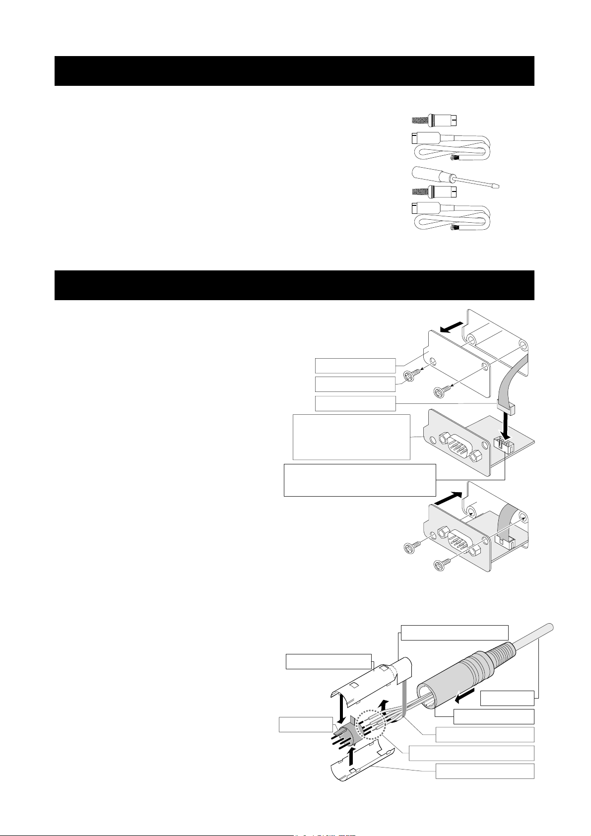
3. Packing List
GXA-03
GXA-04
GXA-06
...............
...............
...............
This manual 1
Mini DIN connector ( 8 pin, plug ) 1
Cable with connector ( AX-KO5692 ) 1
This manual 1
Screwdriver for adjustment 1
Mini DIN connector ( 4 pin, plug ) 1
Cable with connector ( AX-KO5692 ) 1
This manual 1
4. Installing the Option
Caution
Installing the option board to the balance
Step1
Step2
Disconnect the AC adaptor before installing the option to the balance.
Remove the two screws from the panel.
Pull gently the cable and option board
from the balance.
Peel off the connector that is affixed
to the panel with double-sided tape
and insert it into the socket of the
option board.
Option panel: Confirm
the layout of terminal,
etc. on the option.
Socket : Confirm the position
of the socket on the option.
Panel
Screws
Connector
Step3
Attach the option board to the balance.
Secure with the two screws removed in step 1.
Assembling the mini-DIN connector
You can use the GXA-04 ( AX-K0592 ) and GXA-06 ( AX-K0593 )
of the option cable assembled with the mini-DIN connector.
Step 1
Pass the cable through the rubber sleeve.
Step 2
Solder wires and terminal.
Step 3
Cover the terminal with the top
metal case and bottom metal case.
Step 4
Fasten wires with the top metal case.
Step 5
Insert the assembled parts into the
rubber sleeve.
3
Top metal case
Terminal
Part to secure wires
Cable
Rubber sleeve
Fasten wires tightl
Solder wires and terminal
Bottom metal case
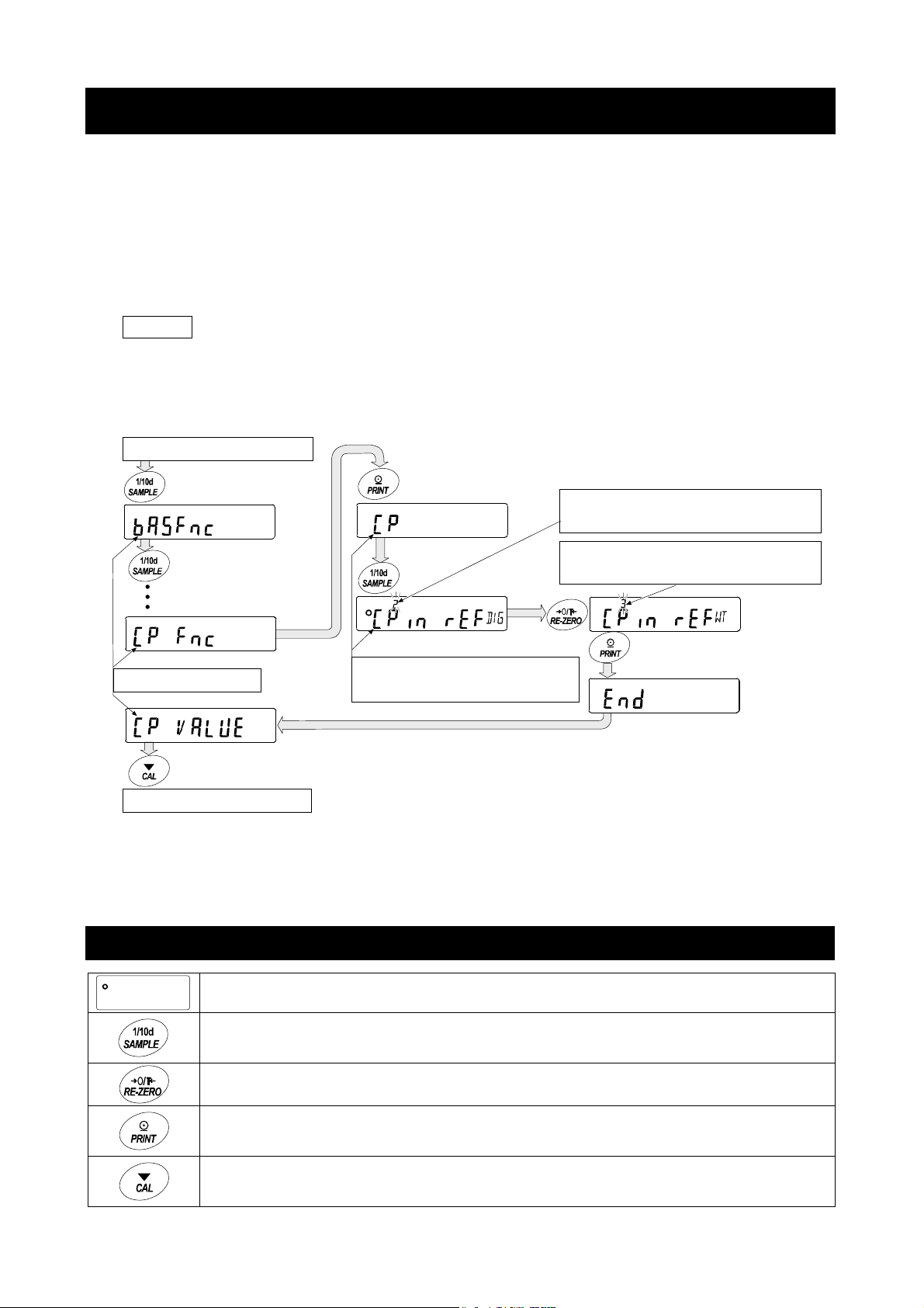
5. Function Table of Balance
The function table stores parameters that specify how to operate the balance, and it is used to
mointor or update those parameters. These parameters are stored in memory even if the AC
adaptor is removed and are retained until overwritten. Balance operations are specified by
this table when using the GXA-03, GXA-04 and GXA-06. The table menu consists of two
layers as shown in the diagram below. The first layer is the “Class” and the second layer is the
“Item”. Each item stores a "parameter". The last displayed parameter is in effect. After the
PRINT key is pressed, these updated parameters are applied to operations of the balance.
Example of settings and menu structure
Example : Set to "
Start from weighing mode
Caution
The balance may not function properly, depending on the settings and the operating
environment. Be sure to set parameters correctly.
Press and hold
Press several times
Class
Finish to weighing mode
Center value using sample weight input
Press several times
Press several times
Item
Input method
" of "
Input method
Parameter
Center value using numerical input
Parameter
Center value using sample weight
Press Press
" in "
Comparator
".
5.1. Operation Keys and Display of Function Table
The 〇 indicates that the parameter displayed is in effect.
Enters the function table when pressed and held in the weighing mode.
Selects the class or item in the function table.
Changes the parameter.
Moves to an item in the class when a class is displayed.
Stores the new parameter and displays the next class when an item is displayed.
Cancels new parameter and displays the next class when an item is displayed.
Exits the function table and returns to the weighing mode when a class is displayed.
4
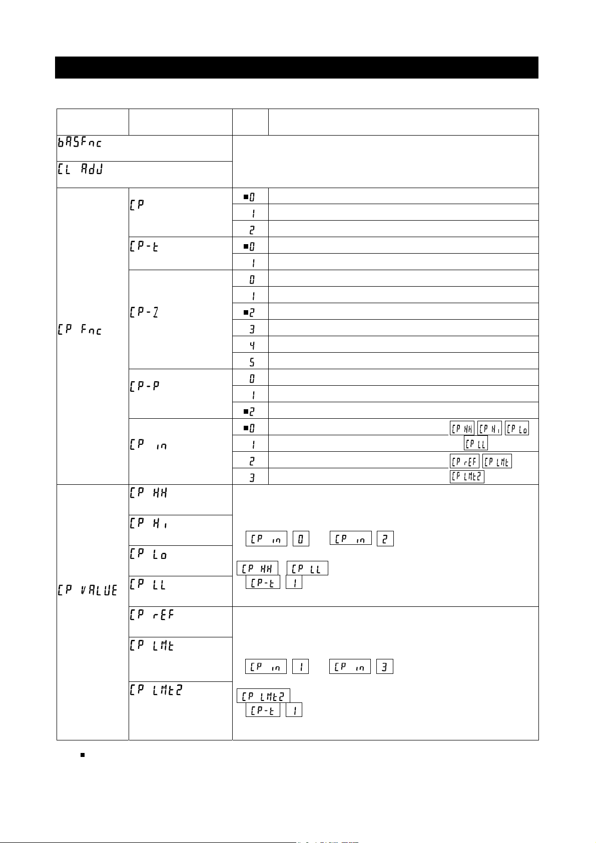
5.2. Items List of the Function Table
Note Functions available differ by model of the balance.
Class Item
Environment, display
Clock adjustment
Comparator
Comparator
threshold
value
Comparator mode
Comparison method
Near zero
Polarity
Input method
Second upper limit
Upper limit
Lower limit
Second lower limit
Center value
Tolerance range
from center value
Second tolerance
range from center
value
Param
eter
( Refer to the instruction manual of main unit )
No comparison (Comparator is not used)
Comparison when stable value or overloaded
Comparison always
3-stage comparison HI, OK, LO
5-stage comparison HH, HI, OK, LO, LL
Comparison including near zero
Comparison excluding ±5 digits (counts) from zero
Comparison excluding ±10 digits (counts) from zero
Comparison excluding ±20 digits (counts) from zero
Comparison excluding ±50 digits (counts) from zero
Comparison excluding ±100 digits (counts) from zero
Comparison of positive values only
Comparison of negative values only
Comparison of both polarities
Threshold value using numerical input
Threshold value using sample weight
Center value using numerical input
Center value using sample weight
Refer to explanation of "7. GXA-04 Comparator output".
Input number when numerical input
(
( ) is selected.
Refer to explanation of "7. GXA-04 Comparator output".
Input sample weight when sample weight input
(
( ) is selected.
or ) is selected.
,
or
is displayed when 5-stage comparison
are displayed when 5-stage comparison
Description
, ,
and are used
) is selected.
, and
are used
indicates factory settings. Digit is the unit of minimum division (minimum weighing value).
5
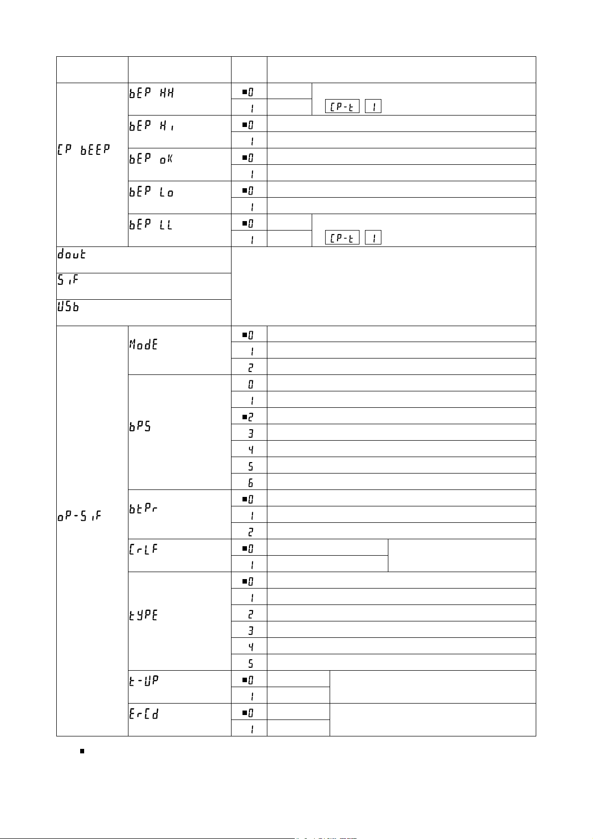
Class Item
HH buzzer
Hi buzzer
Comparator
buzzer
Data output
Serial interface
USB interface
Option serial
interface
OK buzzer
Lo buzzer
LL buzzer
Connection
Baud rate
Data bit, parity bit
Te r m in a t or
Data format
Timeout
AK, Error code
Param
eter
Off
On
Off
On
Off
On
Off
On
Off
On
( Refer to instruction manual of main unit )
Computer
Printer
External display
600 bps
1200 bps
2400 bps
4800 bps
9600 bps
19200 bps
38400 bps
7 bits, Even
7 bits, Odd
8 bits, None
CR LF CR: ASCII code 0Dh
Do not use LF: ASCII code 0Ah
A&D standard format
DP format
KF format
MT format
NU format
CSV format
No limit
1 second
No output
Output
Displayed only when 5-stage comparison
( ) is selected.
Displayed only when 5-stage comparison
( ) is selected.
Select wait time to receive a command
AK: ASCII code 06h
Description
indicates factory settings.
6
 Loading...