

Page 1
GXA-03 RS-232C Isolated Interface
GXA-04 Comparator output
GXA-06 Analog voltage output
1WMPD4003498
Page 2

© 2017 A&D Company, Limited. All rights reserved.
No part of this publication may be reproduced, transmitted, transcribed, or translated
into any language in any form by any means without the written permission of A&D
Company, Limited.
The contents of this manual and the specifications of the instrument covered by this
manual are subject to change for improvement without any notice and obligation on
the part of the manufacturer.
Page 3

Contents
1. Introduction...................................................................................................................................2
2. Features ....................................................................................................................................... 2
3. Packing List..................................................................................................................................3
4. Installing the Option ..................................................................................................................... 3
5. Function Table of Balance........................................................................................................... 4
5.1. Operation Keys and Display of Function Table................................................................... 4
5.2. Items List of the Function Table ........................................................................................... 5
6. GXA-03 Isolated RS-232C interface.......................................................................................... 8
6.1. Specifications of Serial Interface..........................................................................................8
7. GXA-04 Comparator Output.......................................................................................................9
7.1. Specifications of Comparator Output................................................................................... 9
7.2. Using the Comparator Output............................................................................................10
7.3. Comparison Method Selection
7.4. Setting Threshold Values ................................................................................................... 12
7.5. Setting Center Value and Tolerance Range......................................................................13
8. GXA-06 Analog Voltage Output................................................................................................15
8.1. Specifications of Analog Voltage Output............................................................................15
8.2. Function Table of Analog Voltage Output..........................................................................16
8.3. Voltage Output Selection....................................................................................................18
8.4. Voltage Output Fine Adjustment ........................................................................................ 18
8.5. Fixed Voltage Output ........................................................................................................19
(Tolerance Range and Center Value or Threshold Values)
.............. 11
Page 4
1. Introduction
This manual describes options for the GX-A series and GF-A series and how to get the most
out of them in terms of performance. Read this manual thoroughly before using the options
and keep it at hand for future reference.
2. Features
The following options can be used for the GX-A series and GF-A series.
GXA-03 Isolated RS-232C interface
GXA-04 Comparator output (with buzzer) / External contact input x 2
GXA-06 Analog voltage output
GXA-03: Isolated RS-232C interface
Commands from the PLC or other devices installed in the factory environment can be used to
make the following operations : output measurement data from the balance, input parameters
into the balance, control the balance, reference parameters of the balance, etc.
The RS-232C is equipped with a data format to manage the balance in accordance with GLP.
( Refer to the instruction manual of the balance. )
GXA-04: Comparator output / External contact input
The GXA-04 can compare the weighing value and preset threshold values and can output
the result to the contact output.
The GXA-04 is equipped with six contact outputs: "HH", "HI", "OK", "LO", "LL" of the
comparison output and "READY" output to indicate the status of the balance.
3-stage comparison or 5-stage comparison can be selected.
The GXA-04 can sound a buzzer according to the comparison result.
The GXA-04 is equipped with external control input terminals that can make the RE-ZERO
and PRINT key operations. An optional foot switch (AX-SW137-PRINT,
AX-SW137-RE-ZERO ) can be used.
GXA-06: Analog voltage output
The GXA-06 can output analog voltage in the following modes :
"mode where the specified digits of the weighing value are converted to voltage" and
"mode where weighing value is converted to voltage in range between gross zero or net zero
and full scale".
The voltage output range can be selected using the "0V /0.2V " switch on the panel.
It can be selected "0 to 1V" range and "0.2V to 1V" range. The factory setting is "0 to 1V" range.
2
Page 5
y
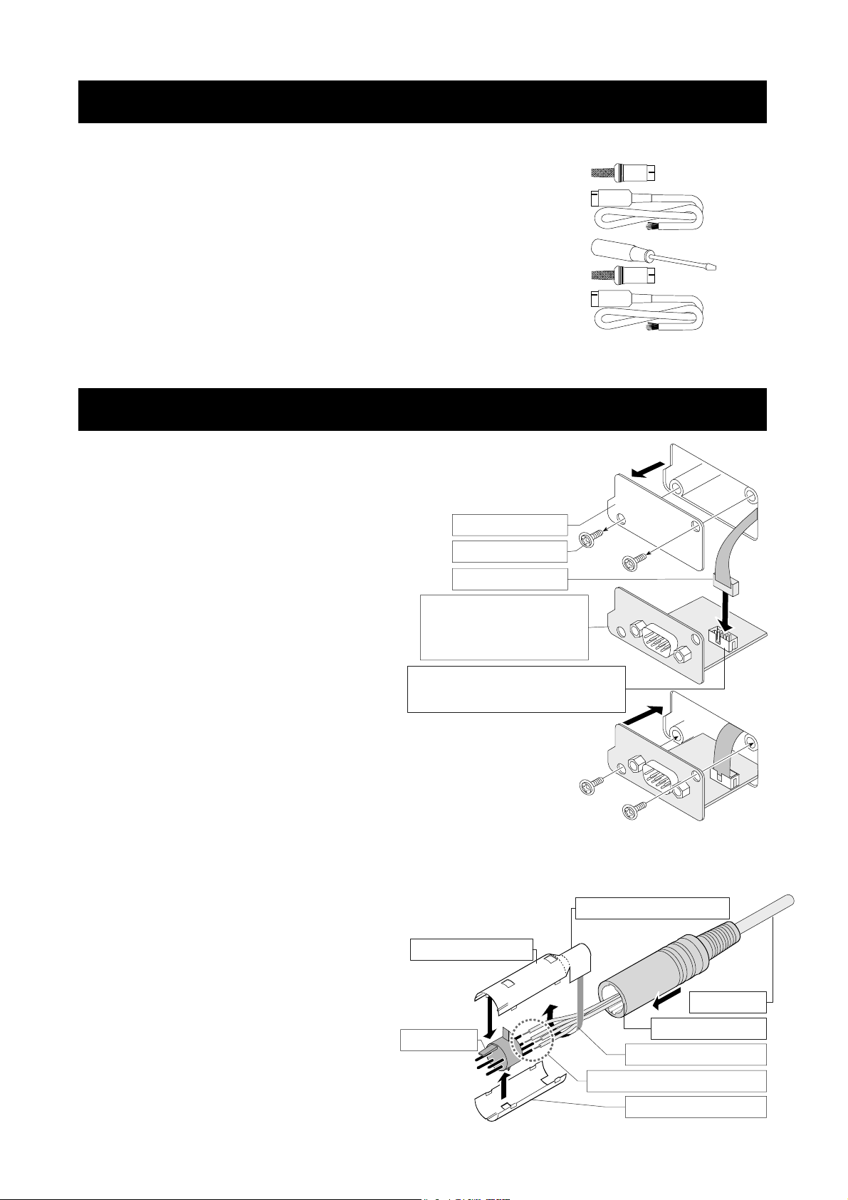
3. Packing List
GXA-03
GXA-04
GXA-06
...............
...............
...............
This manual 1
Mini DIN connector ( 8 pin, plug ) 1
Cable with connector ( AX-KO5692 ) 1
This manual 1
Screwdriver for adjustment 1
Mini DIN connector ( 4 pin, plug ) 1
Cable with connector ( AX-KO5692 ) 1
This manual 1
4. Installing the Option
Caution
Installing the option board to the balance
Step1
Step2
Disconnect the AC adaptor before installing the option to the balance.
Remove the two screws from the panel.
Pull gently the cable and option board
from the balance.
Peel off the connector that is affixed
to the panel with double-sided tape
and insert it into the socket of the
option board.
Option panel: Confirm
the layout of terminal,
etc. on the option.
Socket : Confirm the position
of the socket on the option.
Panel
Screws
Connector
Step3
Attach the option board to the balance.
Secure with the two screws removed in step 1.
Assembling the mini-DIN connector
You can use the GXA-04 ( AX-K0592 ) and GXA-06 ( AX-K0593 )
of the option cable assembled with the mini-DIN connector.
Step 1
Pass the cable through the rubber sleeve.
Step 2
Solder wires and terminal.
Step 3
Cover the terminal with the top
metal case and bottom metal case.
Step 4
Fasten wires with the top metal case.
Step 5
Insert the assembled parts into the
rubber sleeve.
3
Top metal case
Terminal
Part to secure wires
Cable
Rubber sleeve
Fasten wires tightl
Solder wires and terminal
Bottom metal case
Page 6
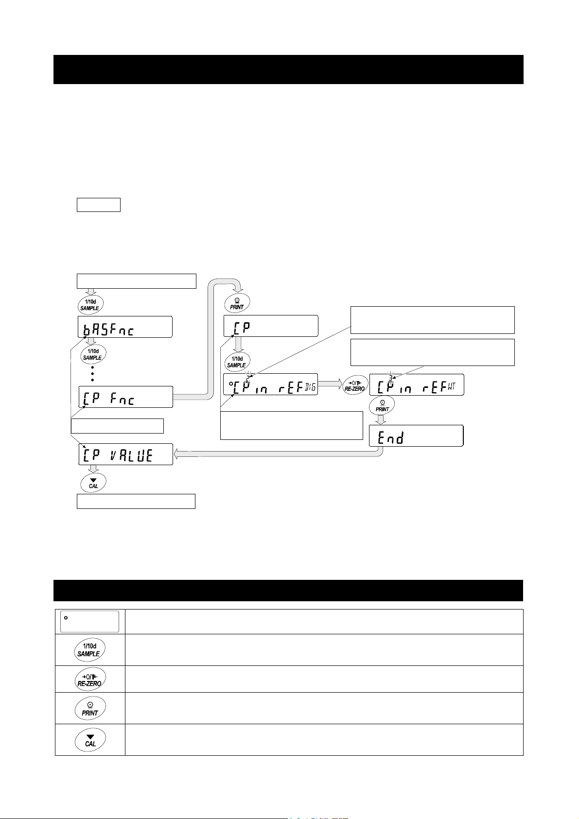
5. Function Table of Balance
The function table stores parameters that specify how to operate the balance, and it is used to
mointor or update those parameters. These parameters are stored in memory even if the AC
adaptor is removed and are retained until overwritten. Balance operations are specified by
this table when using the GXA-03, GXA-04 and GXA-06. The table menu consists of two
layers as shown in the diagram below. The first layer is the “Class” and the second layer is the
“Item”. Each item stores a "parameter". The last displayed parameter is in effect. After the
PRINT key is pressed, these updated parameters are applied to operations of the balance.
Example of settings and menu structure
Example : Set to "
Start from weighing mode
Caution
The balance may not function properly, depending on the settings and the operating
environment. Be sure to set parameters correctly.
Press and hold
Press several times
Class
Finish to weighing mode
Center value using sample weight input
Press several times
Press several times
Item
Input method
" of "
Input method
Parameter
Center value using numerical input
Parameter
Center value using sample weight
Press Press
" in "
Comparator
".
5.1. Operation Keys and Display of Function Table
The 〇 indicates that the parameter displayed is in effect.
Enters the function table when pressed and held in the weighing mode.
Selects the class or item in the function table.
Changes the parameter.
Moves to an item in the class when a class is displayed.
Stores the new parameter and displays the next class when an item is displayed.
Cancels new parameter and displays the next class when an item is displayed.
Exits the function table and returns to the weighing mode when a class is displayed.
4
Page 7
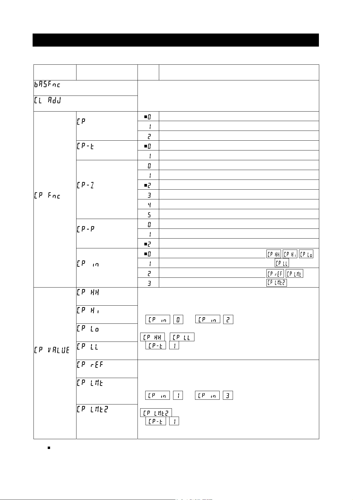
5.2. Items List of the Function Table
Note Functions available differ by model of the balance.
Class Item
Environment, display
Clock adjustment
Comparator
Comparator
threshold
value
Comparator mode
Comparison method
Near zero
Polarity
Input method
Second upper limit
Upper limit
Lower limit
Second lower limit
Center value
Tolerance range
from center value
Second tolerance
range from center
value
Param
eter
( Refer to the instruction manual of main unit )
No comparison (Comparator is not used)
Comparison when stable value or overloaded
Comparison always
3-stage comparison HI, OK, LO
5-stage comparison HH, HI, OK, LO, LL
Comparison including near zero
Comparison excluding ±5 digits (counts) from zero
Comparison excluding ±10 digits (counts) from zero
Comparison excluding ±20 digits (counts) from zero
Comparison excluding ±50 digits (counts) from zero
Comparison excluding ±100 digits (counts) from zero
Comparison of positive values only
Comparison of negative values only
Comparison of both polarities
Threshold value using numerical input
Threshold value using sample weight
Center value using numerical input
Center value using sample weight
Refer to explanation of "7. GXA-04 Comparator output".
Input number when numerical input
(
( ) is selected.
Refer to explanation of "7. GXA-04 Comparator output".
Input sample weight when sample weight input
(
( ) is selected.
or ) is selected.
,
or
is displayed when 5-stage comparison
are displayed when 5-stage comparison
Description
, ,
and are used
) is selected.
, and
are used
indicates factory settings. Digit is the unit of minimum division (minimum weighing value).
5
Page 8
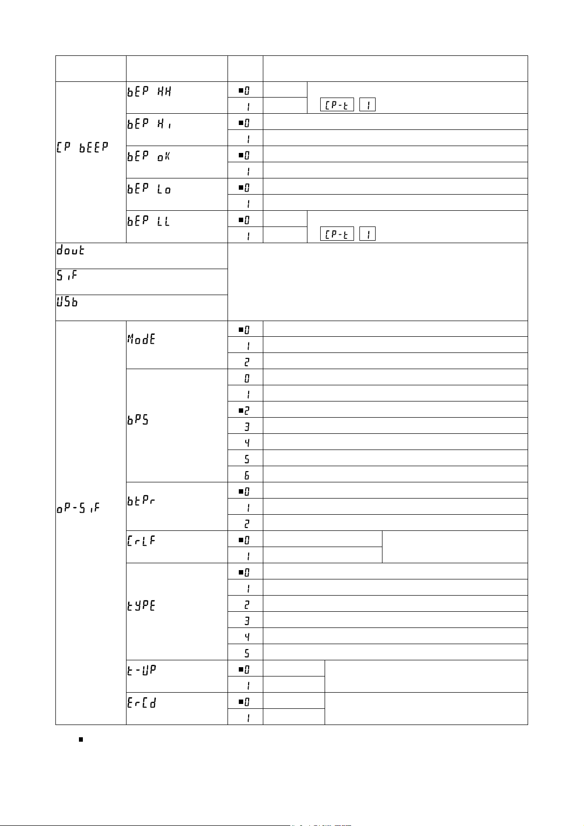
Class Item
HH buzzer
Hi buzzer
Comparator
buzzer
Data output
Serial interface
USB interface
Option serial
interface
OK buzzer
Lo buzzer
LL buzzer
Connection
Baud rate
Data bit, parity bit
Te r m in a t or
Data format
Timeout
AK, Error code
Param
eter
Off
On
Off
On
Off
On
Off
On
Off
On
( Refer to instruction manual of main unit )
Computer
Printer
External display
600 bps
1200 bps
2400 bps
4800 bps
9600 bps
19200 bps
38400 bps
7 bits, Even
7 bits, Odd
8 bits, None
CR LF CR: ASCII code 0Dh
Do not use LF: ASCII code 0Ah
A&D standard format
DP format
KF format
MT format
NU format
CSV format
No limit
1 second
No output
Output
Displayed only when 5-stage comparison
( ) is selected.
Displayed only when 5-stage comparison
( ) is selected.
Select wait time to receive a command
AK: ASCII code 06h
Description
indicates factory settings.
6
Page 9

Class Item
Analog output mode
Analog output
Output digit
selection
Application
Alarm function for minimum
weighing value
Unit
Density function
ID number
Password lock
Automatic calibration
Internal mass value correction
#
#
Param
eter
2-digit output mode
3-digit output mode
Net full scale output mode
Gross full scale output mode
First digit
Second digit
Third digit
4th digit
5th digit
6th digit
7th digit
( Refer to instruction manual of main unit )
( Refer to instruction manual of main unit )
Description
Displayed only when
the GXA-06 is
connected.
Displayed only when
the GXA-06 is
connected.
indicates factory settings.
7
# : Settings for GX-A ser ies.
Page 10

6. GXA-03 Isolated RS-232C interface
This isolated RS-232C interface is used to communicate with peripherals.
Connect the AC adaptor to this option (GXA-03) when AD-8529R-W or AD-8529PC-W is used.
Refer to the instruction manual of main unit concerning function of RS-232C
6.1. Specifications of Serial Interface
This interface is DCE. Use straight cable to connect to a computer ( DTE ).
Transmission system EIA RS-232C
Transmission Asynchronous, bi-directional, half-duplex
Data format Baud rate: 600, 1200, 2400, 4800, 9600, 19200, 38400 bps
Data bits: 7 bits or 8 bits
Parity bit: Even, Odd (Data length 7 bits)
None (Data length 8 bits)
Stop bit: 1 bit
Code: ASCII
Connector D-Sub9 pin [male]
RS-232C
-5 V to -15 V
+5 V to +15 V
Data bits Stop bit
Start bit Parity bit
Pin assignments
Pin No. Signal Direction Description
1 - N.C. No connection
2 RXD Output Transmit data
3 TXD Input Receive data
4 - N.C. No connection
5 SG Signal ground
6 DSR Output Data set ready
7 RTS Input Request to send
8 CTS Output Clear to send
9 - N.C. No connection
Signal names are those of the DTE side.
Balance (DCE) Computer (DTE)
Inside balance Terminal example
Straight cable
Inch screw
#4-40UNC
Approx. 5 V
8
Page 11

7. GXA-04 Comparator Output
The comparator output (GXA-04) has the function to compare between the weighing value
and preset second upper limit, upper limit, lower limit or second lower limit. The result of
comparison can be output to the contact. When the contact is shorted, this option can select
whether or not to sound the buzzer.
Optional foot switch ( AX-SW137-PRINT, AX-SW137-RE-ZERO ) or other external switches
can be used.
7.1. Specifications of Comparator Output
Maximum contact voltage: 50 V DC
Maximum contact current: 100 mA DC
Maximum contact resistance: 20 Ω
Output connector Compatible plug : 8 pin mini DIN connector [Female](Accessory)
E8-200J-100 or equivalent
External contact input connector Compatible plug : φ3.5 mm 3 pole mini stereo jack
MP-013LC or equivalent parts
Panel External View
8 7 6 3 Comparator output connector
4 External contact input x2
5 2 3 1
2
1 Example of contact input terminal
Comparator output circuit Pin assignments and wire colors of
accessory cable
External contact input circuit
Pin No. Description Wire color
1 READY Output Red
2 LL Output White
3 LO Output Black
4 N.C. No connection Yellow
5 OK Output Blue
6 HI Output Green
7 HH Output Brown
8 COM Gray
Housing Case Shield
Pin No. Description
1 GND
2 RE-ZERO External contact input
3 PRINT External contact input
Optional foot switch can connect to either input.
9
Page 12

Using External Contact Input
When 1 pin and 3 pin or 1 pin and 2 pin of lead wire of optional foot switch
( AX-SW137-PRINT, AX-SW137-RE-ZERO ) is shorted 100 ms or longer, it can be
operated the same as the PRINT key and RE-ZERO key on the panel.
7.2. Using the Comparator Output
This option can output results of the 3-stage comparison or 5-stage comparison that is
specified at "Comparison method (
Comparison results are displayed using HI , OK , LO and are output using contacts of
I/O terminals. Comparison tolerance ranges are the following 3 types and they can be
specified at "Comparator mode (
"No comparison", "Comparison when stable value or overloaded", or "Comparison always"
The range of near zero can is specified at "Near zero (
There are two types of comparison method. One is the method using second upper limit,
upper limit, lower limit and second lower limit. Another is the method using center value and
tolerance range. There two types of input methods for second upper limit, upper limit, lower
limit and second lower limit. One is the numerical input. Another is the input using sample
weight. Balance can sound a buzzer according to the comparison result. That can be
specified at "Comparator buzzer (
When weighing value is not displayed in performing RE-ZERO, etc., READY contact
becomes "open". When weighing value is displayed, READY contact becomes "short".
)" in the function table of the balance.
)" in the function table.
)" in the function table.
)" in the function table.
3-stage comparison result 3-stage comparison - display, contact output
Weighing value Contact output
Threshold value Formula
UL < WV HI
UL
LL ≦ WV ≦ UL OK
LL
WV < LL LO
Weighing value: WV, Upper limit: UL, Lower limit: LL
Result Display
HI illuminated
OK illuminated
LO illuminated
HI OK LO
Buzzer
Short Open
Short
Open Short
5-stage comparison result 5-stage comparison - display, contact output
Weighing value Contact output
Threshold value Formula
SUL
SLL
10
SUL < WV HH
UL < WV ≦ SUL HI
UL
LL ≦ WV ≦ UL OK
LL
SLL ≦ WV < LL LO
WV < SLL LL
Weighing value: WV, Second upper limit: SUL, Upper limit: UL, Lower limit: LL, Second lower limit: SLL
Result Display
HI blinking
HI illuminated
OK illuminated
LO illuminated
LO blinking
HH HI OK LO LL
Buzzer
Short
Short Open
Short
Open Short
Short
Page 13

7.3. Comparison Method Selection
(Tolerance Range and Center Value or Threshold Values)
Setting Example
Comparison always ......................................................................
5-stage comparison
Comparison excluding ±5 digits (counts) from zero ...................
Comparison of both polarities ......................................................
Center value using numerical input
Center value using sample weight
......................................................................
...................................................
....................................................
Procedure
Step
1 Press and hold the SAMPLE key to enter the function table.
Step
2 Press the SAMPLE key to display
Step
3 Press the PRINT key to enter
Step
4 Press the RE-ZERO key several times to display
(Comparison always).
is displayed.
(Comparator).
(Comparator).
Factory setting
or
Step
5 Press the SAMPLE key to display
method).
Step
6 Press the RE-ZERO key to display
comparison).
Step
7 Press the SAMPLE key to display
Step
8 Press the RE-ZERO key several times to display
(Comparison excluding ±5 digits (counts) from zero).
Step
9 Press the SAMPLE key several times to display
(Input method).
Step
10 Press the RE-ZERO key several times to select input method.
Step
11 Press the PRINT key to store new settings and use them.
(
Center value using numerical input
(
Center value using sample weight
(Comparison
(5-stage
(Near zero).
) or,
)
or
11
Page 14

7.4. Setting Threshold Values
This explanation uses (5-stage comparison) and specifies
(Threshold value using numerical input) or
weight) to
(input method) in the function table and inputs the threshold value.
(Threshold value using sample
Selecting a input method (If or )
Step
1 Press and hold the SAMPLE key to enter the function table.
Step
2 Press the SAMPLE key several times to display
Step
3 Press the PRINT key to enter
Step
4 Press the SAMPLE key several times to input threshold value. Refer to the following
"Threshold value using numerical input" or "Threshold value using sample weight".
Step
5 If the PRINT key is pressed when threshold value is displayed, the current parameters
are displayed ( all digits blinks ).
(Comparator threshold value).
(Comparator threshold value).
Numerical input of threshold values (If
Step
6 If changing the parameters, press the RE-ZERO key to store the following keys.
is displayed.
)
SAMPLE key Moves blinking digit.
RE-ZERO key Changes value of blinking digit.
MODE key Changes polarity.
PRINT key Stores and proceeds to step 7.
CAL key Cancels and proceeds to step 7.
If the current parameters will be maintained, press the PRINT or CAL key to
proceed to step 7.
Step
7 Repeat step 4, 5 and 6 for other threshold values.
Storing threshold values using sample weight (If
Step
8 Press the RE-ZERO key to display 0.00 g .
Put the sample on the weighing pan and press the PRINT key to store weighing value
as the threshold value.
RE-ZERO key Resets display of the balance to zero .
)
PRINT key Stores weighing value and proceeds to step 9.
Step
9 Repeat step 4, 5 and 6 for other threshold values.
12
Page 15

Storing threshold values using RS-232C commands from peripherals
The second upper limit, upper limit, lower limit and second lower limit can be specified using
#
RS-232C commands from peripherals.
Example command HH: +1000.000 g second upper limit
HI: +0800.000 g upper limit
LO: +0600.000 g lower limit
LL: +0400.000 g second lower limit
: space of ASCII code 20 h
7.5. Setting Center Value and Tolerance Range
This explanation uses (5-stage comparison), specifies
(Center value using numerical input) or
weight input) to
center value and numerical input of tolerance range.
(input method) in the function table, and compares using the
(Center value using sample
Selecting a input method (If or )
Step
1 Press and hold the SAMPLE key to enter the function table.
Step
2 Press the SAMPLE key several times to display
value).
Step
3 Press the PRINT key to display
Step
4 Press the SAMPLE key several times to display "
"
Center value using sample weight
tolerance range.
is displayed.
(comparator threshold
(comparator threshold value).
Center value using numerical input
". Specify the center value, tolerance range and second
" or
Numerical input of center value (If )
Step
5 Press the PRINT key while displaying
digits blinking). If parameter does not need to be changed, press the PRINT key or CAL
key and proceed to step 6. If the parameter is to be changed, press the RE-ZERO key and
change it using the following keys.
SAMPLE key Moves blinking digit.
RE-ZERO key Changes value of blinking digit.
MODE key Changes polarity.
PRINT key Stores and proceeds to step 6.
CAL key Cancels and proceeds to step 6.
Step
6 Proceed to "Storing tolerance range from center value using numerical input".
13
.
The current parameter is displayed (all
Page 16

Storing center value using sample weight (If
Step
7 Press the PRINT key while displaying
(all digits blinks). Press the RE-ZERO key to enter to the sample weight input mode.
Press the RE-ZERO key to display 0.00 g . Put sample of center value on the pan
and press the PRINT key. The current parameter can be confirmed (all digits blinking).
Press the PRINT key to store the center value.
Step
8 Next,
Step
9 Proceed to "Storing tolerance range from center value using numerical input".
is displayed.
.
The current parameter is displayed
Storing tolerance range from center value using numerical input
Step
10 Press the PRINT key while displaying
If the tolerance range is to be changed, change it using the following keys.
Input the tolerance range with center value assumed to be 100 %.
SAMPLE key Moves blinking digit.
RE-ZERO key Changes value of blinking digit.
.
The current parameter is displayed.
)
PRINT key Stores and proceeds to step 11.
CAL key Cancels and proceeds to step 11.
Step
11 Press the PRINT key while displaying
If the second tolerance range is to be changed, change it using the following keys.
Input the second tolerance range with center value assumed to be 100 %.
SAMPLE key Moves blinking digit.
RE-ZERO key Changes value of blinking digit.
PRINT key Stores and proceeds to step 12.
CAL key Cancels and proceeds to step 12.
Step
12 Press the CAL key to return to weighing mode.
.
The current parameter is displayed.
14
Page 17

A
8. GXA-06 Analog Voltage Output
The analog voltage output (GXA-04) can convert the specified weighing value to analog
voltage between 0 and 1 V and output it.
8.1. Specifications of Analog Voltage Output
Analog Voltage Output
Output impedance 100 or less
Linearity ±0.3 % or less
Output connector Compatible plug: 4 pin mini DIN connector [Female](Accessory)
E4-200J-100 or equivalent
Pin connections Output 4 pin
GND 3 pin
Output range 0 V to 1 V With the slide switch set to "0V "
0.2 V to 1 V With the slide switch set to "0.2V "
Input impedance of 10 k or greater
the device connected
Panel External View
Analog output connector 3 Analog GND Slide switch: Output range
4 Analog voltage output Zero volume for fine adjustment
Span volume for fine adjustment
2
1
Pin assignments and
Output circuit wire colors of accessory cable
nalog voltage output
Pin No. Description Wire color
1 N.C. No connection Black
2 N.C. No connection Blue
3 Analog GND (0 V) Red
4 Analog voltage output White
Housing Case Shield
15
Page 18

8.2. Function Table of Analog Voltage Output
of the function table can be selected when this option is connected.
Analog output
Item Parameter Description
2-digit output mode Converts 2 consecutive digits with minimum digit
selected by
3-digit output mode Converts 3 consecutive digits with minimum digit
selected by
Net full scale output mode
Outputs 0.000 V when the net weight is zero.
Outputs 1.000 V when the net weight is full scale.
Output is 0.000 V when zero is set using the RE-ZERO key.
Gross full scale output mode
Outputs 0.000 V when the gross weight is zero.
Outputs 1.000 V when the gross weight is full scale.
Tare operation using the RE-ZERO key will not affect the output.
(Note: If tare is extremely light, tare operation might change the zero
point. Thus affecting the output.)
Analog
output mode
to voltage.
to voltage.
Output digit
selection
indicates factory settings.
Specify minimum digit to be output at
When is set to or , the setting is in effect.
Specify first digit as minimum digits.
Specify second digit as minimum digits.
Specify third digit as minimum digits.
Specify 4th digit as minimum digits.
Specify 5th digit as minimum digits.
Specify 6th digit as minimum digits.
Specify 7th digit as minimum digits.
mode.
Example
If Analog voltage output ( 0 V to 1 V )
0.67 V
0.56 V
0.45 V
0.34 V
0.23 V
0.12 V
0.01 V
.
Caution The hidden high-order digits are regarded as zero.
The hidden least significant digit is regarded as zero (when the least significant digit is
hidden using the SAMPLE key).
16
Page 19

If Analog voltage output ( 0 V to 1 V )
0.567 V
0.456 V
0.345 V
0.234 V
0.123 V
0.012 V
0.001 V
.
If
Model Full scale Model Full scale
GX-203A 220 g GF-203A 220 g
GX-303A 320 g GF-303A 320 g
GX-403A 420 g GF-403A 420 g
GX-603A 620 g GF-603A 620 g
GX-1003A 1100 g GF-1003A 1100 g
GX-1603A 1620 g GF-1603A 1620 g
GX-2002A 2200 g GF-2002A 2200 g
GX-3002A 3200 g GF-3002A 3200 g
GX-4002A 4200 g GF-4002A 4200 g
GX-6002A 6200 g GF-6002A 6200 g
GX-6001A 6200 g GF-6001A 6200 g
GX-10001A 10200 g GF-10001A 10200 g
Example When the GX-2002A displays 200 g, the voltage output of
or
( Using "0V " of the slide switch )
is 0.1 V.
1.000 V × = 0.100 V
Caution "Full scale" of the full scale output mode indicates the full scale values shown in the
tables above. The output voltage may exceed 1.000 V, depending on the weighing value.
Example When the GX-2002A displays 2200 g, the voltage output is 1.1 V.
( Using "0V " of the slide switch )
1.000 V × = 1.100 V
17
200 g
2000 g
2200 g
2000 g
Page 20

8.3. Voltage Output Selection
The range of output voltage can be change using the slide switch on the panel.
Factory settings is "0V ".
"0V " (0 to 1 V) : Zero 0.000 V, full scale 1.000 V
"0.2V " (0.2 to 1 V) : Zero 0.200 V, full scale 1.000 V
Panel External View
Analog output connector 3 Analog GND Slide switch: Output range
4 Analog voltage output Zero volume for fine adjustment
Span volume for fine adjustment
2
1
8.4. Voltage Output Fine Adjustment
The voltage output has been adjusted at the
factory before shipment.
Using the ZERO volume and SPAN for fine
adjustment and a voltmeter, voltage output can
be finely adjusted.
Procedure
Step
1 Turn off the display using the ON:OFF key.
Voltage output becomes zero point status.
Adjust the ZERO volume so that the voltmeter indicates
0.000 V ( when the slide switch is set to "0V ").
Adjust the ZERO volume so that the voltmeter indicates
0.200 V ( when the slide switch is set to "0.2V ").
Step
2 While pressing and holding the PRINT and
0V~/ 0. 2V~
The display to output 0 V ( 0.2 V).
The display to output 1 V.
ZERO SPAN
SAMPLE keys, press the ON:OFF key to enter
the initializing mode. Then 1 V is output. Adjust the SPAN
volume so that the voltmeter indicates 1.000 V
Step
3 Repeat step 1 and step 2 until the correct voltage output
is obtained.
18
Page 21

8.5. Fixed Voltage Output
The voltage output is fixed under the following conditions:
With the display off, 0 V is output ( or 0.2 V if the slide switch is set to "0.2V ") when not
weighing during calibration, etc..
During the re-zeroing operation in gross full scale output mode (
the previous output value is retained.
During the re-zeroing operation in 2-digit output mode (
0 V is output ( or 0.2 V if the slide switch is set to "0.2V ").
During the re-zeroing operation in 3-digit output mode (
0 V is output ( or 0.2 V if the slide switch is set to "0.2V ").
During the re-zeroing operation in Net full scale output mode (
0 V is output ( or 0.2 V if the slide switch is set to "0.2V ").
When -E (weighing value is negative overload) is displayed,
0 V is output ( or 0.2 V if the slide switch is set to "0.2V ").
When E (weighing value is positive overload) is displayed,
the following voltages are output.
),
),
),
),
Example
GX-203A 1.000 V 1.100 V GF-203A 1.000 V 1.100 V
GX-303A 1.000 V 1.067 V GF-303A 1.000 V 1.067 V
GX-403A 1.000 V 1.050 V GF-403A 1.000 V 1.050 V
GX-603A 1.000 V 1.033 V GF-603A 1.000 V 1.033 V
GX-1003A 1.000 V 1.100 V GF-1003A 1.000 V 1.100 V
GX-1603A 1.000 V 1.013 V GF-1603A 1.000 V 1.013 V
GX-2002A 1.000 V 1.100 V GF-2002A 1.000 V 1.100 V
GX-3002A 1.000 V 1.067 V GF-3002A 1.000 V 1.067 V
GX-4002A 1.000 V 1.050 V GF-4002A 1.000 V 1.050 V
GX-6002A 1.000 V 1.033 V GF-6002A 1.000 V 1.033 V
GX-6001A 1.000 V 1.033 V GF-6001A 1.000 V 1.033 V
GX-10001A 1.000 V 1.020 V GF-10001A 1.000 V 1.020 V
Voltage output when E is displayed if the slide switch is set to "0V ".
Model
.,
.
.,
Model
.
.,
.,
.
.
19
Page 22

MEMO
20
Page 23

Page 24

3-23-14 Higashi-Ikebukuro, Toshima-ku, Tokyo 170-0013, JAPAN
Telephone: [81] (3) 5391-6132 Fax: [81] (3) 5391-6148
A&D ENGINEERING, INC.
1756 Automation Parkway, San Jose, California 95131, U.S.A.
Telephone: [1] (408) 263-5333 Fax: [1] (408)263-0119
A&D INSTRUMENTS LIMITED
Unit 24/26 Blacklands Way, Abingdon Business Park, Abingdon, Oxfordshire OX14 1DY United Kingdom
Telephone: [44] (1235) 550420 Fax: [44] (1235) 550485
A&D AUSTRALASIA PTY LTD
32 Dew Street, Thebarton, South Australia 5031, AUSTRALIA
Telephone: [61] (8) 8301-8100 Fax: [61] (8) 8352-7409
A&D KOREA Limited 한국에이.엔.디(주)
서울특별시 영등포구 국제금융로6길33 (여의도동) 맨하탄빌딩 817 우편 번호 150-749
( 817, Manhattan Bldg., 33. Gukjegeumyung-ro 6-gil, Yeongdeungpo-gu, Seoul, 150-749 Korea )
전화: [82] (2) 780-4101 팩스: [82] (2) 782-4280
OOO A&D RUS OOO "ЭЙ энд ДИ РУС"
121357, Российская Федерация, г.Москва, ул. Верейская, дом 17
( Business-Center "Vereyskaya Plaza-2" 121357, Russian Federation, Moscow, Vereyskaya Street 17 )
тел.: [7] (495) 937-33-44 факс: [7] (495) 937-55-66
A&D INSTRUMENTS INDIA PRIVATE LIMITED
( 509, Udyog Vihar, Phase-
: 91-124-4715555
, Gurgaon - 122 016, Haryana, India )
: 91-124-4715599
 Loading...