

GX-A SERIES
GF-A SERIES
ulti-Function Balance
M
INSTRUCTION MANUAL
GX-A series
GX-203A/GX-303A/GX-403A/GX-603A/GX-1003A/GX-1603A
GX-2002A/GX-3002A/GX-4002A/GX-6002A/GX-10002A
GX-6001A/GX-10001A
GF-A series
GF-203A/GF-303A/GF-403A/GF-603A/GF-1003A/GF-1603A
GF-2002A/GF-3002A/GF-4002A/GF-6002A/GF-10002A
GF-6001A/GF-10001A
1WMPD4003475

© 2017 A&D Company Ltd. All rights reserved.
No part of this publication may be reproduced, transmitted, transcribed, or translated
into any language in any form by any means without the written permission of A&D
Company Ltd.
The contents of this manual and the specifications of the instrument covered by this
manual are subject to change for improvement without notice.
Windows, Word and Excel are registered trademarks of the Microsoft Corporation.

Contents
1. Introduction ........................................................................................................................ 4
1-1 Features ....................................................................................................................................................... 4
1-2 About The Models ........................................................................................................................................ 5
1-3 Compliance .................................................................................................................................................. 5
2. Unpacking The Balance ..................................................................................................... 7
2-1 Installing The Balance .................................................................................................................................. 9
2-2 Precautions .................................................................................................................................................. 9
2-3 During Use ................................................................................................................................................. 10
2-4 After Use ..................................................................................................................................................... 11
2-5 Power Supply ............................................................................................................................................. 11
3. Display Symbols And Key Operation................................................................................ 12
4. Weighing Units ................................................................................................................. 14
4-1 Units ........................................................................................................................................................... 14
4-2 Storing Units ............................................................................................................................................... 17
5. Weighing .......................................................................................................................... 19
5-1 Basic Operation .......................................................................................................................................... 19
5-2 Counting Mode(PCS) ............................................................................................................................ 21
5-3 Percent Mode (%) ...................................................................................................................................... 23
5-4 Animal Weighing Mode(Hold Function) ................................................................................................. 24
6. Impact Detection Function ............................................................................................... 25
7. Response Adjustment / Self Check Function ................................................................... 26
7-1 Response Adjustment ................................................................................................................................ 26
7-2 Self-Check-Function / Automatic Setting Of Minimum Weight Value ..................................................... 27
8. Calibration ........................................................................................................................ 28
8-1 Automatic Self Calibration For The GX-A Series ......................................................................................... 29
8-2 One-Touch Calibration For The GX-A Series ............................................................................................. 30
8-3 Calibration Using An External Weight ........................................................................................................ 31
8-4 Calibration Test Using An External Weight ................................................................................................ 32
8-5 Correcting The Internal Mass Value Of The GX-A series .......................................................................... 33
8-6 Correcting The Internal Mass Value Of The GX-A series (Auto) .................................................................... 34
8-7 Correcting The Internal Mass Value Of The GX-A series (Manual) ....................................................................... 35
9. Function Switch And Initialization ..................................................................................... 36
9-1 Permit Or Inhibit ......................................................................................................................................... 36
1

9-2 Initializing The Balance .............................................................................................................................. 38
10. Function Table ................................................................................................................ 39
10-1 Setting The Function Table ...................................................................................................................... 39
10-2 Details Of The Function Table.................................................................................................................. 41
10-3 Description Of The Class "Environment, Display" ................................................................................... 48
10-4 Clock And Calendar Function .................................................................................................................. 50
10-5 Comparator Function ............................................................................................................................... 52
11. ID Number And GLP Report............................................................................................ 55
11-1 Setting The ID Number ............................................................................................................................ 55
11-2 GLP Report .............................................................................................................................................. 57
12. Data Memory .................................................................................................................. 60
12-1 Data Memory For Weighing Data ............................................................................................................ 60
12-2 Data Memory For Calibration And Calibration Test ................................................................................. 62
13. Statistical Calculation Mode ............................................................................................ 65
13-1 How To Use The Statistic Calculation ...................................................................................................... 65
13-2 Statistical Calculation Mode (Example Of Use) ....................................................................................... 70
14. Flow Measurement ......................................................................................................... 7 2
14-1 How To Use Flow Measurement .............................................................................................................. 73
14-2 Flow Measurement Setting ...................................................................................................................... 75
15. Gross Net Tare Function ................................................................................................. 77
15-1 Preparation Of Gross Net Tare Function ................................................................................................. 77
15-2 Example Of Using The Gross Net Tare Function .................................................................................... 78
16. Minimum Weighing Warning Function ............................................................................ 79
17. Underhook ...................................................................................................................... 81
18. Programmable-Unit ........................................................................................................ 8 2
19. Density Measurement ..................................................................................................... 83
20. Password Lock Function ................................................................................................. 88
20-1 Using Password Function ........................................................................................................................ 88
20-2 Changing Password ................................................................................................................................. 89
20-3 Inputting Password When Turning On The Balance ................................................................................ 91
20-4 Missing Password .................................................................................................................................... 91
21. Maintenance ................................................................................................................... 92
2

21-1 Treatment Of The Balance ....................................................................................................................... 92
22. Troubleshooting.............................................................................................................. 92
22-1 Checking The Balance Performance And Environment ........................................................................... 92
22-2 Error Codes .............................................................................................................................................. 94
22-3 Other Display ........................................................................................................................................... 97
22-4 Asking For Repair ..................................................................................................................................... 97
23. Specififations .................................................................................................................. 98
23-1 GX-A series 0.001g models ................................................................................................................... 98
23-2 GX-A series 0.01g models ..................................................................................................................... 99
23-3 GX-A series 0.1g models ..................................................................................................................... 100
23-4 GF-A series 0.001g models ................................................................................................................. 101
23-5 GF-A series 0.01g models...................................................................................................................... 102
23-6 GF-A series 0.1g models ..................................................................................................................... 103
24. External Dimention ....................................................................................................... 104
24-1 Options And Perpheral Instruments ....................................................................................................... 106
3

1. Introduction
This manual describes how the GX-A/GF-A series balance works and how to get the most out of it in
terms of performance. Read this manual thoroughly before using the balance and keep it at hand for
future reference.
This manual consists of the following five parts:
Basic operation ................................. Describes precautions on handling the balance, balance
construction and basic balance operation.
Adapting to the environment ·········· Describes response adjustment, calibration and calibration test.
Functions ........................................... Describes various functions of the balance.
Interface ···································· Describes the interface which transmits data and controls the
balance. To use it, need a personal computer or an optional
printer.
Maintenance ..................................... Describes maintenance, error codes, troubleshooting,
specifications and options.
1-1 Features
□ The balance has a self-check function that inspects the balance itself using electronically controlled
load (ECL) and evaluates performance. Read this manual thoroughly before using the balance and
keep it at hand for future reference.
□ The balance can detect impact applied to its mass sensor and display the level of that impact. ISD
(Impact Shock Detection).
□ Continuous change of the balance can be calculated as flow rate, displayed and output. FRD :( Flow
Rate Display).
□ The balance is equipped with a data memory function, which can record weighing value, calibration
result, and multiple unit mass (mass per sample in counting mode) (Up to 200 items are stored for
weighing value).
□ The GX-A series has automatic self calibration using the internal mass, adapting to temperature
changes, setting time and interval time.
□ Good laboratory practice (GLP) / Good manufacturing practice (GMP) data can be output using the
RS-232C serial interface.
□ A built-in clock and calendar that can add the time and date to the output data.
□ Comparator Indicators, displaying the comparison results with HI OK LO .(Depending on the
setting, 5-step comparison is also possble.)
□ Capacity Indicator, displaying the weight value in percentage relative to the weighing capacity.
□ Hold Function, provided for weighing a moving object such as an animal.
□ Underhook, for measuring density and weighing magnetic materials.
□ Users of the balance can be limited by setting a password (Password lock function).
□ The balance is equipped with an RS-232C serial interface and a USB interface to communicate with a
computer. Windows computer using the Windows communication tools software (WinCT) make
building a system very easy. The latest Win-CT software can be downloaded from the A&D website.
Windows is the registered trademark of the Microsoft Corporation.
□ A small breeze break is included with the model featuring a minimum display of 0.001g.
4
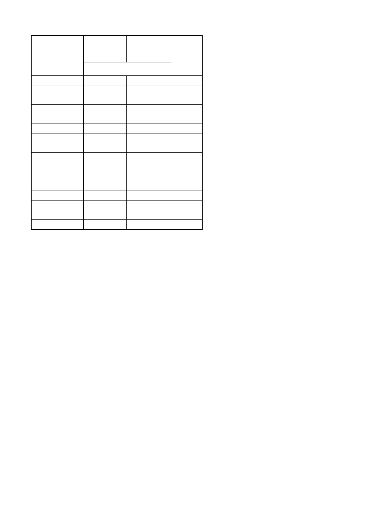
1-2 About The Models
There are many models in the GX-A series and GF-A series with differences in the models being the
minimum display and weighing capacity. In this manual, they are listed collectively by the minimum
display as shown in the table below.
Model Minimum
display
0.001g model 0.001g GX-203A / GX-303A /
GX-403A / GX-603A /
GX-1003A / GX-1603A
0.01g model 0.01g
0.1g model 0.1g GX-6001A / GX-10001A GF-6001A / GF-10001A
□ For the GX-A series, a weight for sensitivity adjustment is built in. It is possible to use functions such
as calibration and auto calibration using the internal mass.
□ For the GF-A series, sensitivity adjustment weights are not built-in. When calibrating, it is necessary
to prepare an external weight.
GX-2002A / GX-3002A /
GX-4002A / GX-6002A /
GX-10002A
Internal mass type General type
Applicable model
GF-203A / GF-303A /
GF-403A / GF-603A /
GF-1003A / GF-1603A
GF-2002A / GF-3002A /
GF-4002A / GF-6002A /
GF-10002A
1-3 Compliance
Compliance with FCC Rules
Please note that this equipment generates, uses and can radiate radio frequency energy. This
equipment has been tested and has been found to comply with the limits of a Class A computing
device pursuant to Subpart J of Part 15 of FCC rules. These rules are designed to provide
reasonable protection against interference when equipment is operated in a commercial environment.
If this unit is operated in a residential area, it may cause some interference and under these
circumstances the user would be required to take, at his own expense, whatever measures are
necessary to eliminate the interference.
(FCC = Federal Communications Commission in the U.S.A.)
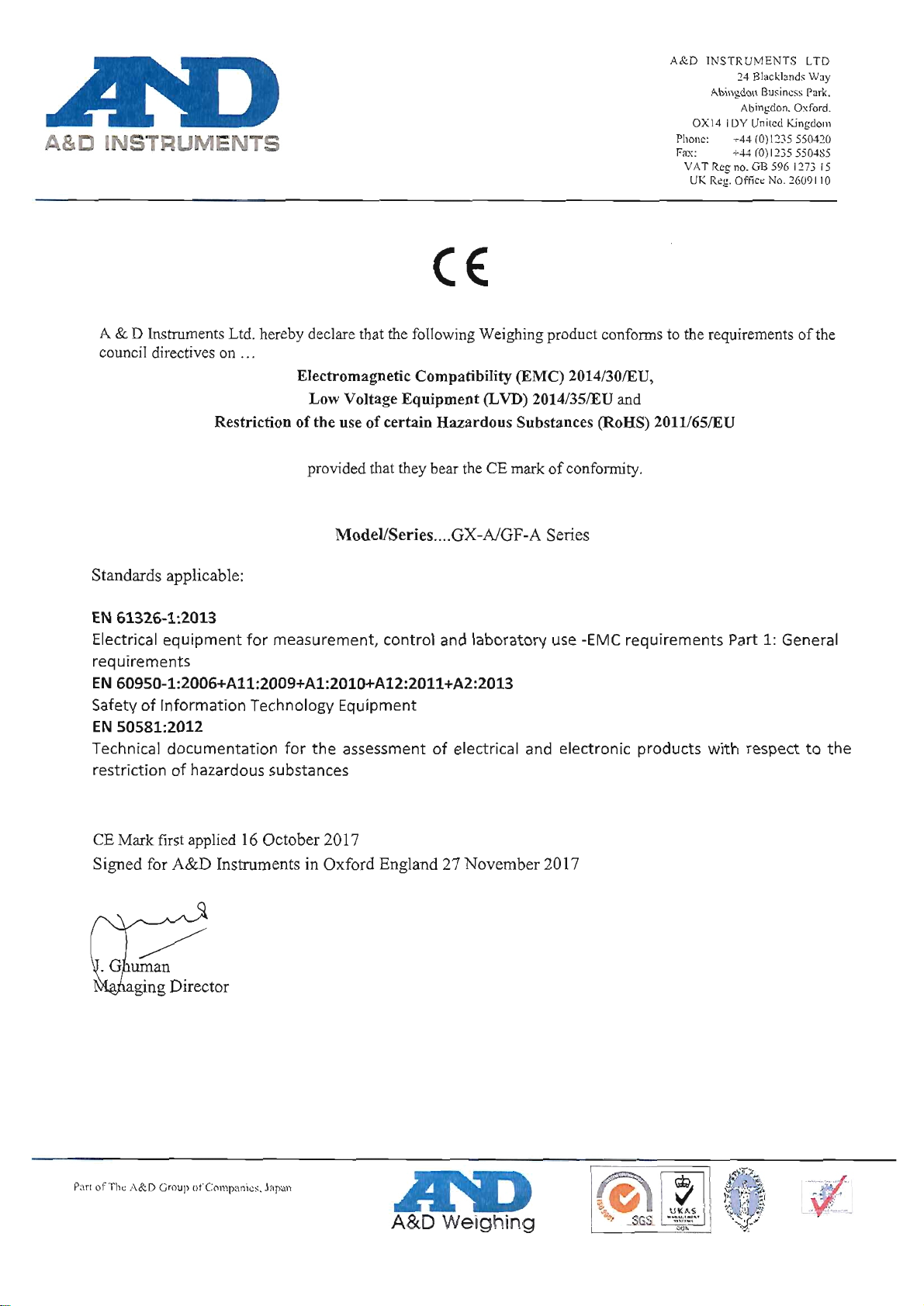
Compliance With Directives of CE mark
This device features radio interference suppression, safety regulation and restriction of Hazardous
Substances in compliance with the following Council Directives
Council directive 2014/30/EU EN61326 EMC directive
Council directive 2014/35/EU EN60950 Safety of Information Technology Equipment
Council directive 2011/65/EU EN50581 Restriction of the use of certain Hazardous Substances
The CE mark is an official mandatory European marking.
Please note that any electronic product must comply with local laws and regulations when sold or
used anywhere outside Europe.
5
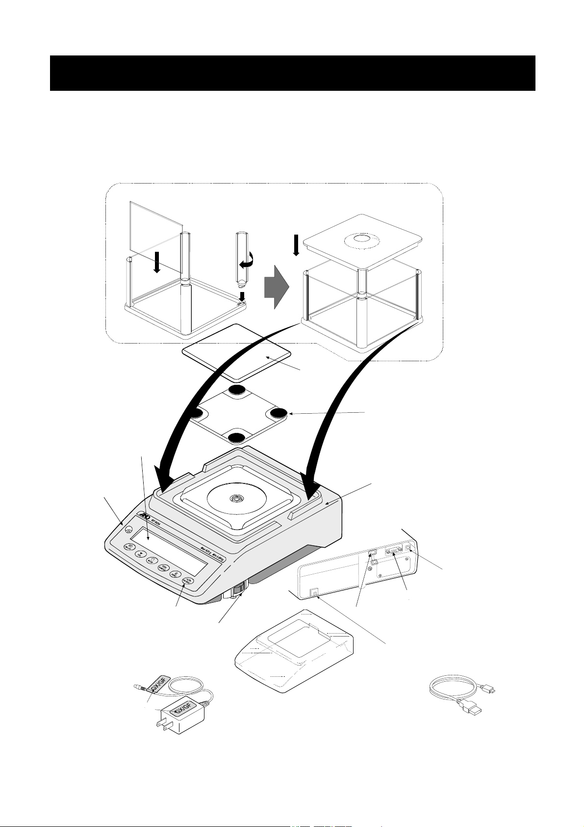
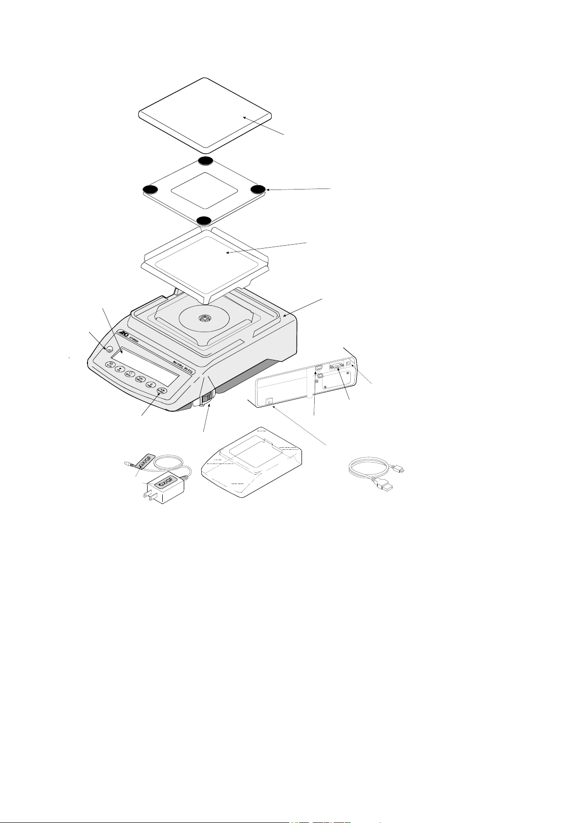
2. Unpacking The Balance
The balance is a precision instrument. Unpack the balance carefully. Keep the packing material to be
used for transporting the balance in the future.
The packing contents depend on the balance model. See the illustrations to confirm that everything is
contained. When shipping options are included, optional accessories may be bundled.
GX-A / GF-A 0.001g models
Assemble the breeze break as shown below.
Follow the numbered sequence.
④
③
②
①
Bubble spirit level
Display
Keys
Leveling foot
Weighing pan
Pan support receptor
Main unit
Main unit rear side
RS-232Cinterface
USB interface
Antitheft hole
(
Please prepare the security cable by yourself.
AC adapter jack
AC adapter plug
)
AC adapter
AC adapter ID
label
Note : Please confirm that the AC adapter
type is correct for your local voltage
and receptacle type.
Main unit cover
USB cable
AX-KO5465-180
7
GX-A / GF-A 0.01g/0.1g models
Display
Bubble spirit level
Keys
AC adapter
Leveling foot
Weighing pan
Main unit rear side
USB interface
Pan support receptor
Dust plate for 10mg
Main unit
AC adapter jack
AC adapter plug
RS-232Cinterface
Antitheft hole
* Please prepare the security cable by
yourself**
AC adapter ID
label
Note : Please confirm that the AC adapter
type is correct for your local voltage
and receptacle type.
Main unit cover
USB cable
AX-KO5465-180
8

2-1 Installing The Balance
Install the balance as follows:
1. Refer to “2-2. PRECAUTIONS” for installing the balance.
2. Assemble the balance as shown in the illustration above.
3. Adjust the leveling feet to level the balance. Confirm it using the bubble spirit level.
4. Confirm that the adapter type is correct for the local voltage and power receptacle type.
5. Connect the AC adapter to the balance. Warm up the balance for at least 30 minutes with nothing
on the weighing pan.
2-2 Precautions
To get the optimum performance from the balance and acquire accurate weighing data, note
the following:
□ Install the balance in an environment where the temperature and humidity are not excessive.
The best operating temperature is about 20℃±2℃ at about 45~60%RH relative humidity.
□ Install the balance where it is free of dust.
□ The weighing table should be solid and free from vibration, drafts and as level as possible.
□ Install the balance in a stable place avoiding vibration and shock. Corners of rooms on the
first floor are best, as they are less prone to vibration.
□ Install the balance where it is not affected by heaters or air conditioners.
□ Install the balance where it is not exposed to direct sunlight.
□ Install the balance away from equipment which produces magnetic fields.
□ Level the balance by adjusting the leveling feet and confirm it using the
bubble spirit level.
□ Warm up the balance for at least 30 minutes. Plug in the AC adapter as
usual.
□ Calibrate the balance before use or after having moved it to another
location. Refer to "8.Calibration".
OK NG
Leveling foot
Caution
Do not install the balance where flammable or corrosive gas is present.
9
Bubble spirit level

How to adjust the bubble spirit level
Wh
bbl
Wh
bbl
Wh
bbl
Wh
bbl
Red circle
Bubble
en the bu
Turn the leveling foot on the front right
in the clockwise direction.
OK NG
es is off to the left.
en the bu
position.
Turn both leveling feet on the front in the clockwise
direction at the same time.
es is off to the backward
Bubble
spirit level
Leveling
Down
Up
foot
en the bu
Turn the leveling foot on the front right
in the clockwise direction.
es is off to the right.
en the bu
es is off to the forward
position.
Turn both leveling feet on the front in the clockwise
direction at the same time.
Down
Leveling foot
Up
2-3 During Use
To acquire accurate weighing data, note the following:
□ Discharge static electricity from the material to be weighed. When a
sample could have a static charge, the weighing data is influenced. If
the ambient humidity becomes 45% or less, insulators such as
plastics are liable to become static electricity. Ground the balance
and try the following.
Eliminate the static electricity by GXA-25, AD-1683 as an accessory.
Or try to keep highly the ambient humidity
Or use a metal shield case.
Or wipe a charged plastic sample with the wet cloth.
□ The breeze break (1mg models only) and the clear main unit
cover are provided as accessories. The breeze break
components may be charged with static electricity when they
are unpacked or when the humidity is low. If the weighing value
is unstable or the balance has a problem with repeatability,
remove the breeze break. Or wipe the clear plates with a
moistened cloth, use an accessory DC static eliminator, GXA-25,
AD-1683 or apply an anti-static spray.
□ This balance uses a strong magnet as part of the balance
assembly, so please use caution when weighing magnetic
materials such as iron. If there is a problem, use the
underhook on the bottom of the balance to suspend the
material away from the influence of the magnet.
The Charged
sample
Metal case
Ground
Magnetic
material
10
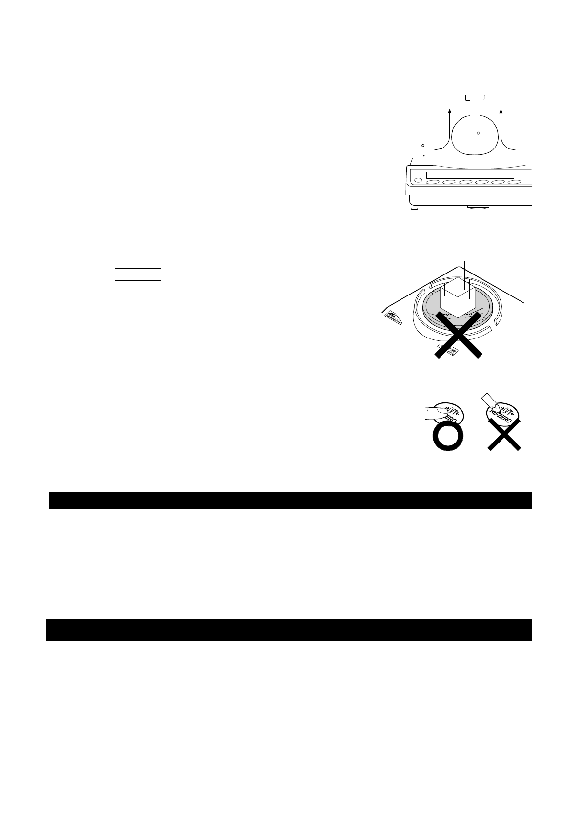
□ Cancel the temperature difference between a sample and the
environment. When a sample is warmer (cooler) than the ambient
temperature, the sample will be lighter (heavier) than the true
weight. This error is due to a rising (falling) draft around the sample.
□ Make each weighing gently and quickly to avoid errors due to
changes in the environmental conditions.
□ When placing a sample on a weighing pan, do not give a strong
shock or do not exceed the weighing capacity. And place in the
center.
□ Do not drop things upon the weighing pan, or place a sample on the
pan that is beyond the balance weighing capacity. Place a sample in
the center of the weighing pan.
□ Do not use a sharp instrument such as a pencil to press the keys.
Use your finger only.
□ Press the RE-ZERO key before each weighing to prevent possible
errors.
□ Take into consideration the affect of air buoyancy on a sample when
more accuracy is required.
□ Keep the balance interior free of dust and foreign materials.
Convection
40 C
20 C
2-4 After Use
□ Avoid mechanical shock to the balance.
□ Do not disassemble the balance. Contact the local A&D dealer if the balance needs service or repair.
□ Do not use organic solvents to clean the balance. Clean the balance with a lint free cloth that is
moistened with warm water and a mild detergent.
□ Avoid dust and water so that the balance weighs correctly. Protect the internal parts from liquid spills
and excessive dust.
2-5 Power Supply
□ When the AC adapter is connected, the balance is in the standby mode if the standby indicator is on.
This is a normal state and does not harm the balance. For accurate weighing, keep the AC adapter
connected to the balance and AC power unless the balance is not to be used for a long period of
time.
11

3.Display Symbols And Key Operation
Display symbols
Battery mark
Preset tare mark
Gross mark
Net mark
Processing indicator
Stabilization indicator
USB connecting mark
Number of statistical data
(Statistical calculation mode)
Displays the weight data relative to the
weighing capacity, in percentage, in the
weighing mode (Capacity indicator)
Standby indicator
Blinking display contents
Data number being displayed
Processing indicator
Auto calibration notice
NET G PT
Response indicators
Comparator indicators
Animal weighing mark
Shock indicators
Unit display
gross zero mark
Interval output mode
standby indicator
Weight data
Blinking
Interal output mode
active indicator
12
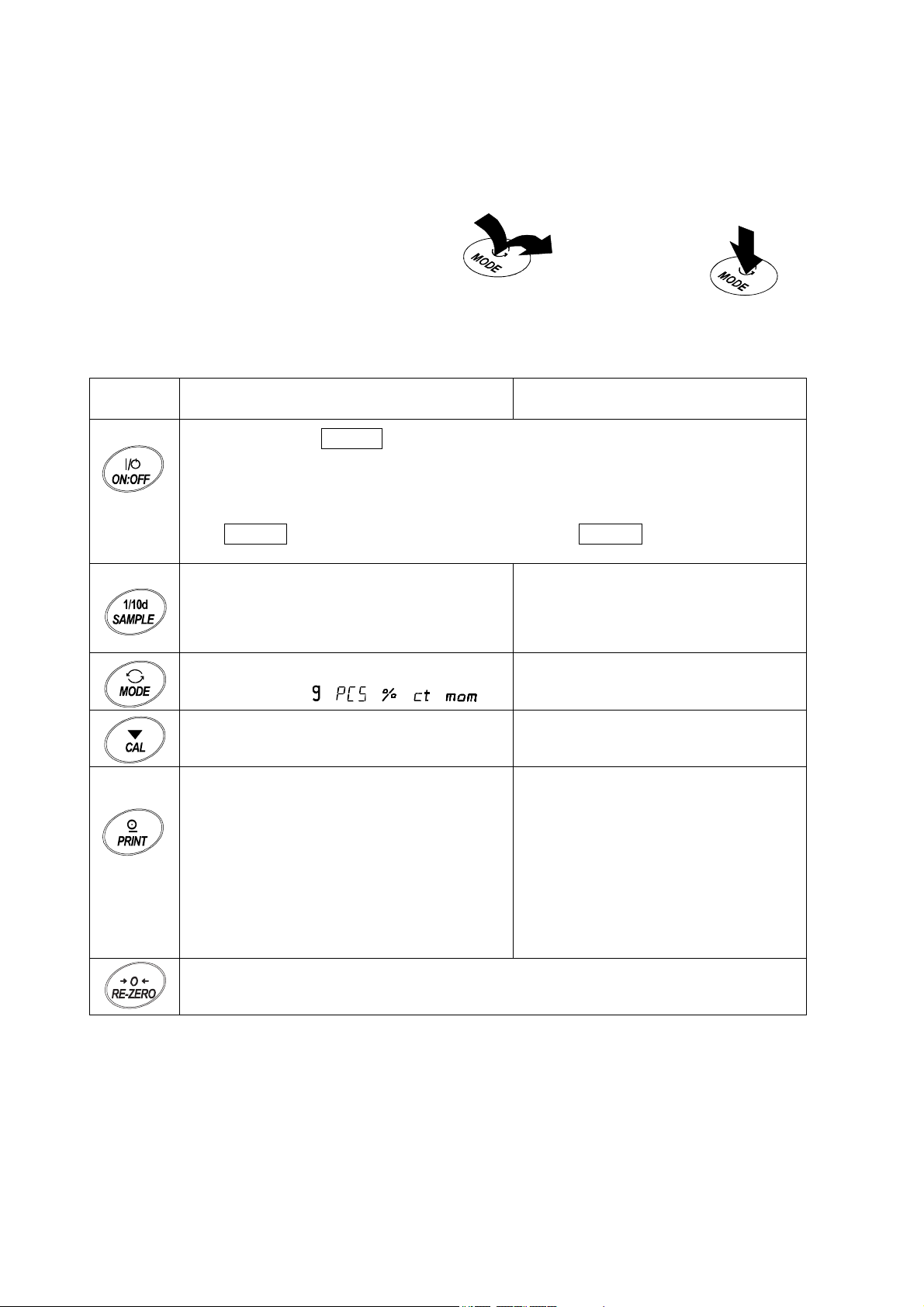
Key operation
Key operation affects how the balance functions. The basic key operations are:
“Press and release the key immediately” or “Press the key”
= normal key operation during measurement
“Press and hold the key”
(Press and release the key immediately.)
Press the key.
Key When pressed When pressed and held
Press and hold the key.
Stores the weighing data in memory or
Turns the display ON:OFF. The standby indicator is displayed when the display is
turned off. The weighing mode is enabled when the display is turned on.
When password function is enable, password input display will be displayed. Refer to
"20-3 Inputting Password Lock When Turning On The Balance"
This ON:OFF key is available anytime. Pressing the ON:OFF key during operation
will interrupt operation and turn the display OFF.
In the weighing mode, turns the minimum
weighing value on and off.
In the counting or percent mode, enters the
sample storing mode.
Switches the weighing units stored in the
function table.
Performs calibration of the balance using
the internal mass.
outputs to a printer or personal computer
depending on the function table settings.
(Factory setting = output)
、 、 、 、 )
(
Enters the function table mode.
Displays other items of the calibration
menu.
Displays other items of the calibration
menu.
Enters mode to change the unit mass
registration number in counting mode.
By changing the function table:
・ Outputs "Title block" and "End
block" for GLP,GMP report.
Sets the display to zero.
・ Displays the data memory menu.
・ Enters mode for reading density
number in flow measurement.
13
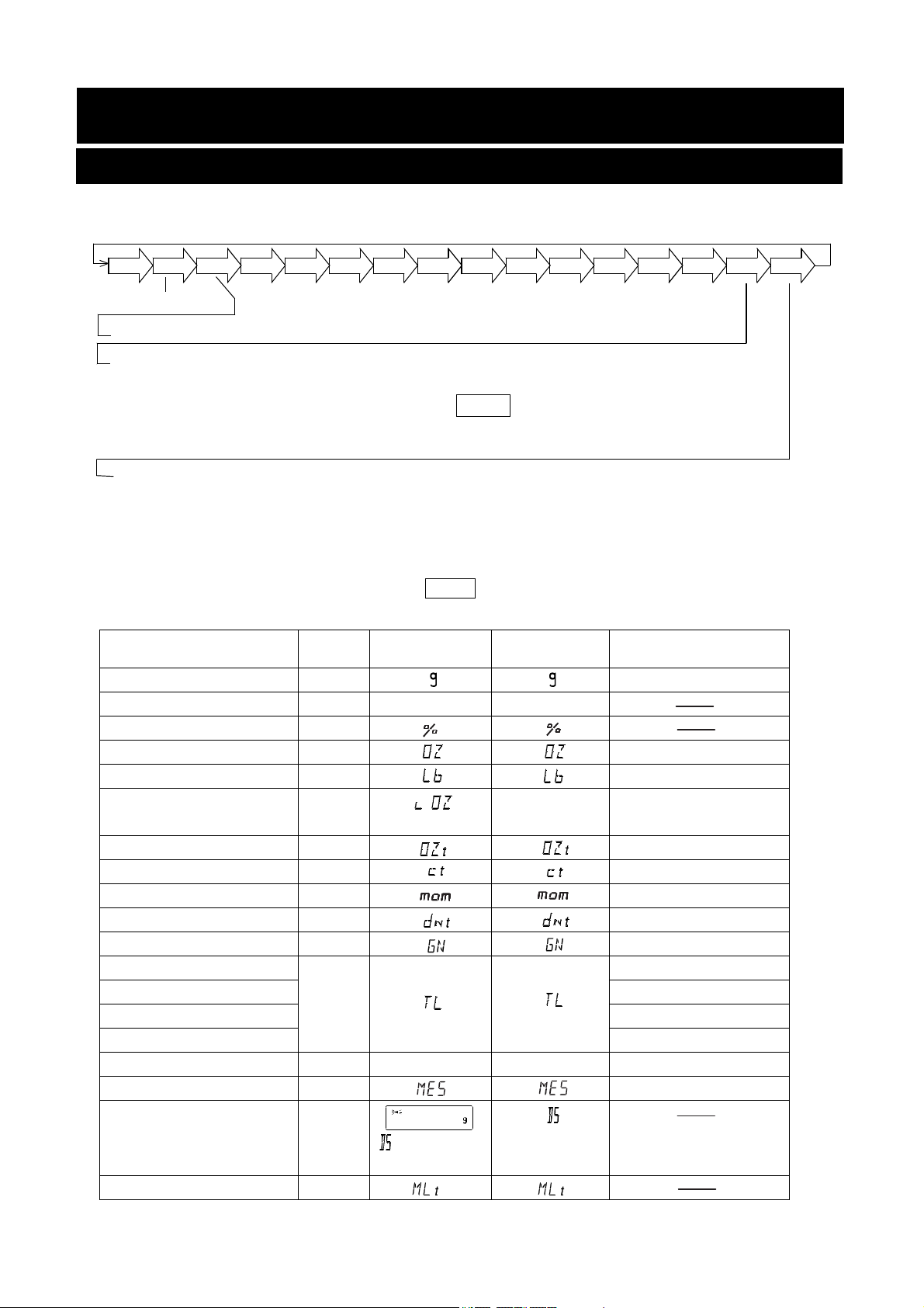
4. Weighing Units
4-1 Units
With the GX-A /GF-A series balance, the following weighing units and weighing modes are available :
g
PC
Pct OZ
Lb
L
OZ
OZt
Counting mode
Percent mode
Density mode (To use this mode, it must be stored in the function table as described on
To select this mode, press the MODE key until the processing indictor
Programmable-unit (No unit displayed. For details, refer to "18. PROGRAMMABLE-UNIT".)
page 15. For details about this mode, refer to "19. DENSITY MEASUREMENT".
blinks with the unit "g" displayed. "DS" appears only when the density
value is displayed.)
A unit or mode can be selected and stored in the function table as described on page 15.
If a weighing mode (or unit of weight) has been turned off, that mode or unit will be missing in the
sequence. Tael has four varieties, one of which can be selected and installed at the factory.
mom
ct
dwt
GN
TL
tol
MES
DS
MLT
To select a unit or mode for weighing, press the MODE key.
For details about the units and modes, see the table below:
Name (unit, mode) Abbrev. Display
Function table
(Storing mode)
Conversion factor
1 g =
Gram g 1 g
Counting mode PCS
p C 5
p C 5
Percent mode %
Ounce (Avoir) OZ 28.349523125 g
Pound Lb 453.59237 g
Pound/Ounce L OZ l0 1Lb=16 oz,
1 oz=28.349523125 g
Troy Ounce OZt 31.1034768 g
Metric Carat ct 0.2 g
Momme mom 3.75 g
Pennyweight dwt 1.55517384 g
Grain (UK) GN 0.06479891 g
Ta el (HK general, Singapore)
Tael (HK jewelry) 37.429 g
TL
37.7994 g
Tael (Taiwan) 37.5 g
Tael (China) 31.25 g
Tola (India) tol 11.6638038 g
to1
to1
Messghal MES 4.6875 g
Density mode
(See note below)
DS
is used to
show the density.
Programmable-unit (Multi-unit) M LT
Note: The blinking processing indicator with “g” indicates that the density mode is selected.
14

The tables below indicate the weighing capacity and the minimum display for each unit, depending on the
balance model.
Unit
Gram
Ounce (Avoir)
Pound
Pound/Ounce 0Lb 7.76oz
Troy Ounce
Metric Carat
Momme
Pennyweight
Grain (UK)
Tael (HK general,
Singapore)
Tael (HK jewelry)
Tael (Taiwan)
Tael (China)
Tola (India)
Messghal
GX-203A GX-303A GX-403A GX-603A GX-1003A GX-1603A
GF-203A GF-303A GF-403A GF-603A GF-1003A GF-1603A
220 320 420 620 1100 1620
7.76 11.28 14.81 21.86 38.80 57.14
0.485 0.705 0.925 1.366 2.425 3.571
7.07 10.28 13.50 19.93 35.36 52.08
1100 1600 2100 3100 5500 8100
58.6 85.3 112.0 165.3 293.3 432.0
141 205 270 398 707 1041
3395 4938 6481 9568 16975 25000
5.82 8.46 11.11 16.40 29.10 42.85
5.87 8.54 11.22 16.56 29.38 43.28
5.86 8.53 11.20 16.53 29.33 43.20
7.04 10.24 13.44 19.84 35.20 51.84
18.8 27.4 36.0 53.1 94.3 138.8
46.9 68.2 89.6 132.2 234.6 345.6
Capacity
0Lb 11.28oz 0Lb 14.81oz 1Lb 5.86oz 2Lb 6.80oz 3Lb 9.14oz
Minimum
0.000005
display
0.001
0.00005
0.01oz
0.00005
0.005
0.0005
0.001
0.02
0.00005
0.00005
0.00005
0.00005
0.0001
0.0005
Unit
Gram 2200 3200 4200 6200 10200 0.01
Ounce (Avoir) 77.6 112.8 148.1 218.6 359.7 0.0005
Pound 4.85 7.05 9.25 13.66 22.48 0.00005
Pound/Ounce 4Lb 13.60oz 7Lb 0.87oz 9Lb 4.15oz 13Lb 10.69oz 22Lb 7.79oz 0.01oz
Troy Ounce 70.7 102.8 135.0 199.3 327.9 0.0005
Metric Carat 11000 16000 21000 31000 51000 0.05
Momme 586 853 1120 1653 2720 0.005
Pennyweight 1414 2057 2700 3986 6558 0.01
Grain (UK) 33951 49383 64815 95680 157410 0.2
Tael (HK
general,
Singapore)
Tael (HK jewelry) 58.7 85.4 112.2 165.6 272.5 0.0005
Tael (Taiwan) 58.6 85.3 112.0 165.3 272.0 0.0005
Tael (China) 70.4 102.4 134.4 198.4 326.4 0.0005
Tola (India) 188 274 360 531 874 0.001
Messghal 769 682 896 1322 2176 0.005
GX-2002A GX-3002A GX-4002A GX-6002A GX-10002A
GF-2002A GF-3002A GF-4002A GF-6002A GF-10002A
Capacity
58.2 84.6 111.1 164.0 269.8 0.0005
Minimum
display
15
Unit
Gram 6200 10200 0.1
Ounce (Avoir) 218 359 0.005
Pound 13.6 22.4 0.0005
Pound/Ounce 13Lb 10.69oz 22Lb 7.79oz 0.01oz
Troy Ounce 199 327 0.005
Metric Carat 31000 51000 0.5
Momme 1653 2720 0.05
Pennyweight 3986 6558 0.1
Grain (UK) 95680 157410 2
Tael (HK general,
Singapore)
Tael (HK jewelry) 165.0 272.0 0.005
Tael (Taiwan) 165.0 272.0 0.005
Tael (China) 198.0 326.0 0.005
Tola (India) 531.0 874.0 0.01
Messghal 1322 2176 0.05
GX-6001A GX-8001A Minimum
GF-6001A GF-8001A
Capacity
164.0 269.0 0.005
display
16
4-2 Storing Units
The units or modes can be selected and stored in the function table. The sequence of displaying the units
or modes can be arranged to fit the frequency of use.
The units stored are maintained in non-volatile memory, even if the AC adapter is removed.
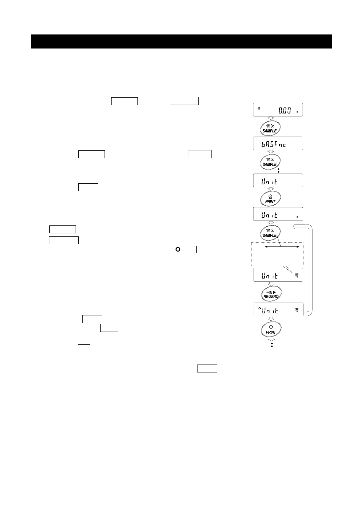
Select a unit or mode and arrange the sequence of display as follows:
1 Press and hold the SAMPLE key until ba5fnc of the
function table is displayed, then release the key.
Press and hold
2 Press the SAMPLE key several times to display 1Unit .
3 Press the PRINT key to enter the unit selection mode.
4 Specify a unit or mode in the order to be displayed using
the following keys.
SAMPLE key To sequentially display the units.
RE-ZERO key To specify a unit or mode. The
stabilization indicator
appears when the displayed unit or
mode is specified.
If the key is pressed in units already
selected, the stability mark disappears.
5 Press the PRINT key to store the units or modes. The
balance displays end and then displays the next menu of
the function table.
Press
several times
Select
Displays the units
sequentially.
Specify
Store
6 Press the CAL key to exit the function table. Then the balance
returns to the weighing mode with the selected unit.
7 To select other unit or mode for weighing, press the MODE key.
17
Unit setting example
The example below sets the units in the order with g (gram) as the first unit followed by pc (counting
mode).
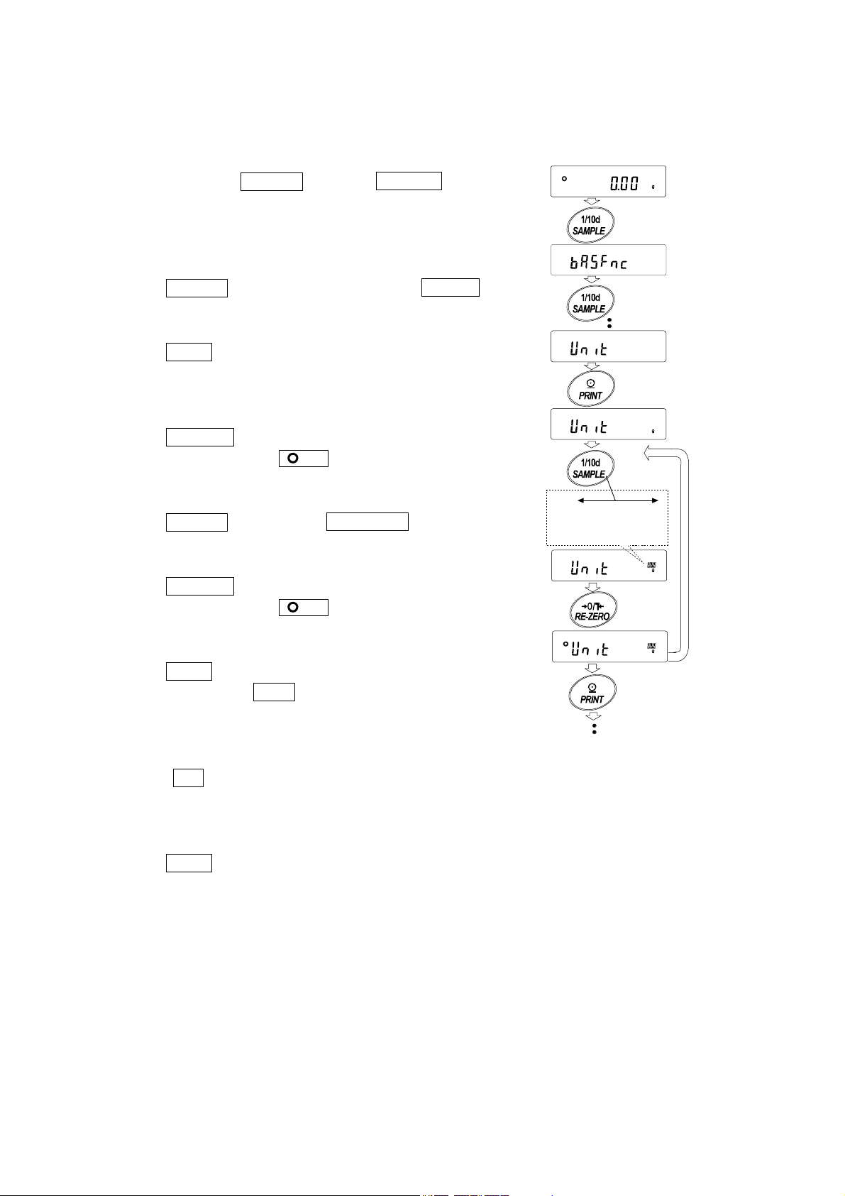
1 Press and hold the SAMPLE key until ba5fnc of the
function table is displayed, then release the key.
2 Press the SAMPLE key several times to display 1Unit .
3 Press the PRINT key to enter the unit selection mode.
4 Press the RE-ZERO key to specify the unit of g
The stabilization indicator appears when the unit
is specified.
5 Press the SAMPLE key to display 1Unit pC5 .
6 Press the RE-ZERO key to specify the unit of pc
The stabilization indicator appears when the unit
is specified.
7 Press the PRINT key to store the units.
The balance displays end and then displays the next
menu item of the function table.
8 Press the CAL key to exit the function table. Then the
balance returns to the weighing mode with g,the unit
selected first.
9 Press the MODE key to switch between g and pc (gpcs).
Displays the units
sequentially.
Press and hold
Press
several times
Select
Specify
Store
18
5.Weighing
5-1 Basic Operation
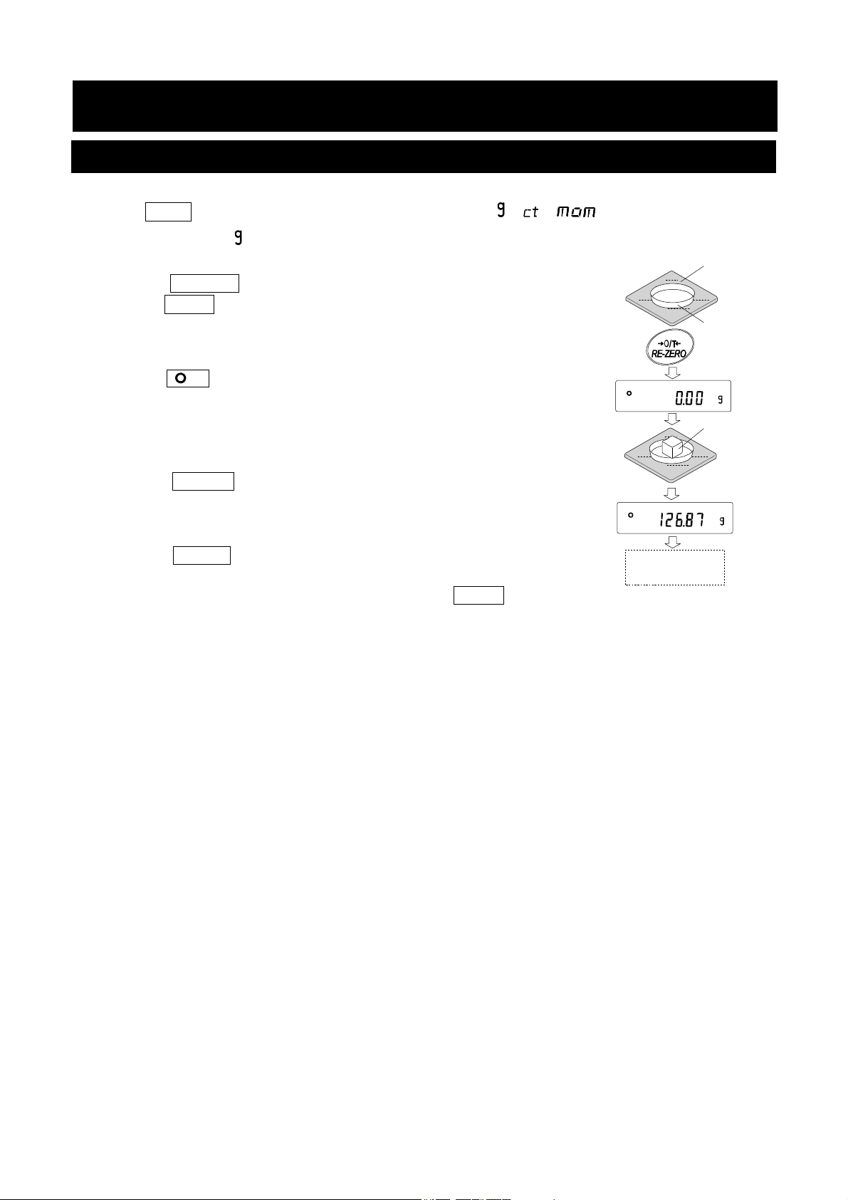
1. Press MODE key, and then select the appropriates units(
In this case, select " ".
2. Place a container on the weighing pan, if necessary.
Press the RE-ZERO key to cancel the weight (tare). The balance
displays 0.00 g. (The decimal point position depends on the
balance model.)
3. Place a sample on the pan or in the container. Wait for the stabilization
indicator
Remove the sample and container from the pan.
Notes
□ Press the SAMPLE key to turn on or off the minimum weighing value.
□ The weighing data can be stored in memory. For details, refer to “12. Data
Memory”.
□
When the ON:OFF key is pressed with a container placed on
the weighing pan and weighing is started, the balance
automatically cancels the weight (tare) and displays 0.00 g.
to be displayed. Read the value.
, , )
Weighing
pan
Container
Sample
Remove the
sample
19
About the operation at when power is turned on
The balance will decide the reference zero point when the power is turned on (AC adapter is connected).
Depending on the load condition at that time, it will automatically judge whether to perform zero or tare
operation. The condition for determining which is used is "power on zero range", and when power on zero
range is exceeded, the tare subtraction operation is performed.
About re-zero operation
By pressing the RE-ZERO key, the display can be changed to zero.
Re-zero with the RE-ZERO key will automatically determine whether zero or tare operation is
performed.
The condition for determining which is used is "zero range", and when zero range is exceeded, the tare
subtraction operation is performed.
About measurement range
For the balance, the range that can be weighed is determined by model.
The total amount (net amount + tare quantity) up to the maximum display of each model is displayed, and
when the maximum display is exceeded, E is displayed to indicate that the weighing range is
exceeded.
When in excess in negative, -E is displayed.
Model Power on zero range Zero range -E display range
GX-203A GF-203A
GX-303A GF-303A
GX-403A GF-403A
GX-603A GF-603A
GX-1003A GF-1003A
GX-1603A GF-1603A
GX-2002A GF-2002A
GX-3002A GF-3002A
GX-4002A GF-4002A
GX-6002A GF-6002A
GX-10002A GF-10002A
GX-6001A GF-6001A
GX-10001A GF-10001A
Approx.±100g Approx.±4g
Approx.±100g Approx.±6g
Approx.±100g Approx.±8g
Approx.±100g Approx.±12g
Approx.±100g Approx.±20g
Approx.±100g Approx.±32g
Approx.±1kg Approx.±40g
Approx.±1kg Approx.±60g
Approx.±1kg Approx.±80g
Approx.±1kg Approx.±120g
Approx.±1kg Approx.±200g
Approx.±1kg Approx.±120g
Approx.±1kg Approx.±200g
Approx.-100g or less
Approx.-100g or less
Approx.-100g or less
Approx.-100g or less
Approx.-100g or less
Approx.-100g or less
Approx.-1kg or less
Approx.-1kg or less
Approx.-1kg or less
Approx.-1kg or less
Approx.-1kg or less
Approx.-1kg or less
Approx.-1kg or less
20
5-2 Counting Mode(PCS)
This is the mode to determine the number of objects in a sample based on the standard sample unit
mass. Unit mass means the mass of one sample. The smaller the variables in each sample unit mass is,
the more accurate the counting will be. This series balance is equipped with the Automatic Counting
Accuracy Improvement (ACAI) function to improve the counting accuracy.
Note
※ For counting, use samples that have a unit mass at least ten times greater than that of the minimum
display in grams.
※ If the sample unit mass variable is too large, it may cause a counting error.
※ To improve the counting performance, use the ACAI function frequently or divide the samples into
several groups and count each group.
Selecting the counting mode
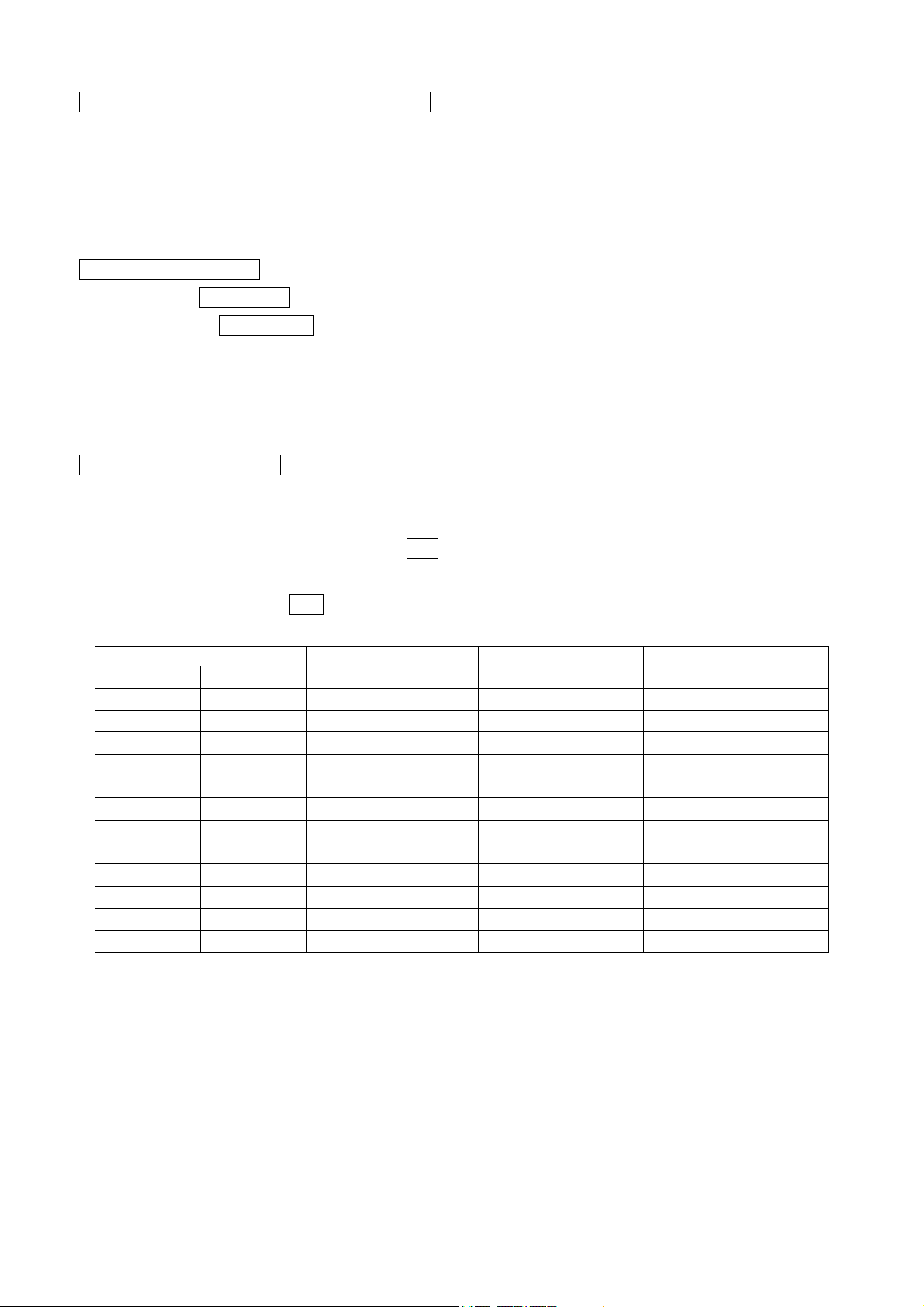
1. Press the MODE key to select pC5 ( pC5 = unit)
Storing a sample unit mass
2. Press the SAMPLE key to enter the sample unit mass storing
mode. Even in the storing mode, pressing the MODE key will
switch to the next mode.
3. To select the number of samples, press the SAMPLE key
several times. It may be set to 5, 10, 25, 50 or 100.
Note
A greater number of samples will yield more accurate counting result.
4. Place a container on the weighing pan, if necessary. Press the
RE-ZERO key to cancel the weight (tare). The number specified
in step 3 appears.
25 0 is displayed if 25 is selected in step 3.
5. Place the number of samples specified on the pan. In this example, 25
pieces.
6. When PRINT key pressed, unit mass is stored and changes the count
display. (eg: when the number is 25,
Note
※ If the balance judges that the mass of the samples is TOO light
to acquire accurate weighing, it displays an error requiring the
addition of more samples to the specified number and press the
PRINT key. When the unit mass is stored correctly, the balance
proceeds to the counting mode.
※ If the balance judges that the mass of the samples is too light and is
not adequate to be used as the unit mass, it displays lo .
25 pC5 is displayed.
Weighing pan
Container
Sample
(25 pieces)
place
※ Registered unit mass is remembered even when the power is turned off.
Number mode(counting)
7. Counting is possible.
21
(The couting result)
Counting Mode Using The ACAI Function
The ACAI is a function that improves the accuracy of the unit mass automatically by increasing the number of
samples as the counting process.
ACAI: Automatic Counting Accuracy Improvement
After registering unit mass of "Step 6", proceed to the following "Step 8".
8. If a few more samples are added, the processing indicator turns on. To
prevent an error, add three or more. The processing indicator does not turn
on if overloaded. Try to add the same number of samples as displayed.
9. The balance re-calculates the unit mass while the processing indicator is blinking. Do not touch the
balance or samples on the pan until the processing indicator turns off.
10. Counting accuracy is improved when the processing indicator turns off.
11. Each time the above operation is performed, a more accurate unit mass will be obtained. There is
no definite upper limit of ACAI range for the number of samples exceeding 100. Try to add the
same number of samples as displayed.
12. Remove all the samples used in ACAI and proceed with the counting operation using the improved
unit mass.
Note ACAI will not function on the unit mass entered using the keys, or
digital input mode.
Processing mark
Storing the unit mass
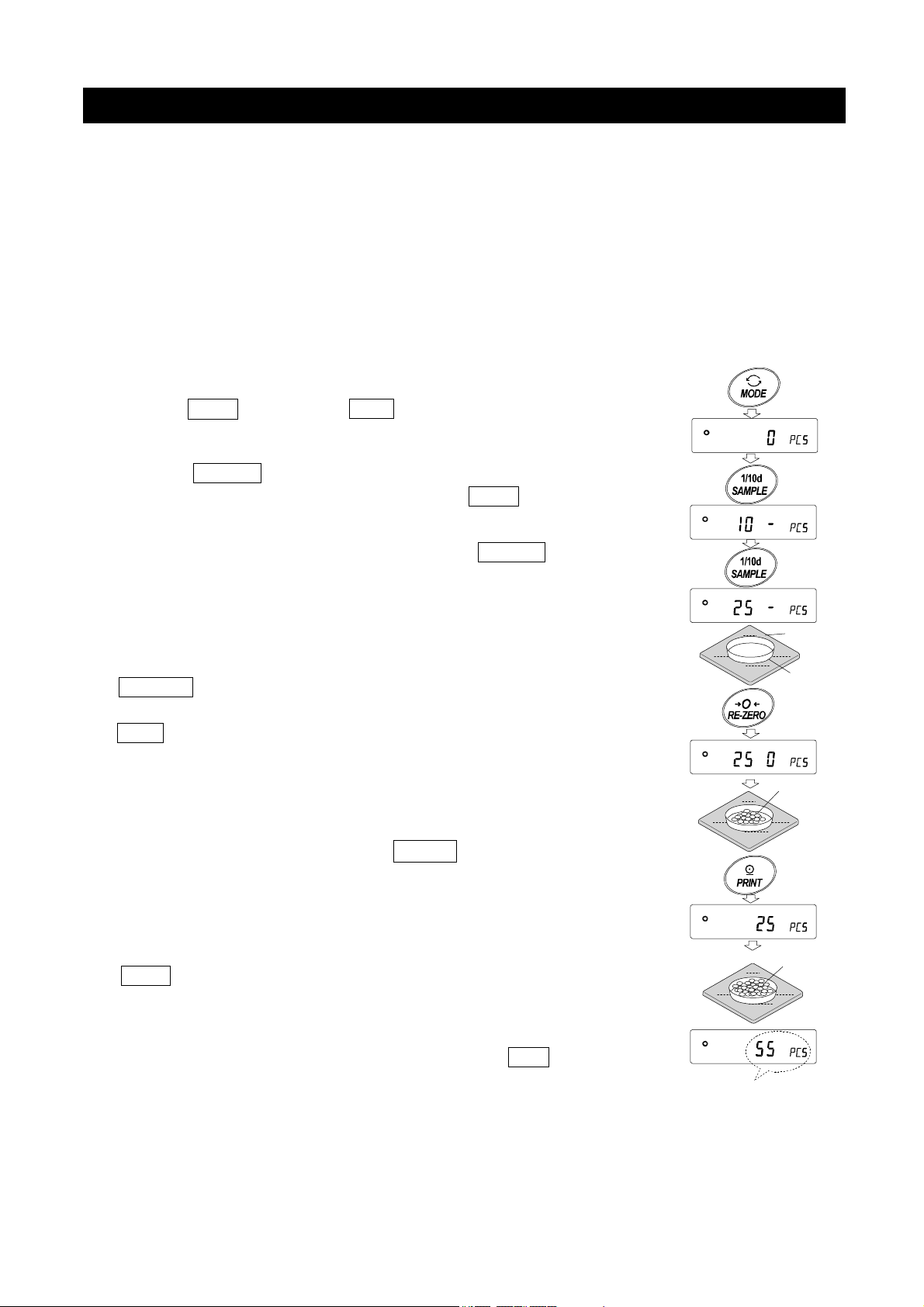
By using the data memory function, 50 instances of storing a sample
unit mass can be stored.
1. Set the function setting item "Data memory function ( ) " to
"Stores unit mass in counting ( ) " .Refer to "10.Function
Ta bl e ".
2. The displayed "P**" is the selected unit mass registration number.
3. Press and hold the PRINT key to switch to the mode to change the
unit mass registration number.
RE-ZEROkey Changes the registration number(+)
MODEkey Changes the registration number (-)
PRINTkey Decides on the displayed registration number.
CALkey Cancel the displayed registration number.
4. Multiple unit masses can be stored by registering them with different unit mass registration numbers.
Note
※ Unit weight can be read by ″UN:mm″command.
(mm corresponds to P01 to P50 with 01 to 50.)
※ The read unit mass can output by ″?UW ″command and can be changed by ″?UW ″
command.
Press and Hold
Note
※ ACAI cannot be used for the read unit mass.
22
5-3 Percent Mode (%)
The percent mode displays the weighting value in percentage compared to a 100% reference
mass and is used for target weighing or checking the sample variance.
Selecting The Percent Mode
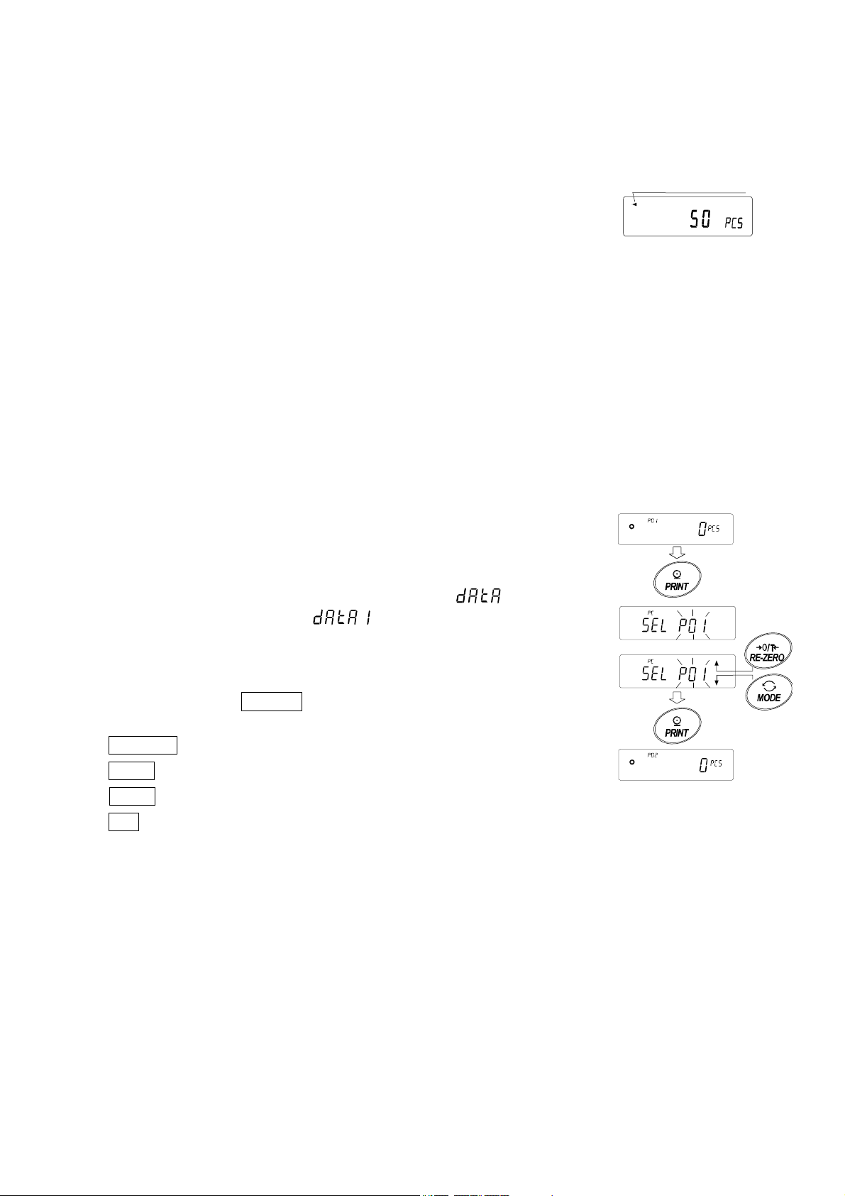
1. Press the MODE key to select the unit % (Percent mode).
Storing The 100% Reference Mass
2. Press the SAMPLE key to enter the 100% reference mass
storing mode.
Even in the storing mode, pressing the MODE key will
switch to the next mode.
3. Place a container on the weighing pan, if necessary. Press the
key to cancel the weight (tare). The balance displays 100 0 %.
4. Place the sample to be set as the 100% reference mass on the pan or in the
container.
5. Press the PRINT key to store the reference mass. The
balance displays 100.00 %. (The decimal point position
depends on the reference value. The reference mass stored,
even if the AC adapter is removed, is maintained in
non-volatile memory.)
Note
RE-ZERO
Weighing pan
Container
Sample
(100%)
□ If the balance judges that the mass of the sample is too light to be used
as a reference, it displays
□ The displayed percentage is based on the 100% reference mass.
100% mass Decimal point position
Minimum display
0.001gmodel
Minimum display 0.01g
model
Minimum display 0.1g
model
□ Registered values are stored even when the power is turned off.
6. Remove the sample
lo .
0.100g ~ 0.999g 1%
1.000g ~ 9.999g 0.1%
10.000g ~ 0.01%
1.00g ~ 9.99g 1%
10.00g ~ 99.99g 0.1%
100.00g ~ 0.01%
1.0g ~ 9.9g 1%
10.0g ~ 99.9g 0.1%
100.0g ~ 0.01%
place
Display % of weighing object
Reading the percentage
7. Please a sample to be compared to the reference mass on the pan.
The displayed percentage is based on the 100% reference mass.
23

5-4 Animal Weighing Mode(Hold Function)
This is the mode to weigh a moving object such as an animal, even when the display of the
weighing data fluctuates. The hold function allows the average weight of the animal to be
displayed. To use the hold function, set the function in the function table. Refer to "10. Function
Table" and "10-3. Description Of The Class "Environment, Display" " for details.
24
6. Impact Detection Function
The GX-A / GF-A series has a function to detect impact to the mass sensor section and to display the
impact level.
By lowering the impact level at the time of loading, it is possible not only to alleviate variation in the
weighing value but also to reduce the risk of failure of the mass sensor section.
Especially when incorporating the balance in a production line, etc. and weighing by means such as an
automated system, impact to the sensor may be applied greater than expected.
When designing automatic systems and the like, it is recommended that you minimize the impact level
as much as possible while checking the shock indicator.
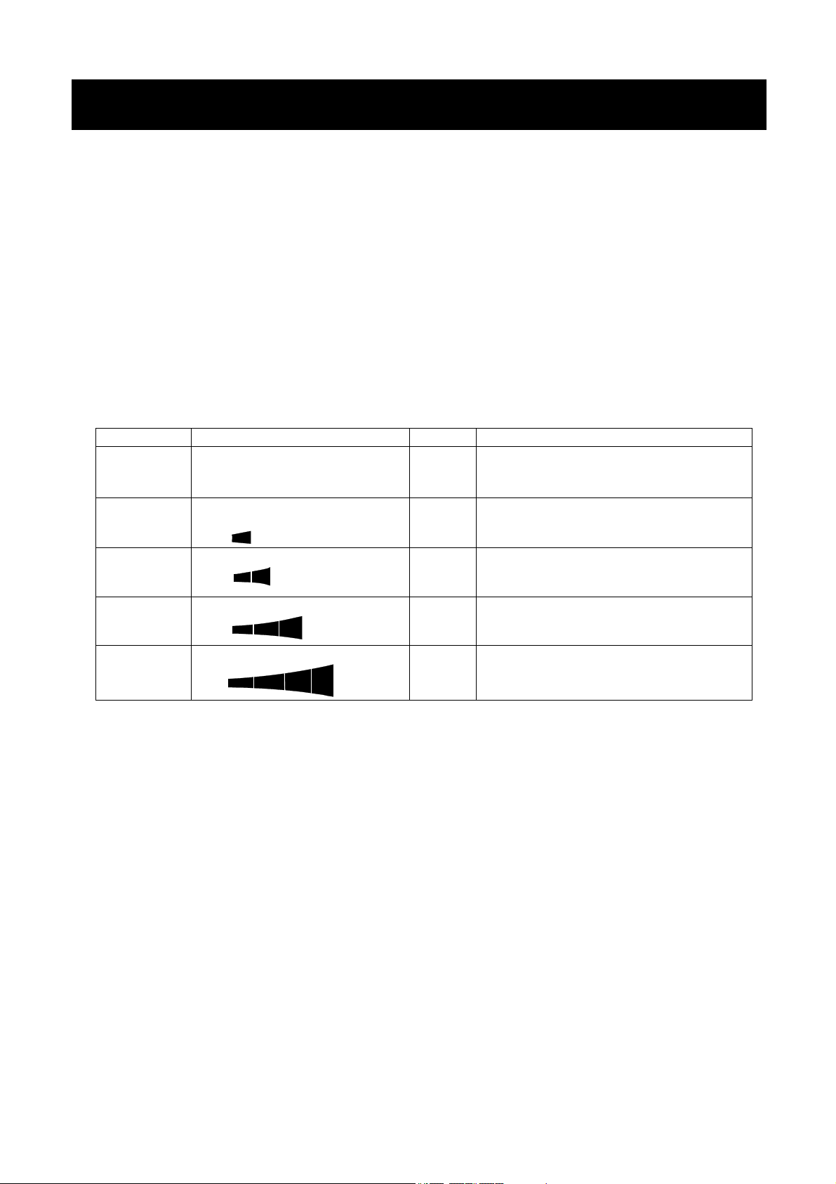
Impact level display is from level 0 to level 4, 5level.
Impact level Shock indicator Buzzer Contents
0
No
No
Safe
1
2
3
4
SHOCK
SHOCK
SHOCK
SHOCK
No
No
One
beep
Two
beep
Caution
Caution:Consider impact mitigation
Warning:Do not apply greater impact
Danger:Sensor may be damaged
Note
□ Impact on the weighing sensor may be applied to the weighing pan at time of loading, or it may be
applied from the table on which the balance is installed.
The impact detection function also works for impact applied from the table.
25
7. Response Adjustment / Self Check Function
This function stabilizes the weight value, reducing the influence on weighing that is caused by drafts and/or
vibration at the place where the balance is installed. This function adjusts by automatically analyzing the
environment or by hand-operation. The function has three stages as follows : Changing the weighing speed
changes the display refresh rate.
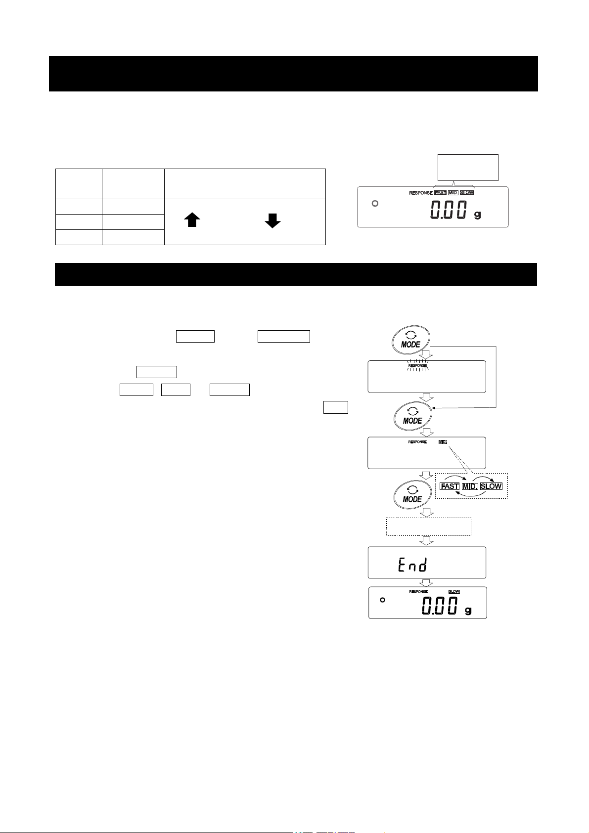
Display
FAST
MID.
SLOW
Function
setting
Cond 0
Cond 1
Cond 2
Response characteristic
Fast response, Sensitive value
Slow response, Stable value
7-1 Response Adjustment
Response adjustment can be changed by the following method.
Response
indicator
1. Press and hold the
then release the key.
2. Press the
Either FAST , MID or SLOW can be selected.
3. After a few seconds of inactivity the balance displays end . Then, it
returns to the weighing mode and displays the updated response
indicator.
The response indicator remains displayed for a while.
Note
The value set for response adjustment can be changed by
"Condition Cond " of "Environment display" in the Function
Ta bl e .
For the setting method, refer to "10.Function Table".
MODE key to select a weighing speed.
MODE key until RESPONSE is displayed, and
Press and Hold
Release and
press again
Each pressing switches
the indicators
After a while
26
7-2 Self-Check-Function / Automatic Setting Of Minimum
Weight Value
With the self-diagnosis function confirmation and display of repeatability can be performed in addition to
failure diagnosis, and whether or not the balance's performance is being exhibited can be easily
checked.
It is also possible to display and register the reference value of the minimum weighing value using
repeatability data.
For details of the minimum weighing value, refer to the technical information on our website.
(http://www.aandd.co.jp/adhome/products/balance/tecdoc_balance.html)
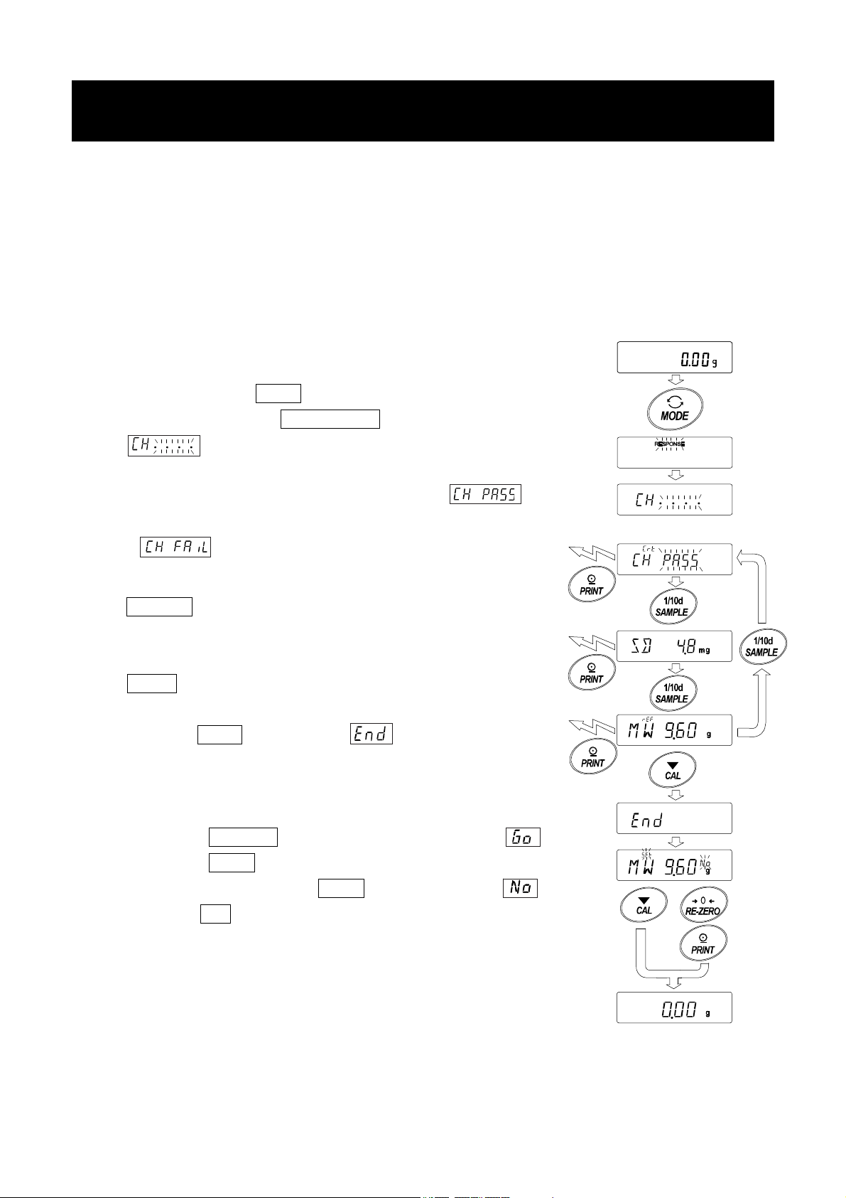
1. Press and hold the MODE key while weighing is displayed.
2. Release the key when RESPONSE display blinks.
3. displays and the self-diagnosis function is started.
4. When the diagnosis is completed, the diagnosis result is displayed.
When there are no problems in the balance, the
display blinks .
If is displayed blinking, there is a possibility that a fatal
fault has occurred in the balance. Please request repair.
SAMPLE key It is possible to switch the display of
diagnostic result, repeatability, minimum
weight value.
PRINT key The displayed contents are output.
5. Press the CAL key to display and move to the display
for minimum weighing value registration.
6. When registering as minimum weighing value of minimum weight value
display warning function performs the following.
Press the RE-ZERO key to change No/Go and display .
Press the PRINT key.
If not registered, press the PRINT key while displaying ,
or press CAL. Return to the weighing display.
Output
Output
Output
No change
No/Go
Switch
setting
* For minimum weighing warning function, refer to " 16.Minimum
Weighting Warning Function".
Note
For the minimum weighing warning function, settings can only be made
when logged in as administrator (AdMin) if the password lock function is
turned on.
27

8.Calibration
Since the balance's resolution is high, weighing values may change due to gravity and daily
environmental changes. It is necessary to perform calibration (sensitivity adjustment) with the weight in
order to keep the weighing values from changing even if gravity or the environment changes.
It is recommended that you calibrate if the balance is installed for the first time or relocated, or when
the weighing values change significantly in daily inspection, etc.
Adjustment means to adjust the weighing value of the balance using the reference weight or internal
mass. Calibration is to weigh with the reference weight and compare how much the result deviates
from the reference value. (Adjustment is not performed in calibration.)
Calibration (Sensitivity adjustment)
Auto calibration ------------------------------------------ Automatically adjust the balance using the internal mass
depending on the temperature change of the operating
environment or the set time and interval time.(GX-A
series)
Calibration test using the internal mass ---------- Using the internal mass, adjust the balance with a single
touch.
Calibration test using an external weight --------- Using an external mass, adjust the balance with an
external mass.
Calibration test(Sensitivity calibration)
Calibration test with your own weight -------------- Output the result of checking the accuracy of weighing
using your own weight.
*No adjustment is made.
Caution
□ Do not allow vibration or drafts to affect the balance during calibration.
□ To output the data for GLP/GMP using the RS-232C interface, set "GLP/GMP output (info)" of "Data
output (dout)". Refer to "10. Function Table". The time and date can be added to the GLP/GMP report.
If the time or date is not correct, adjust them. Refer to "10-4 Clock and Calendar Function".
□ The calibration and calibration test data can be stored in memory. To store them, set "Data memory
(data)" .
□ The accuracy of the weight used in calibration affects the accuracy of the balance after calibration.
□ Select the mass to be used for calibration and calibration tests from the table below.
28

Model Usable calibration weight
GX-203A , GF-203A 50g, 100g, 200g 200g
GX-303A, GF-303A 50g, 100g ~ 300g (100g interval) 200g
GX-403A, GF-403A 50g, 100g ~ 400g (100g interval) 400g
GX-603A, GF-603A 50g, 100g ~ 600g (100g interval) 500g
GX-1003A, GF-1003A 50g, 100g ~ 1000g (100g interval) 1000g
GX-1603A, GF-1603A 50g, 100g ~ 1600g (100g interval) 1000g
GX-2002A, GF-2002A 500g, 1000g, 2000g 2000g
GX-3002A, GF-3002A 500g, 1000g ~ 3000g (1000g interval) 2000g
GX-4002A, GF-4002A 500g, 1000g ~ 4000g (1000g interval) 4000g
GX-6002A, GF-6002A 500g, 1000g ~ 6000g (1000g interval) 5000g
GX-10002A, GF-10002A 500g, 1000g ~ 10000g (1000g interval) 10000g
Factory
setting
Adjustable
range
-9.999g ~
+9.999g
-99.99g ~
+99.99g
GX-6001A, GF-6001A 500g, 1000g ~ 6000g (1000g interval) 5000g
GX-10001A, GF-10001A 500g, 1000g ~ 10000g (1000g interval) 10000g
-999.9g ~
+999.9g
Display
This indicator means "In process of measuring calibration data".
Do not allow vibration or drafts to affect the balance while the indicator is
displayed.
8-1 Automatic Self Calibration For The GX-A Series
This function automatically calibrates the balance when the balance detects an ambient temperature
change. If GLP output is selected in the function table, the balance outputs the calibration report or
stores the data in memory.
In the auto calibration mode, either the temperature change, the setting time, or the interval time can be
set with the function setting .
For the setting time, the three function setting of , and can be set.
Interval time can be set from 0.5h to 24h with function setting .
Caution
If something is on the weighing pan, the balance judges that it is in use and does not perform automatic self
calibration.
The criteria that the balance judges is in use are as follows.
0.001g models 0.01g models 0.1g models
Lower than 2g Lower than 20g Lower than 20g
To maintain the calibrated state, keep the weighing pan clear while not in use.
Indicates that the balance detects a change in ambient temperature and
automatic self calibration will start. If the balance is not used for a few minutes
with this indicator ( ) blinking, the balance performs automatic self calibration.
The blinking duration depends on the environment.
Indicates that the balance is measuring calibration data. Do not allow vibration
or drafts to affect the balance while this indicator is displayed. After calibration,
the balance returns to indicate the previous display.
Note The balance can be used while the indicator blinks. But, it is recommended that to maintain
the accuracy, stop using the balance and confirm that there is nothing on the pan and allow
the balance to perform self calibration.
29

8-2 One-Touch Calibration For The GX-A Series
This function calibrates the balance using the internal mass.
Step1 Connect the AC adapter and warm up the balance for at least 30 minutes with nothing on the
weighing pan.
Step 2 Press the CAL key.The balance displays Calin and performs calibration using the internal
mass. Do not allow vibration or drafts to affect the balance.
Step 3 The balance displays end after calibration. If the "GLP output (info)" parameter of the function
table is set to "1" or "2", the balance displays glp and outputs the "calibration report" using the
RS-232C interface or stores the data in memory. Refer to "11-3. GLP Report" and "Data memory
(data)" of the function table for details.
Step 4 The balance will automatically return to the weighing mode after calibration.
About the internal mass
The value of the internal mass may change due to aging, corrosion or other damage caused by the
operating environment. Check the internal mass periodically. Correct the internal mass value as necessary.
Refer to "8-5. Correcting the internal mass value".
To maintain the weighing accuracy, perform the calibration using an external weight periodically, as
described below.
30

8-3 Calibration Using An External Weight
This function calibrates the balance using an external weight.
Step 1 Connect the AC adapter and warm up the
balance for at least 30 minutes with nothing on
the weighing pan.
Step 2 Press and hold the
CAL key until Calout is
displayed, then release the key.
Step3 If you want to change the setting of the external
weight value, press the SAMPLE key and go
to step 4.
If you don't change the setting of the external
weight value, go to step 5.
Step4 Specify the calibration weight value as follows:
SAMPLE key
........
To switch the display condition to: "All of the
segments blinking" (calibration weight
selection mode) or "The last four digits
blinking" (value adjustment mode).
RE-ZERO key
......
To select the calibration weight or adjust the
value.
MODE key............ In the value adjustment mode, -9999 digits
appear after +9999 digits.
PRINT key
...........
To store the new weight value. Even if the AC
adapter is removed, the data is maintained in
non-volatile memory.
CAL key
...............
To cancel the operation and return to Cal 0 .
(Displayed only on
GX-A series)
Press
eg.updated weight value
1000.12g
Press and Hold
Release
Select
weight
Step5 Confirm that there is nothing on the pan and press the
PRINT key. The balance measures the zero point.
Do not allow vibration or drafts to affect the balance.
The balance displays the calibration weight value.
Step6 Place the displayed calibration weight on the pan and press the
PRINT
key. The balance measures the calibration weight. Do
not allow vibration or drafts to affect the balance.
Step7 Remove the weight from the pan.
Step8 After calibration, if GLP output is to be set, "Calibration report" is
output or stored in data memory.
Step9 The balance will automatically return to the weighing mode.
Step10 Place the calibration weight on the pan and confirm that the
value displayed is within ±2 digits of the specified value. If it
is not within the range, check the ambient conditions such
as breeze and vibration also check the weighing pan. Then,
repeat steps 1 to 10.
External
weight
GLP output
31

8-4 Calibration Test Using An External Weight
This function tests the weighing accuracy using an external weight
and outputs the result. This is available only when the GLP output
parameter is set to "
calibration)
doutinfo1. (Calibration test does not perform
Press and Hold
Step1 Connect the AC adapter and warm up the balance
(Displayed only on
GX-A series)
for at least 30 minutes with nothing on the weighing
pan.
Step2 Press and hold the
CAL key until CCout is
displayed
Step3 Release the key.
Step4 If you want to change the setting of the external
weight value, press the SAMPLE key and go
to step 5.
If you don't change the setting of the external
weight value, go to step 6.
Step5 Specify the calibration weight value as follows:
SAMPLE key To switch the display condition to: "All of the segments
blinking" (calibration weight selection mode) or "The
last four digits blinking" (value adjustment mode).
RE-ZERO key To select the calibration weight or adjust the value. In
the value adjustment mode, -9999 digits appear after
+9999 digits.
PRINT key
To store the new weight value. Even if the AC
adapter is removed, the data is maintained in
non-volatile memory.
CAL key
............
To cancel the operation and return to CC 0
.
Release
Press
Select
weight
eg.updated weight value
1000.12g
Step6 Confirm that there is nothing on the pan and press the PRINT key. The
balance measures the zero point.
Do not allow vibration or drafts to affect the balance.
The balance displays the calibration weight value.
Step7 The balance displays the zero point measured value several seconds.
Replace the external weight.
Step8 The balance outputs or stores "calibration test data".
Step9 The balance will automatically return to the weighing mode.
GLP output
32
External
weight

8-5 Correcting The Internal Mass Value Of The GX-A series
Internal mass value can be corrected with function setting .
There are two correction methods, as follows.
Auto ········ This is a method of correcting the internal mass weight value based on an external weight.
Manual ···· This is a method of correcting by digitally inputting a correction reference value (internal weight
conversion value).
Note
□ Correction of internal mass value can not be executed at factory setting.
Refer to "9. Function Switch And Initialization" or the following setting method, and enable changing
of the function setting and correction the internal mass value.
Setting procedure
1. Press the ON:OFF key to turn off the display.
2. Hold down the PRINT and SAMPLE keys, and press the ON:OFF key to
display p5 .
3. Press the PRINT key and set the "internal mass correction switch" and
"function setting switch" to "1 " with the next key.
SAMPLE key Select the switch (blinking digit).
RE-ZERO key Change the value of the blinking switch.
4. Press the PRINT key to register and display the weighing display.
Internal setting switch (Factory setting 1 )
Internal mass correcting switch (Factory setting
With pressing
and holding
0
)
33

8-6 Correcting The Internal Mass Value Of The GX-A series (Auto)
Calibrate referring to "8-3. Calibration Using An External weight".
This is method of correcting the internal mass weight value based on an external weight.
After calibration with the external mass, the balance automatically loads and unloads the
internal mass and corrects the internal mass value.
The available masses are as shown in the table below. The corrected mass value
is maintained in non-volatile memory even if the AC adapter is removed.
Model Available mass
GX-203A, GF-203A 50g, 100g, 200g 200g
GX-303A, GF-303A 50g, 100g ~ 300g (100g interval) 200g
GX-403A, GF-403A 50g, 100g ~ 400g (100g interval) 400g
GX-603A, GF-603A 50g, 100g ~ 600g (100g interval) 500g
GX-1003A, GF-1003A 50g, 100g ~ 1000g (100g interval) 1000g
GX-1603A, GF-1603A 50g, 100g ~ 1600g (100g interval) 1000g
GX-2002A, GF-2002A 500g, 1000g, 2000g 2000g
GX-3002A, GF-3002A 500g, 1000g ~ 3000g (1000g interval) 2000g
Factory
setting
Adjustable
range
-9.999g ~
+9.999g
Place
Replace
During
calibration
with
external
mass
GX-4002A, GF-4002A 500g, 1000g ~ 4000g (1000g interval) 4000g
GX-6002A, GF-6002A 500g, 1000g ~ 6000g (1000g interval) 5000g
GX-10002A, GF-10002A 500g, 1000g ~ 10000g (1000g interval) 10000g
GX-6001A, GF-6001A 500g, 1000g ~ 6000g (1000g interval) 5000g
GX-10001A, GF-10001A 500g, 1000g ~ 10000g (1000g interval) 10000g
-99.99g ~
+99.99g
-999.9g ~
+999.9g
Setting procedure
1. The internal mass value cannot be corrected at factory settings.
Refer to "9. Function Switch and Initialization" and enable changing
of the function setting and correction the internal mass value.
2. In weighing mode, press and hold the SAMPLE key to
display .
3. Press the SAMPLE key several times until appears.
4. If does not display, perform Step 1.
5. Press the PRINT key to display auto .
6. When preparation is completed, press the PRINT key.
7. is displayed and the internal mass value is automatically corrected.
Press
and
hold
Press
several
times
8. When adjustment of the internal mass value is completed, is
displayed and calibration is performed automatically with the adjusted internal
weight.
9. is displayed and you are returned to the weighing mode.
10. Place the external weight used for calibration on the balance check
whether the balance was corrected. If it is not corrected properly, return to
Step 2.
34
x2

8-7 Correcting The Internal Mass Value Of The GX-A series (Manual)
The balance can correct the internal mass value within the range shown below. This function corrects the
internal mass value to conform to an external weight. The corrected mass value is maintained in non-volatile
memory even if the AC adapter is removed. The internal mass value is corrected as follows:
Model Target Range Model Target Range
GX-203A 200.000g
GX-303A 200.000g
GX-403A 200.000g
GX-603A 500.000g
GX-1003A 1000.000g
GX-1603A 1000.000g
GX-10001A 5000.0g
GX-6002A
Weighing with
the same weight
Correct the internal mass value
±9.999g
±9.999g
±9.999g
±9.999g
±9.999g
±9.999g
by+0.15g/5kg
and calibrate with the internal mass
After performing one touch calibration, place the external weight on the
balance and check the correction amount.
(In the example, since there is deviation of -0.06g at 2000g, the correction amount for
the GX-6002A is +0.015g/5kg because the correction target is 5000g)
Setting procedure
GX-2002A 2000.00g
GX-3002A 2000.00g
GX-4002A 2000.00g
GX-6002A 5000.00g
GX-10002A 5000.00g
GX-6001A 5000.0g
±99.99g
±99.99g
±99.99g
±99.99g
±99.99g
±999.9g
±999.9g
Press
and
hold
Press
several
times
1. Press and hold the SAMPLE key to display .
(Enter the function setting)
2. Press the SAMPLE key several times until appears.
3. Press the PRINT key to display auto .
4. Press the SAMPLE key to display and press the PRINT .
Select the following keys.
RE-ZERO key(+) Select the correction value.
(After +9999 digits will be -9999 digits.)
MODE key(-) Select the correction value.
(After -9999 digits will be +9999 digits.)
PRINT key Register and display the following items.
CAL key Cancel and display the following items.
5. Press the CAL key twice, to return to the weighing display.
6. Press the CAL key and calibrate with the internal mass.
7. Place the external weight on the balance check whether the value was
corrected properly. If it is not corrected properly, return to Step 1.
x2
35

9.Function Switch And Initialization
9-1 Permit Or Inhibit
The balance stores parameters that must not be changed unintentionally adjustment data for accurately
weighing, data for adapting to the usage environment, data to control the communications interface, etc.
"A function selection switch" is provided to protect those parameters and it can be used to select "change
prohibited" or "changeable (usable)". By setting to "change prohibited", that function cannot be entered,
so inadvertent change.
"Switch for function selection" has the following five.
"Function table", "Calibration using the internal mass", "Calibration using the external weight",
"Automatic self calibration", "Internal mass correction".
Step1 Press the ON:OFF key to turn off the display.
Step2 While pressing and holding the PRINT key and the SAMPLE key, press the ON:OFF
key to display p5 .
Step3 Press the PRINT key. Then the balance displays the function switches.
SAMPLE key To select a switch to change the parameter. The selected switch blinks.
RE-ZERO key To change the parameter of the switch selected.
0 To inhibit changes. (Can not be used.)
1 To permit changes. (Can be used.)
PRINT key To store the new parameter and return to the weighing mode.
CAL key To cancel the operation (display Clr ) . Press the CAL key and return to
the weighing mode
Example of GX-A series
Function table
0 To inhibit changes to the function table.
1 To permit changes to the function table.
Calibration using the internal mass (One-touch calibration)
0 To inhibit calibration using the internal mass.
1 To permit calibration using the internal mass.
Calibration using an external weight
0 To inhibit calibration using an external weight.
1 To permit calibration using an external weight.
Automatic self calibration
0 To inhibit automatic self calibration.
1 To permit automatic self calibration.
Internal mass correction
0 To inhibit correction
1 To permit correction
The display shown left indicates the factory settings.
(Calibration due to changes in temperature)
36

Example of GF-A series
Function table
0 To inhibit changes to the function table.
1 To permit changes to the function table.
No function
Calibration using an external weight
0 To inhibit calibration using an external weight.
1 To permit calibration using an external weight.
No function
No funciton
The display shown left indicates the factory settings.
37

9-2 Initializing The Balance
This function returns the following parameters to factory settings. Calibration data
□ Function table
□ The sample unit mass value (counting mode),
100% reference mass value (percent mode)
□ The data that is stored in the balance using the data memory function
□ External calibration weight and target weight value
□ Function switch settings
Note Be sure to calibrate the balance after initialization.
Step1 Press the
Step2 While pressing and holding the PRINT key and the SAMPLE
ON:OFF key to turn off the display.
With pressing
and holding
p5
Hold
key, press the ON:OFF key to display p5 .
Step3 Press the SAMPLE key to display Clr .
Step4 Press the PRINT key.
To cancel this operation, press the CAL key.
Step5 Press the RE-ZERO key to change .
Step6 With displaying Clr , press the PRINT key to initialize the
balance. The balance will automatically return to the weighing
mode.
Clr
end
0. 00
g
38

10.Function Table
The function table reads or rewrites the parameters that are stored in the balance. These parameters are
maintained in non-volatile memory, even if the AC adapter is removed.
The function table menu consists of two layers. The first layer is the "Class" and the second layer is the
"Item".
10-1 Setting The Function Table
Display symbol and keys
The symbol "
When pressing and holding the key in the weighing mode, the balance enters
the function table mode.
The key to select the class or item in the function table mode.
" shows effective parameter.
The key to change the parameter.
The key to change the parameter.
When a class is displayed, moves to an item in the class.
When an item is displayed, stores the new parameter and displays the next
class.
When an item is displayed, cancels the new parameter and displays the next
class.
When a class is displayed, exits the function table mode and returns to the
weighing mode.
Setting procedure
Step 1 Press and hold the SAMPLE key until ba5fnc of the function table is displayed in the
weighing mode, then release the key
Step 2 Press the
Step 3 Press the PRINT key to enter the class
Step 4 Press the SAMPLE key to select a item.
Step 5 Press the RE-ZERO key to select a parameter for the selected item.
SAMPLE key to select a class.
Step 6 To change another (multiple) item with the same class, repeat Step 4 and Step 5. To end the
setting change of the same class, proceed to Step 7.
Step 7 If storing parameters of the selected class, press the PRINT key.
Then the next class is displayed.
If canceling the current operation, press the CAL key. Then the next class is displayed.
Step 8 When specifying parameters for another class, proceed to Step 2.
When finishing the setting, press the CAL key to return to weighing mode.
39

Setting Example
This example sets "Stores weighing data" for "Data memory" and "1 minute" for "Interval time".
Classification item
Step1
Step1
Keep pressing and holding
Step2
Step2
Press several times
Step3
Step3
Step4
Press
6 times
Step5
Press
several times
Setting item
Setting item
"Data memory function"
"Data memory function"
Step5
Press twice
Setting value
"Store the weighing data"
Step7
Setting value
"Interval time"
Step10
Finish. Weighing display
Step8
Press 4 times
Setting value
"every 1 minute"
Step9
40

10-2 Details Of The Function Table
Class Item Description
Cond
Condition
5t-b
Stability band width
Hold
Hold function
ba5fnc
Environment
Display
trc
Zero tracking
5pd
Display refresh rate
pnt
Decimal point
p-on
Auto display-ON
p-off
Auto display-OFF
Minimum display
Buzzar
Stores tare value
di5p-led
Backlight brightness
Parameter
0
1
2
0
1
2
0
1
0
1
2
3
0
1
2
0
1
0
1
0
1
0
1
0
1
0
1
0~9
5
Fast response, sensitive value
Slow response, stable value
Stable when within
Stable when within
OFF
ON
OFF
Normal
Str ong
Very strong
5 times / second
10 times / second
20 times / second
Point ( . )
Comma ( , )
OFF
ON
OFF
ON
Display minimum display digit
Not display minimum display digit
OFF
ON
OFF Zero indication at power on
ON Previous time weighing indication at power on
10%~100%
Factory setting
±
±
1 digit
3 digit
0
Cl adj
Clock
Bubble spirit level
lightning
See "10-4 Clock and calender Function"
OFF
ON
1
Factory setting
Can be changed by response
adjustment. With "
the averaging time.
The stabilization indicator
illuminates with the display
fluctuation within the range.
With "
stabilization range.
Holds the display when stable
in animal mode. With "Hold 1",
ANIMAL turns on.
Keeps zero display by tracking
zero drift.
Output frequency approx.5.21Hz
Output frequency approx.10.42Hz
Output frequency approx. 20.83hz
Decimal point format
Turns on the weighingmode
display when AC adapter is
connected
Turns off the display after
10 minutes of inacticity.
Display at weighing start
Bubble spirit level
LED lightning
Confirms and sets the time
and date. The time and date
are added to output data.
Hold 1
" , sets the
Hold 1
", sets
Note: "Digit" is a unit of minimum weighing value.
41

Class Item
Cp fnc
Comparator
Comparator mode
Number of comarator
stages
Near zero
Flow measurement
Cp
Cp-t
Cp-p
Polarity
Cp in
Input method
Cp frd
Parameter
0
1
2
0
1
0
1
2
3
4
5
0
1
2
0
1
2
3
0
1
Description
No comparison
Comparison when stable value or overloaded
Continuous comparison
3 stage comparator
5 stage comparator
Also comare near zero
5 are not compared
±
are not compared
±10
are not compared
±20
are not compared
±50
100 are not compared
±
Plus only
Minus only
Bipolarity
Digital input, upper / lower limits
Weighing input, upper / lower limits
Digital input, reference value
Weighing input, reference value
Comparison by flow rate value
Comparison by weighing value
HI, OK, LO
HH, HI, OK, LO, LL
Comparator
value
Cp HH
Second upper limit
Cp Hi
Upper limit
Cp lo
Lower limit
Cp ll
Second lower limit
Cp ref
Reference value
Tolerance value
Second tolerance
value
See 10-5 comparator Function"
See "10-5 comparator Function"
Displayed only when
is set to digital input.
Cp HH , Cp ll
displayed only when 5step
comparator is set.
Displayed only when
is set by input by load.
when 5 step comrator is set.
is displayed only
Cpin
are
Cp in
Factory setting
Note: "Digit" is a unit of minimum weighing value.
42

Class Item Description
Cp beep
Comparator
buzzer
bep HH
HH buzzer
bep Hi
HI buzzer
OK buzzer
bep lo
LO buzzer
bep ll
LL buzzer
Parameter
0
1
0
1
0
1
0
1
0
1
OFF
ON
OFF
ON
OFF
ON
OFF
ON
OFF
ON
Key mode
dout
Data output
prt
Data output mode
0
Auto print mode A
1
(Reference=zero)
Auto print mode B
2
(Reference=last stable value)
3
Stream mode
Key mode B (Immediately)
4
Key mode C (When stable)
5
ap-p
Auto print polarity
ap-b
Auto print difference
Interval output mode
6
Plus only
0
Minus only
1
2
Biolarity
10 digit
0
100 digit
1
1000 digit
2
Displayed only when 5 step
comparator is set.
Displayed only when 5 step
comparator is set.
Accepts the PRINT key only when
the display is stable.
Outputs data when the weighing value
stabilizes beyond the range form
to
from the zero point.
ap-b
Outputs data when the weighig
value stabilizes beyond the range
from
value.
Outputs data at the specified
display refresh rate.
Accepts the PRINT key
regardless of the display
condition.
Accepts the PRINT key
immediately when the display is
stable, or waits for the display to
be stable when not.
Outputs data for each time
set by
Regardless of displayed value
Difference between reference
value and displayed value
ap-p
to
int
from last stable
ap-b
.
ap-p
Note: "Digit" is a unit of minimum weighing value.
Factory setting
43

Class
dout
Data output
mode
Item
data
Data memory
Parameter
0
1
2
Description
OFF
Stores unit mass in counting mode
Stores the weighing data and
calibration history
Refer to "12*Data Memory"
int
Interval time
d-no
Data number
5-td
Time/Date output
5-id
ID number output
pU5e
Data output pause
at-f
Auto feed
info
GLP output
ar-d
Zero after output
Ufc
UFC function
Every measurement
0
1
2 seconds
2
5 seconds
10 seconds
3
30 seconds
4
1 minutes
5
2 minutes
6
5 minutes
7
10 minutes
8
No output
0
Output
1
No output
0
Time only
1
Date only
2
Time and date
3
No output ID number
0
Output ID number
1
OFF
0
ON open 1.6 seconds
1
OFF
0
ON open 1 line
1
OFF
0
ON
1
OFF
0
ON
1
OFF
0
ON
1
Interval time in the interval
memory mode when using
prt6.
Valid when data memory
funciton is ON.
Refer to "10-4 Clock And
Calender Funtion"
Selects the data output
interval.
Selects whether or not
automatic feed is performed.
Refer to "10-3 GLP output"
Function to apply re-zero
after outputting data.
Refer to ,"Commnunication
manual" on the A&D website.
Factory setting
Note: "Digit" is a unit of minimum weighing value.
44

Class Item Description
5if
Serial interface
Access point
bp5
Baud rate
btpr
Data bit, parity bit
Crlf
Terminator
type
Data format
t-Up
Command time out
Parameter
0
1
2
0
1
2
3
4
5
6
0
1
2
0
1
0
1
2
3
4
5
0
1
PC
Printer
External indicator
600bps
1200bps
2400bps
4800bps
9600bps
19200bps
38400bps
7 bit EVEN
7 bit ODD
8 bit None
CR LF
CR
A&D standard format
DP format
KF format
MT format
NU format
CSV format
No limited
Limited for one second
All communication setting
are possible.
Only
CR: ASCII 0Dh code
LF : ASCII 0Ah code
Refer to "communication
manual "
on the A&D website.
Selects wait time during
command reception
can be selected.
.
0
1
0
1
U5b
USB interface
erCd
AK, error code
Ufnc
USB action mode
2
0
U-tp
USB data
format
1
2
3
Factory setting
Note: "Digit" is a unit of minimum weighing value.
OFF
ON
Quick USB ALL
Quick USB NU
Bidirectional USB virtual COM
A&D standard format
NU format
CSV format
TAB format
AK: ASCII 06h code
Refer to "communication
manual "
on the A&D website.
insallation of dedicated driver
is required for PC.
Refer to "communication
manual "
on the A&D website.
45

Class
ap fnc
Application
function
Minimum
Weighing
Warning
Function
Item
apf
Application
mode
5taf
Statistical function
mode output items.
frd Unit
Flow rate
unit
Ct auto
Calculation time
automatic setting
-Cp
Minimum weighing
comparison
Minimum weighing
value input
Parameter
Normal weighing mode
0
Capacity indicator
1
Statistical calculation mode
2
Flow measurement mode
3
Gross, Net, Tare mode
4
Number of data, sum
0
Number of data,sum,max,min,range(max-min),average
1
Number of data,sum,max,min,range(max-min),average,
2
standard deviation,coefficient of variation
Number of data,sum,max,min,range(max-min),average,
3
standard deviation,coefficient of variation,relative error
g / s (gram/second)
0
g / m (gram/minute)
1
g / h (gram/hour)
2
3
mL / s (millilitter/second)
mL / m (milliliter/minute)
4
mL / h (milliliter/hour)
5
OFF
0
1
ON
No comparison Do not use MW Fnc
0
Comparison without near zero
1
Comparison including near zero
2
Refer to "15. Minimum Weighing Warning Function"
Description
Refer to "14. Flow
Measurement"
Unit
Unit
d5 fnc
Specific gravity
measureing
function
ld in
Liquid density input
d5
Specific gravity
measureing mode
Refer to "4. Weighing Units"
0
1
0
1
id
ID number setting
Note: "Digit" is a unit of minimum weighing value.
Refer to "11-2 Setting The ID Number"
Factory setting
Water temperature
Liquid density
Density measurement of a soil
Density measurement of a liquid
Refer to "18.Density
Measurement"
46

Class Item Description
Lock function
Password lock
Password registration
Cfnc
Auto calibration
Calibration mode
Parameter
0
1
~
0
1
2
OFF
ON
Administrator password input
Operator 1 password input
Operator 10 password input
Setting temparature
Setting time
Interbal time
Refer to "19. Password Lock
Function"
Setting time1
Refer to "8-1 Automatic Self calibration"
2
Setting time2
3
Setting time3
Interval time
C5in
Correction of internal mass
value.
*
is GX-A series only.
Note: "Digit" is a unit of minimum weighing value.
*
Factory setting
Automatic input
Digital input of correction value
Refer to "8-5 Correcting The
Intenal Mass Value Of The
GX-A series Auto
Refer to "8-6 Correcting The
Intenal Mass Value Of The
GX-A series Manual
47

10-3 Description Of The Class "Environment, Display"
Condition ( Cond )
This parameter is for sensitive response to the fluctuation of a mass value. Used for
powder target mass, weighing a very light sample or when quick response weighing is
required. After setting, the balance displays FAST .
This parameter is for stable weighing with slow response. Used to prevent a mass
value from drifting due to vibration or drafts. After setting, the balance displays
SLOW .
Stability band width ( 5t-b )
This item controls the width to regard a mass value as a stable value. When the fluctuation per second
is less than the parameter, the balance displays the stabilization indicator and outputs or stores the data
by function setting(dout, dataA etc.)The parameter influences the "Auto print mode". Also, the minimum
display being displayed is 1 digit.
ex. If 0.01 mg display is selected by pressing the SAMPLE key on the GX-303A, 0.01 mg is 1 digit.
This parameter is used for sensitive response of the stabilization indicator. Used for
exact weighing.
This parameter ignores slight fluctuations of a mass value. Used to prevent a mass
value from drifting due to vibration or drafts
Hold function ( Hold ) (Animal weighing mode)
This function is used to weigh a moving object such as an animal. When the weighing data is over the
weighing range from zero and the display fluctuation is within the stabilization range for a fixed period of
averaging time, the processing indicator illuminates and the balance displays the average weight of the
animal. When the animal is removed from the weighing pan, the display returns to zero automatically. This
function is available only when the hold function parameter is set to "1" (the animal mode indicator ANIMAL
illuminates) and any weighing unit other than the counting mode is selected. The stabilization range and
averaging time are set in "Condition (Cond)" and "Stability band width (5t-b)".
Weighing range Averaging time Stabilation range
0.001g model 0.200g or more
0.01g model 2.00g or more
0.1g model 20.0g or more
Cond 0
Cond 1
Cond 2
2sec.(Efficiency priority)
4sec.
8
sec.(Exact priority)
5t-b 0
5t-b 1
5t-b 2
Lesser 6.25%
12.5%
Greater 16.7%
※ Animal container kit (GXA-12) can be installed except GX-203A.
Zero tracking ( trc )
This function tracks zero point drift caused by changes in the environment and stabilizes the zero
point. When the weighing data is only a few digits, turn the function off for accurate weighing.
trc 0 The tracking function is not used. Used for weighing a very light sample.
trc 1 The normal tracking function is used.(±1 digit / 1 second)
trc 2 The strong tracking function is used. (±1 digit / 0.5 second)
trc 3 The very strong tracking function is used. (±2 digit / 0.2 second)
〃
48

Display refresh rate ( 5pd )
The periodic time to refresh the display. This parameter influences "Baud rate", "Data output pause"
and the data output rate of "Stream mode".
Decimal point ( pnt )
The decimal point format can be selected.
Auto display-ON ( p-on )
When the AC adapter is plugged in, the display is automatically turned on without the ON:OFF
key operation, to display the weighing mode. Used when the balance is built into an automated system.
One hour warm up is necessary for accurate weighing.
Auto power-OFF(p-off)
This is a function to turn off only the display automatically when there is no operation made for a
certain amount of time (approximately 10 minutes) while the power is on.
Minimum display( )
When weighing with rough precision, the minimum display can be turned off without key
operation. This is useful when built into an automated system/
Buzzer(beep)
Select ON/OFF for the built-in buzzer that sounds when a key is operated or the status changes.
Tare value record( )
After turning on the power supply, the display will not be automatically set to zero, and it will start
from the previous weighing value. This is useful when a hopper, etc. is attached to the weighing pan
and the power needs to be turned off while weighing discharge.
Backlight brightness( )
Select the brightness of the backlight of the LCD display.
Bubble sprit level lightning( )
Select ON/OFF for the LED that illuminates the bubble sprit level.
49

10-4 Clock And Calendar Function
The balance is equipped with a clock and calendar function.
When the Clock and Calender function(dout、5-td)is set, the time and
date are added to the output data.
Set or confirm the time and date as follows:
Operation
Step1 Press and hold the SAMPLE key until ba5fnc of the function
table is displayed in the weighing mode, then release the key.
Step2 Press the
SAMPLE key several times to display Cl adj .
Step3 Press the PRINT key.
The balance enters the mode to confirm or set the time and date.
Confirming the time
Step4 The current time is displayed with all the digits blinking.
□ When the time is not correct and is to be changed, press the RE-ZERO key
and go to step 5.
□ When the time is correct and the date is to be confirmed, press the SAMPLE
key and go to step 6.
□ When the time is correct and the date does not need to be confirmed, press the
CAL key and go to step 8.
Press and hold
Press several times
Set the time
Setting the time
Step5 Set the time in 24-hour format using the following keys.
RE-ZERO (+)key
MODE (-)key
SAMPLE key
....
To increase the value by one.
.........
To decrease the value by one.
..........
To select the digits to change the value.
The selected digits blink.
PRINT key
...............
To store the new setting, display end and go to
step 6.
CAL key
..................
To cancel the new setting and go to step 6
Confirming the date
Step6 The current date is displayed with all the digits blinking.
□ To change the display order of year (y), month (m) and day (d), press
the MODE key. The date is output in the order as specified.
□ When the date is not correct and is to be changed, press the RE-ZERO
key and go to step 7.
□ When the date is correct and the operation is to be finished, press the CAL
key and go to step 8.
□ When the time is to be confirmed again, press the SAMPLE key and go
back to step 4.
Set the time
Store the time
Confirm the date
Set the date
Store the date
50

Setting the date
Step7 Set the date using the following keys.
RE-ZERO (+)key
MODE (-)key
SAMPLE key
....
...........
..........
To increase the value by one.
To decrease the value by one.
To select the digits to change the value.
The selected digits blink.
PRINT key
..............
To store the new setting, display end and go to
step 8.
CAL key
..................
To cancel the new setting and go to step 8.
Quitting the operation
Step8 The balance displays the next menu(Cp fnc)of the function table.
Press the CAL key to exit the clock and calendar function and return
to the weighing mode.
Note Do not enter invalid values such as a non-existing date when
setting the time and date.
When the clock backup battery has been depleted, the balance
displays rtc pf . Under this condition, press any key and set
the time and date. The dead battery only affects the clock and
calendar function. Even so, the function works normally as long
as the AC adapter is connected to the balance.
51

10-5 Comparator Function
The comparison of comparators can select 3-steps or 5-steps (Cp fnc, Cp-t), and it is set to 3-steps at the
factory setting.
When 3-step comparator is set, the results of the comparison are indicated by HI OK LO on the
display.
When 5-step comparator is set, HH is indicated by HI blinking and LL by LO blinking.
By using GXA-04, it is possible to output the comparison result at the contact point.
There are three types of scope that can be selected as follows.
No comparison
Comparison when the weight data is stable or overloaded
Continuous comparison
The conditions for comparing near zero are in six levels from "including near zero" to "± 100 digits".
"Upper limit value and lower limit value" and "reference value and tolerance range" are the
comparison standards.
"Digital input" and "Input by sample load" are the for each value input methods for each value.
Refer to the function setting
By setting the function setting Cp beep , it is also possible to sound an internal buzzer depending on
Cp fnc .
the result of the comparison.
3-step comparison result
Threshold value
Weighing value
Judgment formura
Upper limit
Lower limit
Upper limit value
Lower limit value
5-step comparison result
Threshold value
Second upper limit
Second lower limit
Weighing value
Judgment formura
2nd
Upper limit value
Upper limit value
Upper limit
Lower limit value
Lower limit
2nd
Lower limit value
Weighing value
<
Weighing value Upper limit value
≦
<
Weighing value
Weighing value
<
≦
Weighing value
≦
Weighing value
Weighing value
≦
2nd
≦
Upper limit value
≦
Upper limit value
<
Lower limit value
2nd
<
Lower limit value
3-step comparison - display
Judgment
result
HI
OK
LO
5-step comparison - display
Judgment
result
Lit display
HI
OK
LO
Lit display
HH
HI
OK
LO
HI
OK
LO
LL
Blinking
display
Blinking
display
HI
LO
Buzzer
control
Buzzer
control
Note
□ In the flow measurement, the comparator function is used with the total weight.
52

Example1 (Comparison when the weighing data is stable or overloaded, excluding "near
zero" ± 20 digit, upper limit and lower limit.)
Selecting a comparator mode
Step1 Press and hold the SAMPLE key until ba5fnc of the function table is displayed, then
release the key.
Step2 Press the SAMPLE key several times to display Cp fnc .
Step3 Press the PRINT key.
Step4 Press the RE-ZERO key several times to display ( " " always compare). .
Step5 Press the SAMPLE key several times to display .
Step6 Press the RE-ZERO key several times to display ( " " ± 20 digit is not
compared.)
Step7 Press the SAMPLE key several times to move to Cpin .
Step8 Press the RE-ZERO key several times to display . ( " " reference value is set.
digital input)
Step9 Press the PRINT key to store the selected mode.
Entering the upper and lower limit values
Step10 With displayed, press the PRINT key to display .
Step11 Press the PRINT key. The current setting of the upper limit value is displayed with all of the
digits blinking. When the current setting is not to be changed, press the PRINT or CAL
key to go to step 12.
When the current setting is to be changed, press the RE-ZERO key and store the following
keys.
SAMPLE key To select the digit to change the value.
RE-ZERO key To change the value of the digit selected.
MODE key To switch the polarity.
PRINT key To store the new setting and go to step10.
CAL key To cancel the new setting and go to step 10.
Step12 When is displayed, pressing the PRINT key will display the currently set value.
If changing the setting value, it can be registered the tolerance value with the following keys.
For tolerance value, enter the value with the reference value set to 100%.
SAMPLE key Move the blinking digit.
R E - ZE R O ( +) k e y Change the value of the blinking digit.
MODE (-)key Change the value of the blinking digit.
PRINT key Register and go to Step13
CAL key Cancel and go to Step13
Step13 Press the CAL key to return to the weighing display.
53

Example 2
(Continuous comparison, including "near zero", reference value and tolerance value.)
Selecting a comparator mode
Step1 Press and hold the SAMPLE key until
the key.
Step2 Press the SAMPLE key several times to display Cp fnc .
Step3 Press the PRINT key.
Step4 Press the RE-ZERO key several times to display . (" " compared when stable and
over)
Step5 Press the SAMPLE key several times to display .
Step6 Press the RE-ZERO key several times to display .(" " near zero is also compared.)
Step7 Press the SAMPLE key several times to display Cpin .
Step8 Press the RE-ZERO key several times to display . (" " upper-lower limit is set.
Input by loaded.)
Step9 Press the PRINT key to store the new setting.
ba5fnc of the function table is displayed, then release
Entering the reference and tolerance values
Step10 When is displayed, press the PRINT key. will be displayed.
Step11 When is displayed, press the PRINT key to check the currently set value (all
blinking). Press the RE-ZERO key to enter the load input mode.
Step12 Press the RE-ZERO key, 0.00g is displayed. Place a sample of the weight of the upper
limit on the balance and press the PRINT key. (Register the upper limit value.)
Step13 When finished, Cp lo is displayed. (Replace a sample of the weight of the upper
limit from the balance.)
Step14 When Cp lo is displayed, press the PRINT key to check the currently set value (all
blinking). Press the RE-ZERO key to enter the load input mode.
Step15 Press the RE-ZERO key, 0.00g is displayed. Place a sample of the weight of the lower
limit on the balance and press the PRINT key. (Register the lower limit value.)
Step16 When finished, Cp Hi is displayed. (Replace a sample of the weight of the lower
limit from the balance.)
Press the CAL key twice to return to the weighing display.
Sound the built-in buzzer corresponding to the comparison result.
Step1 Press and hold the SAMPLE key until ba5fnc of the function table is displayed.
Step2 Press the SAMPLE key several times to display Cp beep .
Step3 Press the PRINT key.
Step4 Press the SAMPLE key to set the buzzer sound setting of the comparison result "ON/OFF".
When 3-step comparator is set, the display can be selected from the following 3 kinds
.
When 5-step comparator is set, the display can be selected from the following 5 kinds
.
SAMPLE key Select the comparison result.
RE-ZERO key Set the buzzer sound setting of the comparison result "ON/OFF
PRINT key Store the setting.
CAL key Cancel and return to the weighing display.
54

11.ID Number And GLP Report
□ The ID number is used to identify the balance when Good Laboratory Practice (GLP) or Good
Manufacturing Practice (GMP) is used.
□ The data output compatible with "GLP/GMP" can be output to a personal computer or printer using the
RS-232C serial interface.
□ The GLP / GMP compliant report includes the balance manufacturer, model, serial number, ID
number, date, time and space for signature. It includes the results and using mass for calibration or
calibration test data.
□ The balance can output the following reports for GLP/ GMP.
・"Calibration report" of the calibration, using the internal mass (Calibration due to changes in
temperature and one-touch calibration.)
・"Calibration report" of the calibration, using an external weight.
・"Calibration test report" of the calibration test, using an external weight.
・"Title block" and "End block" for the weighing data.
□ Calibration and calibration test data can be stored in memory to output several reports at the same
time. Refer to "12. Data Memory" for details.
□ The ID number is used to identify the balance when the balance is used for maintenance manegement.
□ The ID number is maintained in non-volatile memory even if the AC adapter is removed.
□ For details on confirming and setting the time and date. Refer to "10.4. Clock and Calendar
Function".
11-1 Setting The ID Number
Step1 Press and hold the SAMPLE key until ba5fnc of the function table is displayed, then
release the key.
Step2 Press the SAMPLE key several times to display id .
Step 3 Press the PRINT key. Set the ID number using the following keys.
SAMPLE key ································· To select the digit to change the value.
RE-ZERO key, MODE key ··············· To set the character of the digit selected.
··········································· Refer to the display character set shown below.
PRINT key ···································· To store the new ID number and display
CAL key ······································· To cancel the new ID number and display .
Step4 With displayed, press the CAL key to return to the weighing mode.
Note The display segment of the balance is divided into 4types.
For each segment display, refer to the "Display
correspondence table" in the next page.
7 segment 15 segment
11 segment
.
14 segment
55

Display correspondence table
11 Segment
0123456789
7 Segment
0123456789
0123456789
14 Segment
0123456789
0123456789
15 Segment
0123456789
0123456789
ABCDEFGH
- JKLM
Space
ABCDEFGH
ABCDEFGH
-
-
Space
Space
ABCDEFGH
ABCDEFGH
-
-
Space
Space
ABCDEFGH
ABCDEFGH
-
-
Space
Space
I
I
JKLM
JKLM
I
I
JKLM
JKLM
I
JKLM
JKLM
NOPQRSTUVWXYZ
NOPQRSTUVWXYZ
NOPQRSTUVWXYZ
N
NOPQRSTUVWXYZ
NOPQRSTUVWXYZ
NOPQRSTUVWXYZ
56

11-2 GLP Report
Set the function setting to "info 1" for output of GLP / GNP data.
□ Output to a mini-printer "AD-8121B".
Set the "GLP report (info)" parameter to "1" .
Turn on the DIP switch No. 2 of the printer and change the print mode to MODE 3.
Output to a mini-printer "AD-8126".
Set the "GLP report (info)" parameter to "2" .
□ Output to a multi-printer "AD-8127".
Set the "GLP report (info)" parameter to "2" .
Select the print mode to DUMP .
□ Output to a PC
Set the "GLP report (info)" parameter to "1" .
Note
If the time and date are not correct set the correct time and date in "Clock ( )" of the function
table.
Calibration report using the internal mass
This is the GLP report when the balance is calibrated using the internal mass.
Setting of
info 1
Printer format
A&D
MODEL
S/N
ID
DATE
TIME
CALIBRATED(INT.)
REMARKS
SIGNATURE
- - - - - -
<TERM>
CR
LF
GX-10002A
123456789
LAB-0123
2017/12/31
12:34:56
Space, ASCII 20h
Terminator, CR LF or CR
Carriage return,ASCII 0Dh
Line feed, ASCII 0Ah
。
。
Manufacturer
Serial number
ID number
Calibration type
Remarks
Signature
。
Model
Date
Time
Setting of
info 1
PC format
A & D<TERM>
MODEL GX-10002A<TERM>
S/N 123456789<TERM>
ID LAB-0123<TERM>
DATE 2017/12/31<TERM>
TIME 12:34:56<TERM>
CALIBRATED(INT.)<TERM>
REMARKS<TERM>
<TERM>
<TERM>
SIGNATURE<TERM>
<TERM>
<TERM>
----------------
<TERM>
<TERM>
<TERM>
57

Calibration report using an external weight
This is the GLP report when the balance is calibrated using the external weight.
Setting of
Printer format
A & D
MODEL GX-10002A
S/N 123456789
ID LAB-0123
DATE 2017/12/31
TIME 12:34:56
CALIBRATED(EXT.)
CAL.WEIGHT
+100000.00 g
REMARKS
SIGNATURE
<TERM>
CR
LF
info 1
Space, ASCII 20h
Terminator, CR LF or CR*
Carriage return,ASCII 0Dh*
Line feed, ASCII 0Ah*
Manufacturer
Model
Serial number
ID number
Date
Time
Calibration type
Calibration weight
Remarks
Signature
Setting of
PC format
info 1
A & D
MODEL GX-10002A
S/N 123456789
ID LAB-0123
DA TE 2017/12/31
TIME
CALIBRATED(EXT.)
CAL.WEIGHT
+10000.00 g
REMARKS
<TERM>
<TERM>
SIGNATURE
<TERM>
<TERM>
---------------<TERM>
<TERM>
<TERM>
<TERM>
<TERM>
<TERM>
<TERM>
<TERM>
<TERM>
<TERM>
<TERM>
<TERM>
<TERM>
<TERM>
Calibration test report using an external weight
This is the GLP report when checking the weighing accuracy of the balance with the external weight.
(Adjustment is not performed)
Setting of
Printer format
A & D
MODEL GX-10002A
S/N 123456789
ID LAB-0123
DATE 2017/12/31
TIME 12:34:56
CAL.TEST(EXT.)
ACTUAL
0.00 g
+9999.95 g
TARGET
+10000.00 g
REMARKS
SIGNATURE
info 1
Manufacture
Model
Serial number
ID number
Date
Time
Calibration test
Zero point value
Target weight
value
Target weight
Remarks
Signature
Setting of
PC format
info 1
A & D
MODEL GX-10002A
S/N 123456789
ID LAB-0123
DATE 2017/12/31
TI ME 12:34:56
CAL.TEST(EXT.)
ACTUAL<TERM>
+0.00 g
+9999.95 g
TARGET
+100000.00 g
REMARKS
<TERM>
<TERM>
SIGNATURE
<TERM>
<TERM>
<TERM>
<TERM>
<TERM>
<TERM>
<TERM>
<TERM>
<TERM>
<TERM>
<TERM>
<TERM>
<TERM>
<TERM>
<TERM>
<TERM>
<TERM>
Space, ASCII 20h
Terminator, CR*LF or CR
Carriage return, ASCII 0Dh
CR
Line feed, ASCII 0Ah
LF
58

Heading and ending output
Application / Operation
As a method of managing weighing values, add "Heading" and "End" parts before and after the weighing
value.
By pressing and holding the PRINT key, "Heading" and "End" are output in turn.
Note
If the data memory function is used (except when
data 0), heading and end cannot be output..
Key output method
Step1 While displaying the weighing value, hold down the PRINT key and display 5tart to
output "Heading".
Step2 Output the weighing value. The output method depends on the setting of the data output mode.
Step3 Press and hold the PRINT key to display
Setting of
Printer format
Internal setting
(
A & D
MODEL GX-10002A
S/N 123456789
ID LAB-0123
DATE 2017/12/31
START
TIME 12:34:56
info 1
type 1 )
Titile block
Manufacrurer
Model
Serial number
ID number
Date
Time
WT +12.3456 g
WT +12.3461 g
WT +12.3462 g
WT +1234.61 g
WT +12.3461 g
WT +12.3453 g
WT +12.3471 g
WT +12.3464 g
Weighing data
END
TIME 12:45:56
REMARKS
Time
Remarks
SIGNATURE
Signature
End block
recend, "End" is output.
Setting of
PC format
Internal
(
A & D<TERM>
MODEL GX-10002A<TERM>
S/N 123456789<TERM>
ID LAB-0123<TERM>
DATE 2017/12/31<TERM>
START<TERM>
TIME 12:34:56<TERM>
<TERM>
WT +12.3456 g<TERM>
WT +12.3461 g<TERM>
WT +12.3462 g<TERM>
WT +12.3463 g<TERM>
WT +12.3451 g<TERM>
WT +12.3453 g<TERM>
WT +12.3471 g<TERM>
WT +12.3464 g<TERM>
<TERM>
EN D<TERM>
TIME 12:45:56<TERM>
REMARKS<TERM>
<TERM>
<TERM>
SIGNATURE<TERM>
<TERM>
<TERM>
info 1
Ttype 1 )
<TERM>
CR
LF
Space, ASCII 20h
terminator, CR LF or CR
Carriage return, ASCII 0Dh
Line feed, ASCII 0Ah
59

12.Data Memory
Data memory is a function to store weighing data and calibration data in memory. The data stored in
memory are available for outputting at one time to a printer or personal computer.
The following five types of data can be stored.
Unit mass (Counting mode) Up to 50 sets
Weighing value Up to 200 sets
Calibration report
Internal calibration
External calibration
Calibration test report
Internal test calibration
External test calibration
12-1 Data Memory For Weighing Data
Features
□ It is not necessary to connect the printer or personal computer to the balance continually, because
the balance stores the weighing data in memory.
□ The data in memory can be displayed on the balance for confirmation.
□ Data (ID number, data number, time and date) to be added to the output data can be selected in the
function setting.
□ The balance can store 200 sets of weighing data in memory (if time and date are added, the balance
can store 100 sets).
※ For the unit mass storage method, refer to "5-2 Counting Mode".
Storing the weighing data
Last 50 sets
Note
1. Set the "Data memory (data)" parameter to " data 2". Refer to "10. Function Table".
2. Specify the "Time/Date output (5-td)" parameter whether time and date is to added or not.
3. The storing mode depends on the "Data output mode (prt)" parameter setting.
(stream mode), data may not be stored correctly.
※
It is also possible to change the time / date setting after storing the weighing value.
When set to prt3
Display and symbol
Number of stored data
Full memory
Data number of the
displayed weighing
value
Caution
Weighing display in
progress
Display of measured weighing
value
When the volume of measured
values stored reaches its
maximum,
blink in turn.
fUl dat
□ When weighing data is being stored in memory, the data is output simultaneously using RS-232C interface or
USB.
□ "fUl" indicates that memory is full or the memory capacity has been reached. More data cannot be
stored unless the memory data is deleted.
□ Automatic self calibration can not be used while the interval memory mode is active.
□ Statistic calculation function can not be used when the data memory function is active.
60

Setting the function table
Parameter settings for each output mode are as follows:
Item
Mode
Key mode
Auto print mode A prt 1
Auto print mode B
Key mode B(immediate) prt 4
Data output
mode
prt 0
prt 2
Auto print
polarity,
difference
Data
memory
function
Not used data 2
ap-a 0 ~ 2
ap-b 0 ~ 2
data 2
data 2
data 2
Interval time
Not used
Key mode C(stable) prt 5 data 2
Not used
Interval output mode prt 6 data 2 int 0 ~ 8
Prameter settings for Data number, ID number, Time and Date
No d-no "0"
No
5-td 0 -
Data number
Yes d-no "1" Time only 5-td 1
No 5-id "0" Date only 5-td 2
TTime
and date
ID number
Yes 5-id "1" Both 5-td 3
Enabling the data memory function
1 Press and hold the SAMPLE key until ba5fnc is displayed, then release the key.
2 Press the SAMPLE key several times to display dout .
3 Press the PRINT key.
4 Press the SAMPLE key three times to display data .
5 Press the RE-ZERO key to display .
6 Press the PRINT key to store the setting.
7 Press the CAL key to return to the weighing mode.
Recalling the memory data
Confirm that the "Data memory (data)" parameter is set to " data 2".
1. Press and hold the PRINT key until is displayed, then
release the key.
Left of the display
Up to 200
pieces
2. Press the PRINT key to enter the memory recall mode. The type of
data appears in the upper left of the display as shown to the right "-d- or
When setting without clock / date
d-t" . Recall the data in memory using the following keys.
RE-ZERO key
MODE key
PRINT key
.....
...........
...........
To proceed to the next data set.
To go back to the previous data set.
When setting with clock / date
To transmit the current data using the RS-232C or USB.
With SAMPLE held down, press the CAL key
To delete the current data.
CAL key
...............
To exit the memory recall mode.
3. Press the CAL key to return to the weighing mode.
※
It is also possible to change the time / date output setting after storing the weighing value.
61
or

Transmitting all memory data at one time
Confirm that the "Serial interface (5if)" parameters are set properly.
Refer to "10. Function Table" and "Communication Manual " on the A&D website.
1. Press and hold the PRINT key until is displayed, then release the key.
2. Press the SAMPLE key to display out .
3. Press the PRINT key to display out with " " blinking.
4. Press the RE-ZERO key to display out with " " blinking.
5. Press the PRINT key to transmit all data using the RS-232C , USB.
6. The balance displays when all data is transmitted.
Press the CAL key to return to the weighing mode.
Deleting all memory data at one time
1. Press and hold the PRINT key until is displayed, then release the key.
2. Press the SAMPLE key several times to display .
3. Press the PRINT key to display with " " blinking.
4. Press the RE-ZERO key to display with blinking.
5. Press the PRINT key to delete all data
6. The balance displays end and returns to the weighing mode.
12-2 Data Memory For Calibration And Calibration Test
Characteristic
□ Calibration data (when and how it is performed) and calibration test data can be
stored in memory.
□ All the data in memory is available to be output at one time to a printer or
personal computer.
Up to 50 data sets of the latest calibration or calibration test can be stored.
※ When the memory capacity has been reached to 50, "fUl" " "
illuminates in order in the upper left of the display as shown below.
Storing the calibration and calibration test data
1. Set the "Data memory (data)" parameter to " data 2". Refer to "10 Function Table".
2. With the settings above, each time calibration or calibration test is performed, the data is stored
automatically.
Upper left of the display
62

Transmitting the memory data
Step1 Press and hold the CAL key during weighing display. When
a displayed, release your finger from the key to
display .
Step2 Press the PRINT key to display .
Step3 Change the / with the RE-ZERO key.
Display the .
Step4 Press the PRINT key to start output at one time while
is displayed.
The output format conforms to "GLP output".
Step5
When output at one time is completed, displays
after is displayed.
Step6 If the saved history is deleted all at once, please proceed to
How to delete history. To return to the weighing value, press
Output at one time
the CAL key.
* If the indicators blink in turn during weighing
display, 50 instance of data are stored.
Press and hold
Release
If history is saved history in this state, old data will be
overwritten. Optionally delete the saved data.
Delete
all at once
63

Deleting data stored in memory
1. Press and hold the CAL key until is displayed, then
release the key. is displayed.
2. Press the
SAMPLE key to display .
3. Press the PRINT key to display .
4. Press the RE-ZERO key to change / .
Display .
5. Press PRINT while is displayed, output at once is
started.
6. When the balance displays and returns to the weighing
mode.
Press and hold
Release
Deleting
64

13.Statistical Calculation Mode
The statistical calculation mode statistically calculates the weight data, and displays or outputs the
results. To use the statistical calculation mode, set the "Application function (apf)" parameter of
“Application (ap fnc)” in the function table to “2”, as described below.
Statistical items available are number of data, sum, maximum, minimum, range (maximum-minimum),
average, standard deviation and coefficient of variation. What statistical items to output can be selected
from the four modes in the function table ( ) .
□ The wrong data input can be canceled by the key operation, if immediately after the input.
□ Turning the balance off will delete the statistical data.
□ The standard deviation and coefficient of variation are obtained by the equation below:
Standard deviation=
Standard deviation
Coefficient of variation (CV)=
where Xi is the i-th weight data,
N is number of data.
x 100 (%)
Average
-
Relative error of maximum value =
Maximum value
Average
Minimum value
Relative error of minimum value =
Average
□ When there is data with a minimum display digit off, the calculation result is displayed with the
minimum display digit off. (Minimum display digit is rounded off.)
Average
-
Average
x 100 (%)
x 100 (%)
13-1 How To Use The Statistic Calculation
(1) Getting Started
Switching to the Statistical Function Mode (Changing The Function
Ta bl e )
1. Press and hold the SAMPLE key until ba5fnc of the function table
is displayed, then release the key.
2. Press the SAMPLE key several times to display 1ap fnc .
3. Press the PRINT key to display .
4. Press the RE-ZERO key several times
Press and hold
Press several
times
to display 1 .
To select statistical items to output, go to step 5.
To store the statistical function mode setting, go to
step 7.
To disable the statistical calculation mode, press the
RE-ZERO key to select
.
65
Press several
times
Store the setting Output statistic calculation
Step 7 Step 5

Selecting the statistical items to output
5. Press the SAMPLE key to display
6. Press the RE-ZERO key to select the output items.
In the example, output the number of data, sum, maximum,
minimum, range (maximum-minimum) and average are
selected.
Parameter
Description
.
0 Number of data, sum
Number of data, sum
1
2
3
7. Press the PRINT key to store the setting.
8. Press the CAL key to return to the weighing mode.
Maximum, minimum, range (maximum – minimum),
average
Number of data, sum
Maximum, minimum, range (maximum – minimum),
average, Standard deviation, coefficient of variation
Number of data, sum
Maximum, minimum, range (maximum –
minimum),average, Standard deviation,coefficient of
variation
Relative error of maximum value, relative error of minimum
value
Selecting the unit
9. Press the MODE key to select the unit to be used for the statistical
calculation mode. In the example shown at the right, gram (g) is
selected.
Notes
Selecting the unit using the MODE key is not available after the data is
entered. In this case, clear the data as described on page 67 and select the
unit using the MODE key.
When the unit used for the statistical calculation mode is to be enabled upon power-on, select the unit in “Unit
(Unit)” of the function table beforehand.
66

(2) Using The Statistical Calculation Mode
Entering data for statistical calculation
Use the following keys to operate the statistical calculation mode.
MODE key
When no data has been entered, selects the unit.
SAMPLE key ............. Turns the minimum weighing value on or off, in the weighing mode.
RE-ZERO key
PRINT key
Outputs the statistical results while the statistical results are displayed. (Output is not in
CAL key
1 Press the RE-ZERO key to set the display to zero.
.................
...........
.................
.....................
When the data is entered, moves between the displaying items (weighing mode,
statistical results and data operation) each time the key is pressed.
Sets the display to zero in the weighing mode.
Outputs the data number and the weight data and includes the weight data to statistical
calculation in the weighing mode. (Output is not in the data format specified in the
function table because of the data number added.)
the data format specified in the function table.)
Returns to the weighing mode.
2 Place the sample on the weighing pan and wait for the
stabilization indicator to turn on.
3 Press the PRINT key to add the data displayed to statistical
calculation. The number of data on the upper left of the
display increases by 1.
4 Repeat steps 1 to 3 for each weighing.
Weighing pan
Sample
67

Outputting the statistical results
5 Each time the MODE key is pressed, the display changes:
the results as selected in “Statistical function mode output
items (5taf)”, and ,
.
Notes
When the number of data is 1, the coefficient of
variation is displayed as - - - - - - - .
When the average is 0, the coefficient of variation
is displayed as - - - - - - - .
Statistical items are indicated on the upper left of
the display using the following symbols.
Symbol
Statistical item
Sum
Maximum
Minimum
Average
Range (Maximum – minimum)
Standard deviation
Coefficient of variation
Relative error of maximum value
Relative error of minimum value
Output the statistical result
4. Delete
the statistical data
3. Delete
the latest data
Output example
N 10
SUM
1000.00g
MAX 105.00g
MIN 95.00g
R 10.00g
AVE 100.00g
SD 2.800g
CV 2.8 %
MAX% 5.0 %
MIN% 5.0 %
Display
the statistical result
Function table
parameter
0
1
2
3
(3) Deleting the latest data
When the wrong data is entered, it can be deleted and excluded from statistical
calculation. Only the latest data can be deleted.
1 In the weighing mode, press the MODE key to display
1 .
2 Press the PRINT key to display .
3 Press the RE-ZERO key to display .
4 Press the PRINT key to delete the latest data and exclude
it from statistical calculation.
The number of data decreases by 1 when the balance
returns to the weighing mode.
68
Press several times

Clearing the statistical data
All the statistical data will be deleted and the number of data will be 0 (zero).
1 In the weighing mode, press the MODE key, to display .
2 Press the PRINT key to display
3 Press the RE-ZERO key to display
4 Press the PRINT key to delete the statistical data.
The number of data becomes 0 (zero) when the
balance returns to the weighing mode.
.
.
Press several times
69

13-2 Statistical Calculation Mode (Example Of Use)
Here, as an example of use of the statistical calculation mode, mixing of
the multiple formulae such as medicine is described. The mixing process is
recorded using the balance and the printer.
In the example, the GX-303A and the AD-8126 or AD-8127 are connected
using the RS-232C serial interface.
(1) Getting Started
Changing the function table
Changes To enable the statistical calculation mode
Press several times
To enable “Zero after output”
Enabling the statistical calculation mode
1 Enter the function table menu.
Press and hold the SAMPLE key until ba5fnc of the
function table is displayed, then release the key.
2 Select the application function.
Press the SAMPLE key several times to display 1ap fnc .
Then, press the PRINT key to display 1 .
3 Change the application function parameter to “2”.
Press the RE-ZERO key to display
PRINT key to confirm the change. After end ,
. Press the
1 is displayed.
Enabling “Zero after output”
4 Select “Zero after output”.
Press several times
Press the SAMPLE key several times to display 1dout . Then,
press the PRINT key to display , and press the
SAMPLE key several times to display 1 .
5 Enable “Zero after output”.
Press the RE-ZERO key to display
the PRINT key to confirm the change. After 1end , 5if is
displayed.
. Then, press
Returning to the weighing mode
6 Press the CAL key to return to the weighing mode.
70
Press several times
Returning to the weighing mode

(2) Using The Statistical Calculation Mode
1 Press the RE-ZERO key to set the display to zero.
2 Place a container on the weighing pan.
Press the PRINT key to cancel the weight (tare). The
balance displays . (Storing the tare value)
The tare value data is output when the peripheral output
equipment is connected.
3 Weigh formula 1 and press the PRINT key. The balance
displays . (Storing the weight value of formula 1)
The weight value data is output when the peripheral
output equipment is connected.
4 Weigh formula 2 and press the PRINT key. The balance
Container
Container(tare value)
displays . (Storing the weight value of formula
2)
The weight value data is output when the peripheral
output equipment is connected.
5 When there are some more formulae to be added, repeat
step 4.
6 After mixing is complete, press the MODE key to display
the statistical results.
7 Press the PRINT key to output the number of data saved
including the tare value and the total weight.
Output example
No.
1
ST,+0005.637 g
No.
2
ST,+0001.992 g
3
No.
ST,+0007.780 g
Tare value
Formula 1
Formula 2
N
SUM
3
+15.409 g
Total weight
N0. 1
ST,+0005.637 g
Formula 1
N0. 2
ST,+0001.992 g
Formula 2
N0. 3
ST,+0007.780 g
Formula
Formula 1+2
71
Total weight
N 3
SUM
ST,+00+15.409g

14.Flow Measurement
t
The balance has a "flow mode" that calculates the amount of change in the weighing value per hour.
To use the statistical calculation mode, set the "Application function (apf)" parameter of “Application
(ap fnc)” in the function table to “3”, as described below.
Calculating the flow rate from the weight output of the balance may change the number of weighing
values per unit time, so there is a possibility that the result will not be correct.
The flow mode is calculated at the accurate timing at which the weighing value is updated in the balance,
so it is possible to calculate the correct flow rate value.
If the flow unit is set to ml/*, density can be registered. The maximum number of registrations is 10, and if
density is set in advance, it can be selected according to the measurement sample.
Flow calculation formula
□ Q : Flow rate Ct : Calculation time
Q
Note
□ In flow mode, the display update timing during flow display changes according to the calculation time Ct.
□ The flow rate value is displayed as "0" until the set calculation time Ct has elapsed.
Weight
The relationship between calculation time Ct and flow update timing is as follows.
Calculation
Time Ct
1 sec. 1 sec. 30 sec. 1 sec. 20 min. 10 sec.
2 sec. 1 sec. 1 min. 1 sec. 30 min. 15 sec.
5 sec. 1 sec. 2 min. 1 sec. 1 hour 30 sec.
10 sec. 1 sec. 5 min. 3 sec.
20 sec. 1 sec. 10 min. 5 sec.
WW
C
1 2 3 4 5 6
Ct = 1 second
Calculate instantaneous flow rate
W : Current calculated value W’ : Weight value befer Ct
Weighing
value
Time
The longer the Ct is set, the more stably the flow rate value
can be calculated.
Display
update
Calculation
Time Ct
Weight
1 2 3 4 5 6
Ct = 5 minutes
With the amount of change in the measured value
for 5 seconds, calculate flow rate
Display
update
Calculation
Weighing
value
Time
Time Ct
Display
update
□ The recorded weighing data can be initialized by turning off the power or by pressing RE-ZERO key.
□ In flow mode, the unit is g and flow unit only. Other units cannot be displayed.
□ Automatic environment setting / self-diagnosis function cannot be used in flow mode.
□ "Heading" and "End" of the GLP report function cannot be output in flow mode.
□ The data memory function cannot be used in flow mode.
72

14-1 How To Use Flow Measurement
Enable flow rate measurement
Switch flow rate measurement (Change the Function Table)
1 Press and hold the SAMPLE key until ba5fnc of the
function table is displayed, then release the key.
2 Press the SAMPLE key several times to display ap fnc .
3 Press the PRINT key to display .
4 Press the RE-ZERO key several times to display .
If you want to change the flow rate unit, go to "5".
If you want store the setting, go to "7".
If you want to cancel the flow function, press the RE-ZERO
key and return to .
Setting of flow rate unit
5 Press the SAMPLE key to display .
Store the setting
go to "7"
Press and hold
Press several times
Press several times
Set the flow rate unit
go to "5"
6 Press the RE-ZERO key to set the setting value.
Parameter Contents
0
1
2
3
4
5
7 Press the PRINT key to store.
8 Press the CAL key to return to the calculating display.
g / s (gram/sec)
g / m (gram/min)
g / h (gram/hour)
mL / s (milliliter/sec)
mL / m (milliliter/min)
mL / h (milliliter/hour)
73

Change display
After returning to the weighing value display after setting to flow mode,
the unit is "g" with the or indicator on.
Use the MODE key to switch between flow rate display and "g" display.
By switching, the total amount and flow rate can be checked.
How to set calculation time
In weighing display, press and hold the MODE key to display .
Total amount
display
Total amount
display
Calculation time can be changed by following key operation.
Press and hold
The setting range is 1 second to 1 hour.
RE-ZERO(+) key Change calculation time
MODE(-) key Change calculation time
PRINT key Store setting value
If the flow rate unit is g / *,
the display will return to weighing display.
When the flow rate unit is mL / *,
the display goes to density setting display.
CAL key It returns to weighing display without storing the set value.
When the calculation time automatic setting is " 1 ",
Ct auto
the resolution of the flow rate calculation result can be set.
The larger the number, the more precision will be calculated.
RE-ZERO(+) key Change the resolution
PRINT(-) key Store setting value
If the flow rate unit is g / *,
the display will return to weighing display.
Decide and display flow rate
or input density
When the flow rate unit is mL / *,
the display goes to density setting display.
CAL key It returns to weighing display without storing the set value.
How to set the density
When the setting value of function setting is 3, 4, 5,
after setting the calculation time, go to density setting display.
Density can be changed by following key operation.
The setting range is 0.0001g/cm
RE-ZERO(+) key Change the number of the blinking digit
MODE(-) key Change the number of the blinking digit
SAMPLE key Move the blinking digit
PRINT key The set value is the display returns to
weighing display.
CAL key The display returns to weighing display without
storing the set value.
3
to 9.9999g/cm3.
74

Method of reading density number
When flow unit is mL/*, up to 10 densities can be registered.
To register a new density, read the unconfigured density number
and then register according to the procedure of the setting method
of calculation time.
Continuing to hold down the PRINT key in weighing display
displays .
Blinking is the current density number and is the set density
value.
The density number can be changed by following key operation
The setting range is F01~F10.
RE-ZERO(+) key Change density number.
MODE(-) key Change density number.
PRINT key Read the density of the selected density
number and return to weighing display.
CAL key Return to the weighing display without
reading the density of the selected density number.
.
.
Weighing display
14-2 Flow Measurement Setting
Flow value range by models
Model Flow value range
0.001g model 0.01~100
0.01g model 0.1~1000
0.1g model 1~5000
Depending on the sample to measure the flow rate, the above values may not apply.
Estimated flow rate value and calculating time (Ct) depending on your model
Calculation time automatic setting mode
By setting "Calculation time automatic mode" of Function table "Application Function ap fnc " to "1 ",
the optimal Ct is automatically set for the flow rate being measured. So, it is unnecessary to manually
set Ct.
75

In the case of using 0.1g model
Flow rate
(mL/min)
0.01
0.02
0.05
0.1
0.2
0.5
1
2
5
10
20
50
100
Example) When measuring the flow rate of 0.02 ml/min
Set the calculation time in 5minutes or more
In the case of using 0.01g model
Flow rate
(mL/min)
0.1
0.2
0.5
1
2
5
10
20
50
100
200
500
1000
Example) When measuring the flow rate of 20 ml/min
Response priority ← Ct setting → Accuracy priority
1sec 2sec 5sec 10sec 20sec 30sec 1min 2min 5min 10min
Response priority ← Ct setting → Accuracy priority
1sec 2sec 5sec 10sec 20sec 30sec 1min 2min 5min 10min
Set the calculation time in 5 seconds to 30 seconds
In the case of using 0.1g model
Flow rate
(mL/min)
1
2
5
10
20
50
100
200
500
1000
2000
5000
10000
Example) When measuring the flow rate of 2000 ml/min
Set the calculation time in 1 second to 5 seconds
Response priority ← Ct setting → Accuracy priority
1sec 2sec 5sec 10sec 20sec 30sec 1min 2min 5min 10min
76

15.Gross Net Tare Function
P
P
P
Even a small tare in the zero range can be recognized as a tare, you can manage the tare value.
To use this function, enter the Function table as follow, and set "Application Function ap fnc " to "4 " in
"Application mode apf ".
15-1 Preparation Of Gross Net Tare Function
Setting gross
1 Press and hold the SAMPLE key until ba5fnc of the
function table is displayed, then release the key.
2 Press the SAMPLE key several times to display ap fnc .
3 Press the PRINT key to display .
4 Press the RE-ZERO key several times to display .
5 Press the PRINT key to store the setting.
6 Press the CAL key to return to the calculating display.
Key operation
In case of setting, operate with the following keys.
ON:OFF key (Long press) Display ON → OFF
ress and hold
ress several times
(Short press) Display OFF → ON
ress several times
RE-ZERO key
1 Gross zero (In the "g" display, the range of the minimum scale is "0".)
Clear a tare value With nothing on the weighing pan,
press the ON:OFF key and press
the RE-ZERO key in the state of gross
zero (Gross zero mark lit *1)
2 When the gross(total amount) is non-zero and positive value.
Store a tare value(Update)
3 When the gross(total amount) is non-zero and negative value.
Do nothing
Press the ON:OFF key
1 When it is within the zero range (±2% from power-on zero)(Refer to *5-1 Basic Operation)
Update the zero point
2 When it is out of the range of zero
Do nothing
Display
"G", "NET", "PT" mark display
"G" mark lit When the tare value is zero
"NET" mark lit When the tare value is out of zero
"NET" "PT" mar k lit When the tare value is set by the PT command (preset tare).
NET G PT
77
NET mark
G mark
mark
PT mark
*1 Gross zero mark

Output
PRESET TARE
(
1 Every time pressing the PRINT key, it will output in the order of "NET"(object), "GROSS"(total
amount), "TARE"(tare).
2 By using the UFC function, it can be set the output contents and order.
3 Output format is A&D standard format only.
Output example
ST,G ,+00045.67
ST,G ,+00055.90
ST,T ,+00010.23
(ST,PT ,+00010.23 g)
g
g
g
NET(object)
GROSS(total amaount)
TARE(tare)
tare)
When the unit setting of the balance is PCS or %,
the unit output of "GROSS","TARE" and "PRESET
TARE" become "g" unit.
15-2 Example Of Using The Gross Net Tare Function
1 After setting the gross net tare function, press the ON:OFF key
when nothing is on the weighing
pan. "G" will be displayed on the display.
2 Place the container to be tared on the weighing pan.
3 Press the RE-ZERO key to display ,
the tare value is set (updated). "NET" is displayed on the display.
4 Place the object.
5 Press the PRINT key, it will output in the order of "NET"(object),
NET
"GROSS"(total amount), "TARE"(tare).
6 Remove anything on the weighing pan and press the ON:OFF
key to return to the "1".
To continue weighing without changing the tare value, remove
the object only, place the next weighing object and press the
PRINT key to continue outputting.
Output
78

16.Minimum Weighing Warning Function
The minimum weighing value is the minimum necessary amount of sample to be used for correctly
performing quantitatively performing quantitative analysis, taking into consideration measurement error of
the balance.
If the amount of sample is too small, the proportion of the measurement error in the measured value
increases accordingly, and the reliability of the analysis result may drop.
By using the minimum weighing warning function, it is possible to judge at a glance whether the amount of
sample meets the set minimum weight value. This function can be used only in "mg or g" mode.
" " is displayed at the top of the unit part when in use.
When the amount of sample is less than the set minimum weighing value, the
" " indication flashes.
When the amount of sample reaches the minimum weighing value or more,
the " " indicator will turn off
The minimum weighing value can be changed from the function setting. The
factory setting is 0 g.
If the set value is 0 g, no warning will be displayed even if the minimum weighing
warning function is ON. Also, a value greater than weighing capacity cannot be set
as minimum weighing value.
There are two kinds of warning display as follows
"Excluding near zero"
"Including near zero"
Near zero is within ± 10 digits of 0 g.
Setting procedure
1. Hold down the SAMPLE key to display the function setting .
2. Press the SAMPLE key several times to display .
3. Press the PRINT key.
4. will be displayed. Press the RE-ZERO key to change the
display from to (excluding near zero)
or (including near zero).
5. To change the setting of the minimum weighing value, proceed to 6.
If the minimum weighing value will not be displayed, press the PRINT
key.
6. Press the SAMPLE key to display .
7. Press the PRINT key.
8. Set the minimum weighing value. The minimum weighing value can
be changed by the following key operation.
RE-ZERO(+) key Change the value of the blinking digit.
MODE(-) key Change the value of the blinking digit.
SAMPLE key Move the blinking digit.
PRINT key Store the set value and proceed to the next item.
CAL key Advance to the next item without storing the setting value.
9. Press the PRINT key to return to the weighing display.
10. Press the CAL key to return to the weighing display.
79

Setting confirmation and changing method from the weighing display
1. Press the MODE key in the weighing display.
2. The current setting minimum weighing value blinks.
3. Press the PRINT key.
4. Set the minimum weighing value. The minimum
weighing value can be changed by the following
key operation.
RE-ZERO(+) key
MODE(-) key Change the value of the blinking digit.
SAMPLE key Move the blinking digit.
PRINT key Store the set value and proceed to the next item.
CAL key Advance to the next item without
storing the setting value.
Note
□ If is set to anything other than , the unit is fixed in "g"
units and it cannot be changed the unit with the MODE key.
□ To turn OFF the minimum weighing value warning function,
set to by referring to "Setting procedure" above.
Change the value of the blinking digit.
80

17.Underhook
The underhook can be used for magnetic materials or density measurement. The built-in underhook is
revealed by removing the plastic cap on the bottom of the balance.
Use the underhook as shown below.
Caution
□ Do not apply excessive force to the underhook.
□ When not in use, do not open the cover to prevent dust from getting into the balance.
□ Do not push the underhook upward.
□ The weighing pan, pan support and draft gate fall off, when turning over the balance.
Remove them first.
□ When not in use, attach the plastic cap to prevent dust from getting into the balance.
Cap
Underhook
(Hole diameter: approx. 4mm)
Bottom of the balance
81

18.Programmable-Unit
This is a programmable unit conversion function. It multiplies the weighing data in grams by an arbitrary
coefficient set in the function table and displays the result.
The coefficient must be within the range between the minimum and maximum shown below. If the
coefficient set is beyond the range, an error is displayed and the balance returns to the coefficient setting
mode, prompting to enter an appropriate value. A coefficient of 1 was set at the factory.
Model Minimum
coefficient
GX/GF-203A/303A/403A/603A/1003A/1603A
GX/GF-2002A/3002A/4002A/6002A/10002A 100
GX/GF-6001A/10001A 10
Operation
1 Press and hold the SAMPLE key until ba5fnc of the function table is displayed.
2 Press the SAMPLE key several times to display .
3 Press the PRINT key. The balance enters the mode to confirm or set the coefficient.
Confirming the coefficient
4 The current coefficient is displayed with the first digit blinking.
□ When it is not to be changed, press the CAL key and proceed to step 6.
□ When it is to be changed, press the RE-ZERO key and proceed
to step 5.
Setting the coefficient
5 Set the coefficient using the following keys.
SAMPLE key To select a digit to change the value.
The selected digit blinks.
RE-ZERO key To change the value.
MODE key To change the decimal point position.
Each time the switch is pressed, the
decimal point position changes as
follows:
PRINT key To store the new setting, display end and go to
step 6.
CAL key To cancel the new setting and go to step 6.
0.000001
Maximum coefficient
1000
Quitting the operation
6 The balance displays Unit . Press the CAL key to exit the programmable-unit function and return
to the weighing mode.
Using the function
Press the MODE key to select the programmable-unit (no display on the unit section). Perform
weighing as described in “5-1 Basic Operation (Gram Mode)”. After weighing, the balance displays the
result (weighing data in grams x coefficient).
82

19.Density Measurement
A
A
The balance is equipped with a density mode. It calculates the density of a solid using the mass value
of a sample in air and the mass value in liquid.
For measurement, it use of the option GXA-13 specific gravity measurement kit is remommended.
Note
□ The density mode was not selected for use when the balance was shipped from the factory. To use
the mode, change the function table and activate the density mode " ". Refer to "4.Weighing Units".
□ Minimum display is fixed while density mode.
Formula to obtain the density
1. Density of solid
It can be obtained from the weight of the sample in air, the weight in the liquid, and the density of
the liquid.
=
2. Density of liquid
Weight in air, weight in liquid and volume of float can be obtained using a float of a known.
=
A-B
-B
V
0
: Density of a sample A : Mass value of a sample in air
:Density of a liquid B : Mass value of a sample in liquid
0
: Density of a sample A: Mass value of a sample in air
V
: Volume of float B: Mass value of a sample in liquid
(1)Prior to measurement: Changing the function table
Prior to measurement, change the function table as follows:
1. Register the density mode.
Density mode cannot be used at the factory setting.
Please refer to "10.Function Table, Unit registration" and register the gravimeter mode ( ).
Density mode is selected as one of the units with the MODE key.
2. Select whether the object to be measured is solid or liquid. (Function setting , )
3. In the case of solid density measurement, select a method of inputting the density of liquid
(function setting , )
Density of liquid can be set by water temperature input or direct input of density, or input by the following
function setting can be selected.
4. To start the measurement, display the weighing display.
Press the MODE key to display the specific gravity measurement display.(Refer to the following page "Setting
procedure,2,3")
Note
□ The following density function ( ) is not displayed in the function settings unless density
mode is enabled. First, perform the "Register the density mode" operation with the unit setting
( ) of the function setting. When density mode is activated, " " appears next to
" ". For how to change the function setting, refer to "10. Function table".
Class Item and parameter Description
Density function
Factory setting
Liquid density input
Measurement object select
Input water temperature
Input density directly
Density measurement of solid
Density measurement of liquid
83

(2)Method of measuring density (specific gravity) of solid(function setting )
Note
□ Re-set the density of the liquid with "(3) Entering the density of a liquid" as necessary, such as when
the temperature of the liquid changes during measurement or when changing the type of liquid.
□ In the density display, the four digits after the decimal point are fixed. The
minimum display cannot be changed by pressing the SAMPLE key.
Density measurement displays the density fixed by measuring the weight in
air and measuring the weight in liquid.
The relationship between each state and display is as follows.
Setting procedure
1. Check the weight measurement mode in air (g lights, blink ).
Press the RE-ZERO key to display zero without
placing anything on the weighing pan.
Weight measurement mode in air
lights, blinks
g
2. Place the sample on the weighing pan in air and
wait for the display to stabilize.
--sample, press the PRINT key.
Next, press the SAMPLE key to fix the weight in air, and
If outputting the mass of the
Weight in air
lights, blinks
g
move to the weight measurement mode in liquid (g lights,
blink ).
From liquid density input
Place the sample on
the weighing pan in air
□ When minus or E is displayed (when weighing capacity is
exceeded), press the SAMPLE key.
3. Transfer the sample from the weighing pan in air to
the weighing pan in liquid and wait for the display to
stabilize. If outputting the mass of the sample, press the
PRINT key.
Next, press the SAMPLE key to fix the weight in liquid
and shift to the density input mode (g turned off, ).
Note
□ When E is displayed (when weighing capacity is exceeded)
press the SAMPLE key is invalid.
5. Enter the density of the liquid.
Refer to "(3) Entering the density of a liquid" and set the
density.
Next, press the PRINT key to enter the density mode.
(g turns off, ).
6. If outputting the density, press the PRINT key.
If measuring another sample, press the
SAMPLE key and start with the weighing mode in air.
The density unit is " ".
7. Re-set the density of the liquid with "(3) Entering the
density of a liquid" as necessary, such as when the
temperature of the liquid changes during measurement or
when changing the type of liquid.
Weight in liquid
lights, blinks
g
Set the density in liquid
lights, blinks
g
Display the density
lights, blinks
g
Move the sample from
the pan in air to the pan
in liquid
Remove the sample
8. Press the MODE key to enter another weighing mode.
84

(3)Entering the density of a liquid
Two ways to set the density of a liquid are available in the function table, "Liquid density input (ldin): by
entering the water temperature or by entering the density directly.
Entering the water temperature
The water temperature currently set (unit:°C, factory setting : 25°C) is displayed.
Use the following keys to change the value. Setting range is 0.0℃ to 99.9℃, in
increments of 0.1℃. Refer to the following matrix the " The relation between the
water temperature and density
( )
RE-ZERO (+)key
MODE (-)key
SAMPLE key
PRINT key
CAL key
...................
........................
......
........
...............
The key to increase the temperature by one degree.
(0°C is displayed after 99°C)
The key to decrease the temperature by one degree.
(99°C is displayed after 0°C)
Move the blinking digit.
The key to store new water temperature and return to the density mode.(Proceed
to Step 5)
The key to cancel the change and return to the density mode.
Proceed to Step 5.
The relation between the water temperature and density
℃ +0 +1 +2 +3 +4 +5 +6 +7 +8 +9
0
0.99984 0.99990 0.99994 0.99996 0.99997 0.99996 0.99994 0.99990 0.99985 0.99978
10
0.99970 0.99961 0.99949 0.99938 0.99924 0.99910 0.99894 0.99877 0.99860 0.99841
20
0.99820 0.99799 0.99777 0.99754 0.99730 0.99704 0.99678 0.99651 0.99623 0.99594
30
0.99565 0.99534 0.99503 0.99470 0.99437 0.99403 0.99368 0.99333 0.99297 0.99259
40
0.99222 0.99183 0.99144 0.99104 0.99063 0.99021 0.98979 0.98936 0.98893 0.98849
g/cm3
Entering the density directly(
The density currently set (unit : g / cm3, factory setting : 1.0000g / cm3) is
displayed.
Use the following keys to change the value.
The range to set the density is 0.0000g / cm
).
3
to 1.9999g / cm3.
If it is input beyond the settable range value, is displayed and the
display return to the input display.
.....
RE-ZERO (+)key
MODE (-)key
SAMPLE key
PRINT key
...............
...................
The key to set the value of the blinking digit .
...........
The key to select the blinking digit to change the value.
Move the blinking digit.
The key to store the change and return to the density mode. Proceed to Step
5.
CAL key
........................
The key to cancel the change and return to the density mode. Proceed to Step
5.
85

(4)Measuring the density of a liquid(Function table )
Density display is four decimal places. Minimum display can not change
with the SAMPLE key.
Denisty is displayed after "Mass measurement in air" and "Mass
measurement in liquid"
The procedure of each measurements is as follows:
Measuring procedure
1. Enter the density mode that "g (gram)" is displayed
and the processing indicator (
nothing on both pan and press the
RE-ZERO key to display zero.
) blinks. Place
Weight measurement mode in air
lights, blinks
g
From liquid density input
2. Place the sample on the pan in air.
If the weight value is stored or output, press the
PRINT key to store it after a stable weight value is
displayed.
Press the SAMPLE key to decide the weight value in
air and proceed to next step.(g lights、 blinks)
Weight in air
g
Note
□ If negative value or E (out of range) is displayed, the SAMPLE
key is inactive.
Place the liquid to measure the density of in the beaker and sink
the float.
At this time, adjust so that the float is about 10 mm
below the liquid level.
Weight in liquid
g
3. Move the sample to the pan in liquid.
If the weight value is stored or output, press the
PRINT key to store it after a stable weight value is
Enter tne volume of the float
g
displayed. Press the SAMPLE key to decide the
weight value in liquid and proceed to next step.
(g turned off,
lights, lights)
Place the sample on
the weighing pan in air
lights, blinks
Output
Move the sample from
the pan in air to the pan
in liquid
lights, blinks
Output
lights, blinks
Note
□ If E (out of range) is displayed, the SAMPLE key is
inactive.
4. Enter the volume of the float.
Refer to "(5) Entering the volume of the float" and
enter.
Then press the PRINT key to return to the density mode.
5. If the density value is stored or output, press the
PRINT key to store it. If the other sample is
measured, press the SAMPLE key , and start from
measurement of weighing mode in the air. The
density unit is "
".
6. Press the MODE key to proceed to other modes.
86
Display the density
lights, blinks
g
Output
Remove the sample

(5)Entering the volume of the float
The volume of the float that is currently set is displayed.(Factory setting is 10.00cm
Change the setting value as follows.
The setting range is 0.01cm
RE-ZERO (+)
MODE (-)key
SAMPLE key
PRINT key
CAL key
.....................
Key
.........
............
................
3
to 99.99cm
...
The key to set the value of the blinking digit .
The key to select the blinking digit to change the value.
Move the blinking digit.
The key to store the change and return to the density mode. Proceed to Step 5.
The key to cancel the change and return to the density mode. Proceed to Step 5.
3
, every 0.01cm
3.
3
)
87

20.Password Lock Function
The password function can be specified for an authorized user by using a password stored in the
balance by manager. While the password function is used, the balance can not be weighed without
inputting the correct password.
There are two login levels : administrator ( ) and user ( ~ ).
User can individually set the password for 10 people. Administrators can use all functions and settings.
User can only perform weighing.
Users cannot change function settings including initialization and clock setting.
Login level Weighing
Administrator
(AdMin.)
Operator
(oPR.1~10)
Weighing value
Display・Output
Possible Possible Possible Possible Possible Possible Possible
Possible Possible Impossible Impossible Impossible Impossible Impossible
Re-zero Calibration
Change
the unit
Change
the minimum
display
Select
function and
initialization
Password: Four digits (4 x 4 x 4 x 4 = 256 outcomes) using MODE , SAMPLE , PRINT and
RE-ZERO keys.At factory setting, the password function is not used.
The management of the password function is performed in "Password function" of the Function table.
20-1 Using Password Function
The password function can be switched between "Use" or "Not used" at
"Password function ( )" of the Function Table
1. Press and hold the
SAMPLE key in the weighing mode.
ba5fnc is displayed.
2. Press the SAMPLE key several times until
is displayed.
3. Press the PRINT key to display .
To cancel the operation, press the CAL key.
Press and hold
Press several times
Function
setting
(Date/time)
4. Press the RE-ZERO key to display .
5. Press the PRINT key to display 5ure :ye5 " "
where "No" is selected.
(where "No" is blinking when "No" is selected.)
6. Press the RE-ZERO to change ye5 / .
7. Display the 5ure :"y"e"5 .
(where "Yes" is blinking when "Yes" is selected.)
8. Press the PRINT key when "Yes" is selected, the
password function can now be used.
When turning on the balance, input the new password.
9. is displayed. To register or change the password,
proceed the next page "2". If it is not to register, press the
CAL key twice to return to the weighing display.
Select No
Change Yes/No
Select Yes
x2
88

20-2 Changing Password
The password can be changed at "Password ( )" of the Function Table.
1. Press and hold the SAMPLE key in the weighing mode.
ba5fnc is displayed.
2. Press the SAMPLE key several times until is displayed.
3. Press the PRINT key to display . If the
display is OFF, press RE-ZERO to switch to ON and
press the PRINT to set the displayed setting.
4. is displayed.
5. Press the PRINT key to display the login level ( ).
6. Press the SAMPLE key to change the login level
/ .
If the password is already registered at the login level, the
stability mark is lit. (changeable)
7. Press the PRINT key to display the current password.
At factory settings, the password is .
(the RE-ZERO key, four times)
8. Set the new password using the following keys.
The balance will turn automatically after no operation for
ten minutes.
MODE key ................. Character
SAMPLE key ............. Character 5
PRINT key ............... Character p
RE-ZERO key ........... Character
CAL key ...................... Back key
CAL key(long press) .. Delete password
9. Input four characters of the new password using these
keys.
10. The balance displays
blinking when "No" is selected.
(Press the CAL key to return to the 4th character
input.)
5ure :ye5" " where "No" is
11. Press the RE-ZERO key to display 5ure:"y"e"5 where
"YES" is blinking when "YES" is selected.
12. Press the PRINT key to store the new password when
displaying 5ure :"y"e"5 .
When turning on the balance, input the new password.
Note
□ If the correct password is missing, the balance can not be used.
Record the correct password after changing.
□ Passwords that have already been registered by administrator
( ) can not be registered by users ( ).
Return the 1 character
Enter the 4th
character
Setting key
Change the login level
Display the current password
No key operation
in ten minutes
Display off
89

How to delete the password( .1~10)
1. Press and hold the CAL key to display and blink the
when setting the password.
2. Press the PRINT key to display .
3. Press the RE-ZERO to change / .
4. Press the PRINT when to delete the password.
90

20-3 Inputting Password When Turning On The Balance
When turning on the balance with the password function ON, the password input is displayed before
the weighing display.
1. Turn on the balance using the ON:OFF key.
2. is displayed and "
displayed.
3. Input the four characters of the correct password using
the following keys.
MODE key .................. Character
SAMPLE key .............. Character 5
PRINT key .................. Character p
RE-ZERO key ........... Character
CAL key ...................... Back key
4. When the password is correct, the balance displays
weighing value after full-segment display.
When the password is incorrect,
and the buzzer sounds three times.
of the password input is
fail is displayed
Return the 1 character
Enter the 4th
character
Password
correct
No key operation
in ten minutes
Password
incorrect
Display the weighing
20-4 Missing Password
If the correct password is missing, the balance can not be used.
Contact your local A&D dealer to reset the password to factory settings.
Display off
91

21.Maintenance
21-1 Treatment Of The Balance
□ Clean the balance with a lint free cloth that is moistened with warm water and a mild detergent.
□ Do not use organic solvents to clean the balance.
□ Do not disassemble the balance.
□ Use the original packing material for transportation.
22.Troubleshooting
22-1 Checking The Balance Performance And Environment
The balance is a precision instrument. When the operating environment or the operating method is inadequate,
correct weighing can not be performed. Place a sample on the pan and remove it, and repeat this several
times. If the balance seems to have a problem with repeatability or to perform improperly, check as described
below. If improper performance persists after checking, contact the local A&D dealer for repair.
"Frequently asked questions" and their answers are also posted on our website
<http://www.aandd.co.jp>.
1.Checking that the balance performs properly
□ Please check the operation of the balance by the self diagnosis function. Refer to "6-2 Self-diagnosis
Function". Fatal faults are indicated by messages.
□ Check the balance performance using an external weight. Be sure to place the weight in the center of the
weighing pan.
□ Check the balance repeatability, linearity and calibrated value using external weights with a known
value.
2.Checking that the operating environment or weighing method is proper
Operating environment
□ Is the weighing table solid enough?(Especially 1mg model)
□ Is the balance level? Refer to " 2-2 Precaution "How to adjust the bubble spirit level".
□ Is the operating environment free from vibration and drafts?
□ Is there a strong electrical or magnetic noise source such as a motor near the balance?
Weighing method
□ Does the weighing pan rim touch anything? Is the weighing pan assembly installed correctly?
□ Is the RE-ZERO key pressed before placing a sample on the weighing pan?
□ Is the sample placed in the center of the weighing pan?
□ Has the balance been calibrated using the internal mass (one-touch calibration)? (Only for GX=A
series)
□ Has the balance been warmed up for one hour before weighing?
92

Sample and container
□ Has the sample absorbed or lost moisture due to the ambient conditions such as temperature and
humidity?
□ Has the temperature of the container been allowed to equalize to the ambient temperature? Refer to
"2-3 During Use".
□ Is the sample charged with static electricity? Refer to "2-3 During Use".
(This occurs especially with 0.001g models when the relative humidity is low.)
□ Is the sample of magnetic material such as iron? There are cautions about weighing magnetic
materials. Refer to "2-3 During Use".
93

22-2 Error Codes
Display Error code Description
Data abnormality of the internal sensor of the balance
□ If this error occurs during weighing and you return to
the normal weighing state after a certain period of
time, there is a possibility that the data temporarily
became abnormal due to static electric noise if you
are measuring an easily chargeable item.
※ If the sample to be measured is charged, it is
recommended that you use a AD- 1683 static
eliminator to discharge the sample before
measurement in order to more accurately weigh
the sample.
□ If this error continues to be displayed and can not be
resolved, the internal sensor or the circuit may be
damaged. Please contact your dealer.
EC,E11
EC,E16
EC,E17
EC,E20
Stability error
The balance cannot stabilize due to an environmental
problem. Check around the pan. Prevent vibration, drafts,
temperature changes, static electricity and magnetic fields,
from influencing the balance. Refer to "2-3 During Use".
To return to the weighing mode, press the CAL key.
Out of the setting range
The data to be stored is out of the setting range.
Malfunction of the internal memory element of the
balance
If this error continues to be displayed, repair is necessary.
Please contact your dealer.
Internal mass error
Applying the internal mass does not yield a change in the
mass value as specified.
Confirm that there is nothing on the pan and perform the
weighing operation from the beginning again.
Internal mass error
The internal mass application mechanism does not
function properly. Perform the weighing operation from
the beginning again.
Abnormality in the internal memory data of the
balance
If this error continues to be displayed, repair is necessary.
Please contact your dealer.
Abnormality in the internal memory data of the
balance
If this error continues to be displayed, repair is necessary.
Please contact your dealer.
Calibration weight error
The calibration weight is too heavy. Confirm the calibration
mass value. Press the CAL key to return to the weighing
94

Display Error code Description
mode.
EC,E21
Calibration weight error
The calibration weight is too light. Confirm the calibration
mass value. Press the CAL key to return to the weighing
mode.
Overload error
A sample beyond the balance weighing capacity has been
placed on the pan. Remove the sample from the pan.
Weighing pan Error
The mass value is too light.
Confirm that the weighing pan is properly installed and
calibrate the balance.
Sample mass error
The balance can not store the sample for the counting mode
or for the percent mode because it is too light.
Use a larger sample.
Alternate
Alternate
Blink
(
Blink
( )
EC,E00
Unit mass error
The sample unit mass for the counting mode is too light.
Storing and using it for counting will cause a counting error.
Add samples to reach the specified number and press
the PRINT key. Pressing the PRINT key without
adding samples will shift the balance to the counting
mode. But, for accurate counting, be sure to add
samples.
Clock battery error
The clock backup battery has been depleted.
Press any key and set the time and date. The clock and
calendar function works normally as long as the AC adapter
is connected to the balance. If this error appears frequently,
contact the local A&D dealer.
Power supply voltage fault
The voltage supplied from the AC adapter is abnormal.
Please check if the problem is the AC adapter (TB248)
supplied with the balance.
Full memory
The maximum number or stored weighing values has
)
been reached. In order to store more weighing values, it
is necessary to delete the data. Refer to "11.Data
Memory"
Full memory
The stored calibration history has reached 50 instances.
If more is stored, the old history will be deleted. Refer to
"11.Data Memory"
Communications error
A protocol error occurred in communications.
Confirm the format, baud rate and parity.
EC,E01
Undefined command error
95

Display Error code Description
An undefined command was received.
Confirm the command.
EC,E02
Not ready
A received command can not be processed.
Example:
The balance received a "Q" command, but not in the
weighing mode.
The balance received a "Q" command while processing
a RE-ZERO command. Adjust the delay time to
transmit a command.
EC,E03
EC,E04
EC,E06
EC,E07
Timeout error
If the timeout parameter is set to "t-Up1", the balance did not
receive the next character of a command within the time limit
of one second. Confirm the communication.
Excess characters error
The balance received excessive characters in a command.
Confirm the command.
Format error
A command includes incorrect data.
Example:
The data is numerically incorrect.
Confirm the command.
Parameter setting error
The received data exceeds the range that the balance can
accept. Confirm the parameter range of the command.
96

22-3 Other Display
When this indicator ( ) blinks, automatic self calibration is required. The
indicator blinks when the balance detects changes in ambient temperature. If
the balance is not used for several minutes with this indicator blinking, the
balance performs automatic self calibration. The blinking period depends on
the operating environment.
Advise The balance can be used while this indicator is blinking. We recommend that you
perform automatic self calibration for precision weighing.
22-4 Asking For Repair
If the balance needs service or repair, contact your local A&D dealer.
The balance is a precision instrument. Use much care when handling the balance and observe the following
when transporting the balance.
□ Use the original packing material for transportation.
□ Remove the weighing pan, pan support, breeze break ring and dust plate from the main unit.
97

23. Specififations
23-1 GX-A series 0.001g models
GX-1603A GX-1003A GX-603A GX-403A GX-303A GX-203A
Weighing capacity 1620g 1100g 620g 420g 320g 220g
Maximum display 1620.084g 1100.084g 620.084g 420.084g 320.084g 220.084g
Minimum display 0.001g
Repeatability(Standard
deviation)
Linearity
Stabilization time
(FAST setting, good
environment)
Sensitivity drift
Accuracy after calibration with
internal mass※
0.002g(1600g)
0.001g(1000g)
±0.003g ±0.002g
1600g:Approx.1.5 sec
5g:Approx.0.8sec
±0.010g
(1000g)
(50g: Approx. 0.8 sec)
±2ppm/℃ (Automatic self calibration OFF)
0.001g
Approx.1sec
±0.010g
Operating environment
Display refresh rate 5 times/second or, 10 times/second or 20 times/second
Counting
mode
Percent
mode
Carat
Monme
Interface
External calibration weight 50g
Weighing pan 128mm x 128mm
External dimensions
Minimum unit
mass
Number of
samples
Minimum
100% mass
Minimum
100% display
Weighing
capacity
Minimum
display
Weighing
capacity
Minimum
disiplay
8100ct 5500ct 3100ct 2100ct 1600ct 1100ct
432mom 293mom 165mom 112mom 85mom 58mom
100g
(100g
interval)
1600g
5℃ to 40℃、85%RH or less (No condensation)
0.001g
5,10,25,50 or 100 pieces
0.100g
0.01 %, 0.1 %, 1 % (Depends on the reference mass stored.)
0.05ct
0.005mom
RS-232C、USB
50g
100g
(100g
interval)
1000g
50g
100g
(100g
interval)
600g
212(w)x317(D)x93(H)
50g
100g
(100g
interval)
400g
50g
100g
200g
300g
50g
100g
200g
Power supply(AC adapter)
Weight
Power consumption: Approx. 30VA (supplied to the AC adapter )
Confirm that the adapter type is correct for the local voltage and power receptacle
type.
Approx.5kg
※ The operating environment does not include excessive change of ambient temperature, humidity,
vibration, drafts, magnetic fields and static electricity.
The internal mass may change due to corrosion or other damage caused by the operating
environment, or due to aging.
98
 Loading...