

Page 1
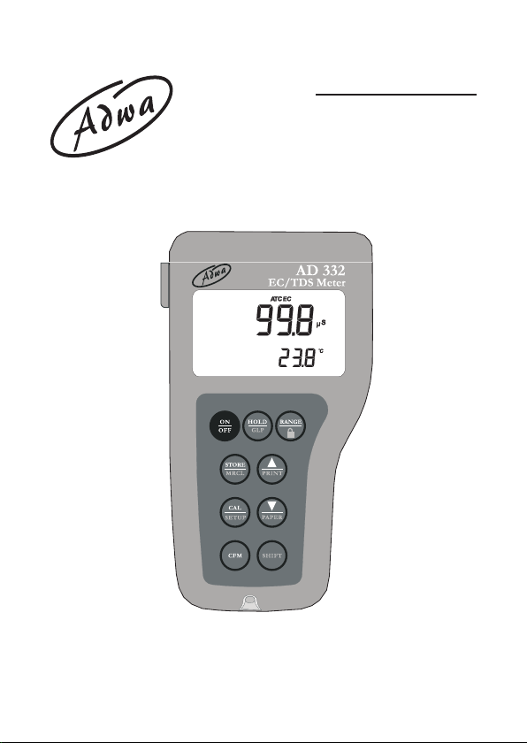
USER MANUAL
AD331 • AD332
Waterproof Portable Meters for
EC and TDS Measurements
www.adwainstruments.com
Page 2

Dear Customer,
Thank you for choosing an Adwa product.
Please read carefully this manual before starting operations.
This instrument is in compliance with the EMC directive 2004/
108/EC and its standards, and Low Voltage Directive 2006/95/
EC and its standards for electrical equipments.
For additional technical information, please e-mail us at
[email protected].
WARRANTY
Adwa warrants this product to be free of defects in material
and workmanship as stated in the operating manual. If repair
or adjustment is necessary and has not been the result of
abuse, misuse or improper handling within the warranty period, please contact your dealer or the nearest Adwa Office for
the RGA (Return Goods Authorization) number to put on the
outside of your package. Warranted service will be made without charge. The meter is warranted for a period of 2 years,
while probes are warranted for 6 months. The warranty period commences from the original date of sale. Warranty is
only valid when the product is used under normal conditions
and in accordance with the instruction manual. The warranty
is void if the instrument is repaired or serviced by unauthorized personnel, not used in accordance to the instructions,
or if non-Adwa accessories such as buffer solutions, probes,
etc. are used in conjunction with the meter. Adwa will not be
held responsible for any accident whether directly or indirectly, caused by the use of this instrument.
2
Page 3

TABLE OF CONTENTS
Introduction ................................................................ 4
Technical Data .......................................................... 6
Front and Top Panels ................................................ 8
Operational Guide .................................................... 10
Autoranging ............................................................. 14
Temperature Compensation .................................... 15
EC Calibration ......................................................... 17
Temperature Adjustment ........................................ 22
Setup ........................................................................ 23
Good Laboratory Practice ....................................... 26
Log-on-Demand ....................................................... 29
Hold Function .......................................................... 33
Printing
PC interface
Battery Replacement .............................................. 37
Probe Maintenance ................................................. 38
Probes and Solutions ............................................... 39
(AD332 only) ............................................................ 34
(AD332 only) .................................................. 36
3
Page 4

INTRODUCTION
AD331 and AD332 are waterproof portable meters.
AD331 reads EC in 5 ranges and AD332 can measure
EC and TDS. Both models also read temperature.
The autoranging feature of the EC and TDS ranges
automatically sets the instrument to the scale with the
highest resolution.
Measurements are compensated for temperature effect automatically (ATC) or manually (MTC). It is
also possible to disable the temperature compensation
feature to measure the actual conductivity.
The temperature coefficient is user selectable.
These instruments also feature a measurement stability indicator, GLP capability, and a user selectable ID
code to uniquely identify the instrument.
Moreover, AD332 includes PC interface and printing
function. Connect the meter to an external serial printer
with the following printer specifications:
• at least 16 characters / line
• baud rate 9600
• 9-pin RS232 input
4
Page 5

All models are supplied complete with:
• AD76309 conductivity probe with built-in tempera-
ture sensor and 1 m cable
• Calibration solution (20 ml sachet each):
• 1413 μS/cm EC standard solution
• 12,88 mS/cm EC standard solution
• 1.5 V AA alkaline batteries (4 pcs)
• User manual
5
Page 6

TECHNICAL DATA
EC Range 19.99 ; 199.9 ; 1999 μS/cm
19.99 ; 199.9 mS/cm
TDS Range 9.99 ; 99.9 ; 999 ppm
(AD332) 9.99 ; 99.9 ppt
Temperature Range -9.9 to 120.0 °C
Resolution 0.01 ; 0.1 ; 1 μS/cm
0.01 ; 0.1 mS/cm
0.01 ; 0.1 ; 1 ppm / 0.01 ; 0.1 ppt
0.1°C
Accuracy ±1% f.s. (EC and TDS)
(@20°C/68°F) ±0.5 °C
EC Calibration Offset: 0.0 μS/cm;
Slope: 1 point with 6
memorized standards (84.0, 1413 μS/cm; 5.00,
12.88, 80.0, 111.8 mS/cm) or one custom value
Temperature Automatic or manual,
Compensation -9.9 to 120 °C
Temperature Selectable
Coefficient from 0.00 to 10.00% / °C
6
Page 7

TDS Factor Selectable from 0.40 to 1.00
(AD332 only) (default value: 0.50)
Reference Temperature
Selectable from 15.0 to 30.0 °C
Log-on-demand Up to 250 samples
Probe (included) AD76309
PC Interface & Printer
(AD332 only)
RS232 port; external serial printer
Battery Type 4 x 1.5 V AA alkaline batteries
Battery Life Approx. 200 h of continuous use
Auto-Off User selectable: 5 min or disabled
Environment 0 to 50°C; RH max 95%
Dimensions 188 x 96 x 70 mm
Weight 460 g
7
Page 8
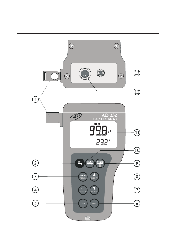
FRONT AND TOP PANELS
8
Page 9

1. Probe holder
2. ON/OFF key, to turn the instrument ON and OFF
3. STORE/MRCL key, to store the measured data
and to recall stored data
4. CAL/SETUP key, to enter/exit calibration and setup
mode
5. CFM key, to confirm values
6. SHIFT key, to activate the key alternate function
Press and hold first the SHIFT key and then the
second desired key
7. Down arrow/PAPER key, to manually decrease the
value of temperature or other parameters and to pull
out the printer paper
8. Up arrow/PRINT key, to manually increase the
value of temperature or other parameters and to obtain a printout or cancel printing
9. RANGE (
AD332) or NEXT (AD331)/“lock” key, to
select measurement unit or switch the focused data,
and to freeze current range on the LCD
10. HOLD/GLP key, to freeze the first stable reading
on the LCD and to display Good Laboratory Practice information
11. Liquid Crystal Display (LCD)
12. DIN connector for conductivity probe
13. RS232 port for serial printer or PC connection
9
Page 10
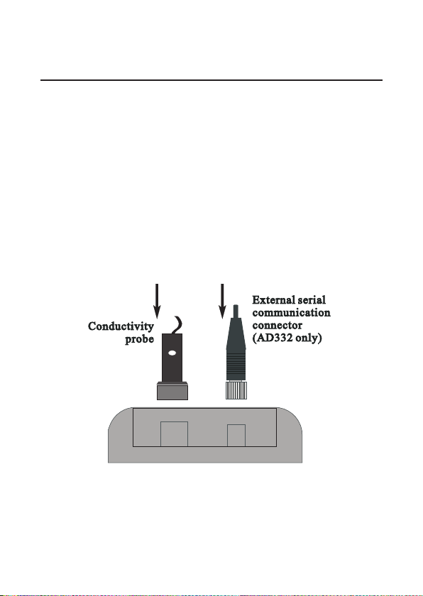
OPERATIONAL GUIDE
• The meter is supplied complete with four 1.5 V AA
alkaline batteries. Remove the battery cover, unwrap
the batteries and install them while paying attention to
their polarity (see “Battery Replacement” section for
details).
• Connect the supplied probe to the DIN connector and
tighten the threaded ring. Make sure the probe sleeve
is properly inserted.
10
Page 11
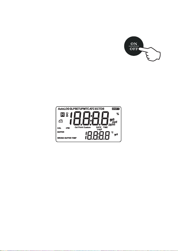
INSTRUMENT START-UP
• Turn the instrument on by pressing
the ON/OFF key.
• At start-up the display will show all used segments for
a few seconds (or while the button is held), followed
by the reference temperature value with “rEF” indication, then enters the measurement mode.
• To save battery life, the auto-off feature automatically
turns the meter off after 5 minutes with no button
pressed. This feature can be disabled through the
“AoFF” setup item (see “Setup” section for details).
11
Page 12
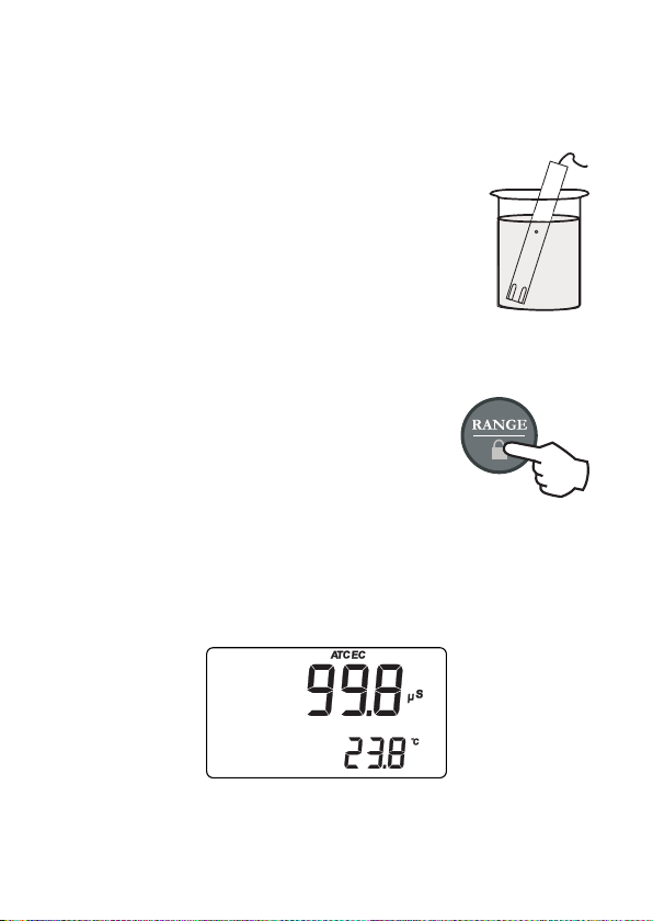
TAKING MEASUREMENTS
• Immerse the probe into the solution
to be tested. The sleeve holes must
be completely submerged.
• Tap the probe repeatedly to remove
any air bubbles that may be trapped
inside the sleeve.
• If needed, press RANGE (AD332)
until the EC or TDS range is selected
on the LCD.
• Allow for the reading to stabilize. The primary LCD
displays the measurement in the selected range, while
the secondary LCD shows the temperature reading.
12
Page 13

Notes:
• If the meter displays only dashes "----", the read-
ing is out of range.
• If the stability indicator (hourglass symbol) blinks,
the reading is not stable.
• Make sure the meter is calibrated before taking
measurements.
• If measurements are taken successively in dif-
ferent samples, for accurate reading it is recommended to rinse the probe thoroughly with deionized water before immersing it into the next
sample.
• For AD332: the TDS reading is obtained by mul-
tiplying the EC value by the TDS factor (default: 0.50). This factor can be selected by the
user (0.40 to 1.00) through the "tdS" setup item
(see “Setup” section for details).
13
Page 14
AUTORANGING
The EC and TDS scales are autoranging. The meter
automatically sets the scale with the highest possible
resolution.
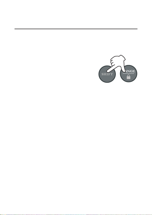
By pressing SHIFT and “lock” keys,
the autoranging feature is disabled
and the current range is frozen on
the LCD.
The μS, mS, ppm or ppt tag (depend-
ing on the selected measurement
mode and range) starts blinking.
To restore the autoranging option press the SHIFT and
“lock” keys again.
Note: Autoranging is automatically restored if range is
changed, if setup or calibration mode is entered,
or if meter is turned off and back on again.
14
Page 15

TEMPERATURE COMPENSATION
Three options are available for temperature compensation:
1. Automatic (ATC): the EC probe features a built-in
temperature sensor, which allows automatic compensation of the EC or TDS measurements.
2. Manual (MTC): the temperature value can be manu-
ally set using the arrow keys. The compensation is
referenced to the selected reference temperature.
While in MTC mode, the °C tag blinks on the secondary LCD.
3. No compensation (No TC): the temperature is not
taken into account. The reading displayed on the primary LCD is the actual EC or TDS value.
Notes:
• The default compensation mode is ATC.
• Temperature compensation setting can be accessed through the "tcE" setup item (see “Setup”
section for details).
• If the temperature compensation is active, measurements are compensated using the temperature coefficient (default value 1.90 %/°C).
15
Page 16

The temperature coefficient can be modified
through the “tc” setup item (see “Setup” section
for details).
• If the temperature reading is out of the -9.9 to
120.0°C range and the ATC option is selected,
the temperature full scale value and the °C tag
will blink on the secondary LCD.
• The reference temperature can be set from 15
to 30°C. When the reference temperature is
changed, the temperature coefficient must be
manually adjusted by the user.
For example, if α is the coefficient with refer-
ence temperature of 25°C, when changing the
temperature to 20°C, the new coefficient can
be calculated with the following formula:
β=α/(1-α/20)
If α=1.90%/°C, then β=2.10%/°C.
• For AD332, always set reference tempera-
ture to 25°C when measuring TDS.
16
Page 17
EC CALIBRATION
EC calibration is performed for both meters. For AD332,
since the TDS values are automatically derived from
the EC readings, no specific calibration for TDS is needed.
Selectable points for EC calibration are 0.00, 84.0 and
1413 μS/cm, 5.00, 12.88, 80.0 and 111.8 mS/cm.
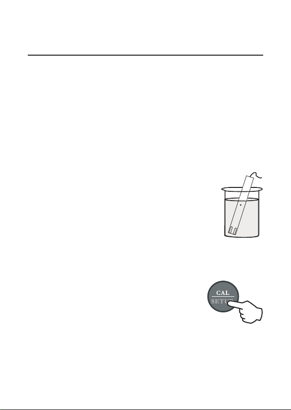
• Rinse the probe with selected standard or deionized
water, then immerse it into the calibration solution. The sleeve holes
must be completely submerged.
• Tap the probe repeatedly to remove
any air bubbles that may be trapped
inside the sleeve.
• To enter calibration mode, press the CAL key from
the corresponding measurement range.
Note: For AD332, pressing CAL
when TDS range is selected
has no effect.
17
Page 18
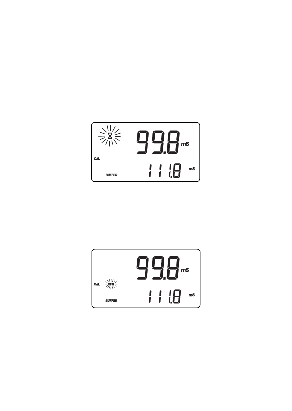
• For zero calibration, simply leave the dry probe in the
air. The "CAL" and "BUFFER" tags light up.
• The primary LCD displays the not calibrated EC or
TDS reading, while the secondary LCD shows one of
the available standard values. The hourglass symbol
blinks.
• If necessary, use the arrow keys to select the desired
standard value.
• When the reading is stable, the CFM tag starts blinking. Press CFM to confirm calibration.
• The instrument displays the "Stor Good" message and
returns to measurement mode.
18
Page 19

Notes:
• If the temperature is out of range, the "WRONG
BUFFER TEMP" message blinks on the LCD.
If the reading is too far from the expected value,
"WRONG BUFFER" blinks.
• For best results, use a calibration solution with
EC (or TDS) value close to the sample to be
measured.
• During calibration the meter compensates using
the 1.90%/°C coefficient. If the setup item "tc"
has been set to a different value, when exiting
calibration mode, the displayed value might be
different from the nominal standard value.
CUSTOM CALIBRATION
Calibration can be also performed with a custom calibration solution.
• Immerse the probe into the custom calibration solution
and select the proper EC (or TDS) range. Press first
CAL to enter the calibration mode and then RANGE
(or NEXT) to enter the custom calibration.
19
Page 20
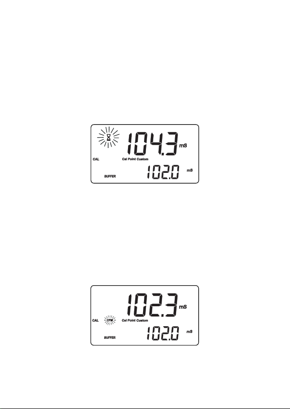
• The "CAL", "BUFFER" and "Cal Point Custom" tags
light up. The primary LCD displays the not calibrated
temperature compensated reading, while the secondary LCD shows the temperature compensated reading, factory calibrated with cell value k=1. The hourglass symbol blinks.
• Using the arrow keys, adjust the reading displayed on
the primary LCD to the desired value.
• The maximum adjustment is ±40% around the value
displayed on the secondary LCD.
• When the reading is stable, the CFM tag starts blinking. Press CFM to confirm calibration.
20
Page 21

• The instrument displays the "Stor Good" message and
returns to measurement mode.
Notes:
• Zero calibration is not allowed in custom mode.
• The calibrated custom value is considered the
value of the calibration solution at the selected
reference temperature.
• The cell constant value can be set directly through
the "CELL" setup item, without following the calibration procedure (see “Setup” section for details).
• Temperature reading is not used during custom
calibration.
21
Page 22
TEMPERATURE ADJUSTMENT
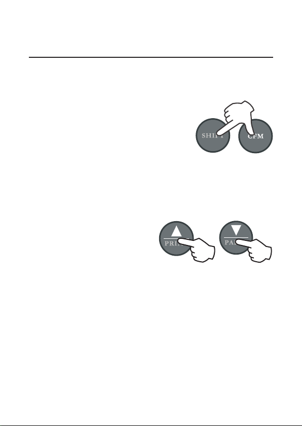
Temperature reading can be manually fine-tuned as explained in this section.
Press SHIFT and CFM keys to enter
the temperature adjustment mode.
Both primary and secondary LCDs
will display the current temperature
reading for a few seconds, followed
by the default temperature reading.
Adjust the temperature value on the primary LCD using
the arrow keys. The maximum allowed adjustment is
±1.0
ºC around the current reading.
Press CFM to confirm. The meter returns to measurement mode and displays the new temperature.
Notes:
• Press SHIFT and CFM keys to escape without
changing.
• To enter temperature adjustment mode, the
probe must be connected and the meter must
be in ATC mode.
22
Page 23
SETUP
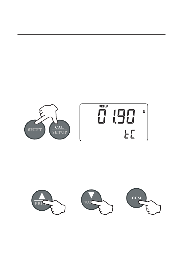
Setup mode allows to view and modify the instrument
parameters.
To enter setup mode, press SHIFT and then SETUP
key from measurement mode. The SETUP tag lights
up. The primary LCD will display the temperature coefficient (default value 1.90%/
LCD shows the code of the current setup item.
Select the desired setup item using the arrow keys, then
press CFM to select and edit the setup item. The current value of the selected item starts blinking (if the parameter can be modified).
ºC), while the secondary
23
Page 24
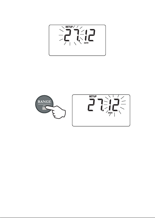
Use the arrow keys to change the value.
If there is another part of the item to be set (e.g. month
in setting up the current date), press RANGE (or NEXT)
and the part to be changed will start blinking.
Use the arrow keys to change the value and then press
CFM to confirm.
Note: To escape without changing the previously set
value, press SHIFT and then SETUP before
confirming.
24
Page 25
The following table lists the setup items, their valid range
and the factory settings (default):
Item
tc
tcE
rEF
tdS
CELL
AoFF
YEAr
DATE
TIME
id
vEr
(*) For AD332 only.
Description
Temperature coefficient
Temp.compensation mode
Reference temperature
TDS factor (*)
Cell constant (K)
Auto-off feature
Printer Status (*)
Year
Date (DD.MM)
Time (hh:mm)
Meter identification code
Firmware release
Valid values Default
0.00 to 10.00% / ºC 1.90
Atc, Mtc, notc Atc
15.0 to 30.0 ºC 25.0 ºC
0.40 to 1.00 0.50
0.500 to 1.700 1.000
On, Off Off
On/Off Off
2000 to 2098 2000
01.01 to 31.12 01.01
01:01 to 23:59 00:00
0000 to 9999 0000
25
Page 26
GOOD LABORATORY PRACTICE
Good Laboratory Practice (GLP) is a set of functions
that allows storage and retrieval of data regarding the
status of the system.
After a successful calibration, the meter automatically
stores the date and time of calibration, the used calibration solution and the resulting cell constant value.
All this information can be recalled by the user.
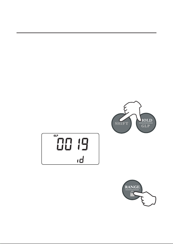
To view the last calibration data,
press SHIFT and then GLP keys.
The first information appearing on
the LCD is the meter "id" code.
By repeatedly pressing RANGE
(or NEXT) key, all GLP data are
displayed as shown in the next
pages.
26
Page 27
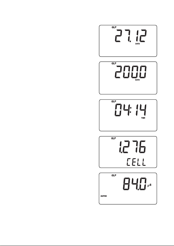
Last calibration date (day and
month).
Last calibration date (year).
Last calibration time.
Cell constant (K)
Calibration with standard solution.
27
Page 28

Calibration with custom solution.
If the cell constant was changed after calibration (through
the “CELL” setup item), this information is not displayed.
If RANGE (or NEXT) is pressed while the last parameter is displayed, the meter returns to measurement mode.
Notes:
• To exit GLP mode at any time, press SHIFT+GLP.
• If calibration has never been performed, after displaying the ID code, the meter will show the "no CAL"
message blinking. Press RANGE (or NEXT) or
SHIFT+GLP to return to measurement mode.
•For AD332, only last EC calibration data are avail-
able. No calibration data can be recalled for TDS. If
SHIFT+GLP are pressed from TDS measurement
mode, the meter will display the ID code only. Press
SHIFT+GLP again to return to measurement mode.
• GLP data are not affected by zero calibrations.
28
Page 29
LOG-ON-DEMAND
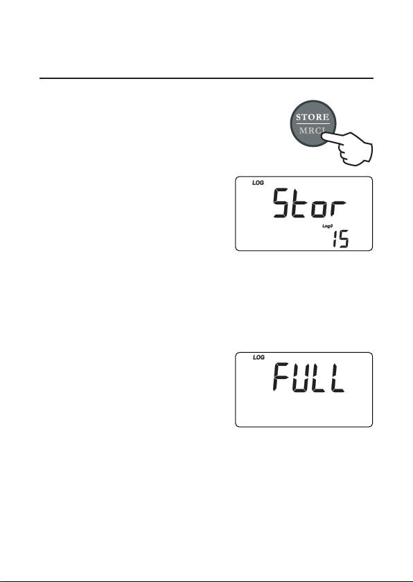
To store current reading into memory,
press STORE key from measurement
mode.
The LCD will display for a
few seconds the "Stor" message together with the "Log"
tag and the sample number.
By pressing the STORE key a complete set of information is memorized: date, time, EC or TDS and temperature readings.
Up to 250 samples can be stored into memory.
When the memory is full and
the STORE key is pressed, the
sample will not be stored and
the LCD will display the
"FULL" message.
In this case, it is necessary to delete the last sample or
all logged data to proceed.
29
Page 30
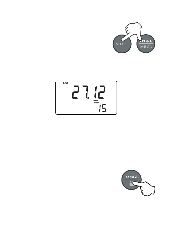
VIEWING STORED DATA
To retrieve memorized information,
press SHIFT and then MRCL keys.
The primary LCD displays the date (day & month) and
the secondary LCD shows the number of last stored
sample.
If no samples are stored into memory, the "ZERO" message is displayed.
• Select the desired sample number using the arrow keys.
If the up arrow key is pressed while the last sample is
displayed, the meter returns to the first sample.
• Press RANGE (or NEXT) to view
the remaining data for the selected
sample as shown in the next page.
30
Page 31
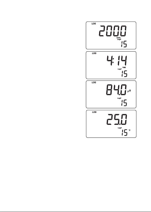
• Year
• Time
• EC or TDS reading (only
dashes "----" means reading
out of range or probe not
connected)
• Temperature reading (only
dashes "----" means reading
out of range)
• To skip to next or previous sample, use the up or down
arrow key respectively. For example, if the up arrow
key is pressed while a sample reading is displayed, the
meter shows the reading of next sample.
• To return to measurement mode, press SHIFT+MRCL
at any time.
31
Page 32
DELETING STORED DATA
The meter allows to delete a single sample or all the
memory at one time.
To delete a single sample proceed as follows:
• Enter the viewing stored data mode and select the desired sample number.
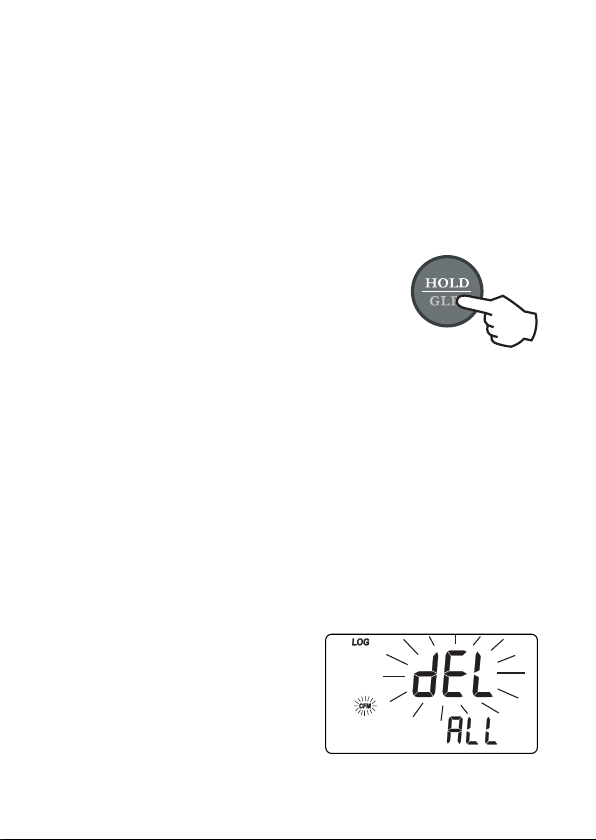
• Press the HOLD key. "dEL" and
"CFM" will start blinking.
• Press CFM to confirm deletion or HOLD again to
escape without deleting data. When scrolling through
stored data, if a deleted sample is selected, the meter
will display the "nuLL" message.
To delete all data in memory:
• Enter the viewing stored data mode.
• Press SHIFT+HOLD keys. "dEL" and "CFM" will start
blinking and the "ALL" message is displayed on the
secondary LCD.
32
Page 33
• Press CFM to confirm deletion or SHIFT+HOLD
again to escape without deleting data.
Note: If no samples are stored in memory and a dele-
tion is attempted, the meter shows the "Zero"
message and then returns to measurement mode.
HOLD FUNCTION
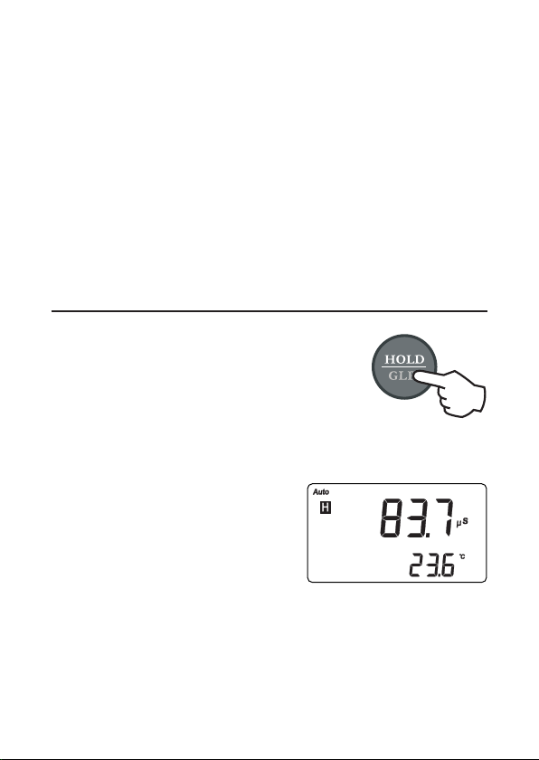
To freeze the first stable reading on
the LCD, press the HOLD key from
measurement mode.
The “Auto” and “H” tags will blink on the LCD until the
reading is stabilized.
When the reading becomes
stable, the “Auto” and “H”
tags stop blinking and the reading is frozen.
Press the HOLD key again to return to normal measurement mode.
33
Page 34

PRINTING (AD332 only)
When connected to an external serial printer, a complete set of information can be printed. Use the AD9551
serial communication cable (optional).
Printer specifications:
• at least 16 characters / line
• baud rate 9600
• 9-pin RS232 input
Data can be printed on demand (from measurement, GLP
and SETUP modes) by pressing SHIFT+PRINT keys,
or automatically for log-on-demand mode.
Note: To cancel printing, press SHIFT+PRINT again.
While in EC measurement mode, the printout provides
the following information.
Date 2000/01/01
Time 00:19
EC 83.2 mS
°C 25.0
Note: For TDS measurement mode, the TDS reading
will be printed.
34
Page 35
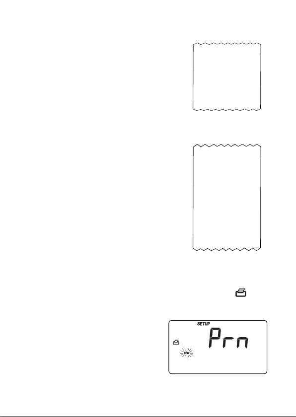
When in GLP mode, the printout provides the following information:
GL P
Instr ID 0005
Date 2000/01/01
Time 00:34
Cell 0.961
Cal Buffer
EC 8.00 mS
When in SETUP mode, the following information are printed:
SETUP REPORT
Instr ID 0005
Date 2000/01/01
Time 00:34
TC 01.90 %
TCE Atc
Temp REF 25.0
TDS Factor 0.50
Cell 1.000
AutoOff OFF
Printer On
Version 1.0
When exiting the setup mode, the instrument asks if the
setup report has to be printed. The “Prn” message will
be displayed together with the printer symbol ( ) and
the CFM tag blinking.
35
Page 36

Press CFM to print the setup report or CAL to exit without printing.
When a reading is logged on-demand,
an automatic printout will provide the
following information for EC or TDS:
LO G
Record No 001
Date 2000/01/01
Time 00:19
EC 83.2 mS
°C 25.0
PC INTERFACE (AD332 only)
Data transmission from the instrument to the PC can be
done with the ADSW10 Windows® compatible software
(optional). ADSW10 offers graphing and on-line help
feature, and data can be exported to the most popular
spreadsheet programs for further analysis.
To connect the instrument to a PC, use the AD9551
serial communication cable (optional). Make sure that
the instrument is switched off and plug the cable to the
instrument RS232 socket and to the PC serial port.
Specifications:
Isolated 8-bit data transmission
Baud rate: 2400
Start bit: 1
Stop bit: 1
Parity bit: none
36
Page 37
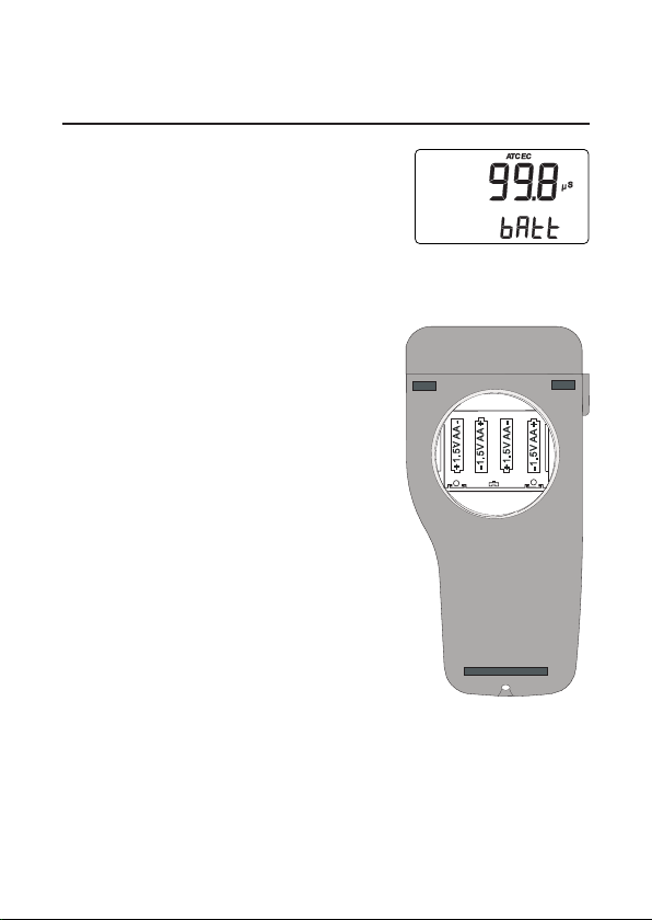
BATTERY REPLACEMENT
When batteries become too
weak, the “bAtt” message appears. It is recommended to replace the batteries soon.
When the battery level is too low to ensure reliable readings, the meter automatically turns off.
Battery replacement must only
take place in a safe area and using the battery type specified in
this instruction manual.
To replace rundown batteries, remove the battery cover and substitute all four 1.5 V AA alkaline
batteries with new ones, while
paying attention to the correct polarity.
Reattach and tighten the battery
cover making sure that the gasket is in place.
Note: When batteries are removed, the meter can re-
member date & time for about 5 minutes. After
that, it will be necessary to set again date & time
through the setup procedure.
37
Page 38
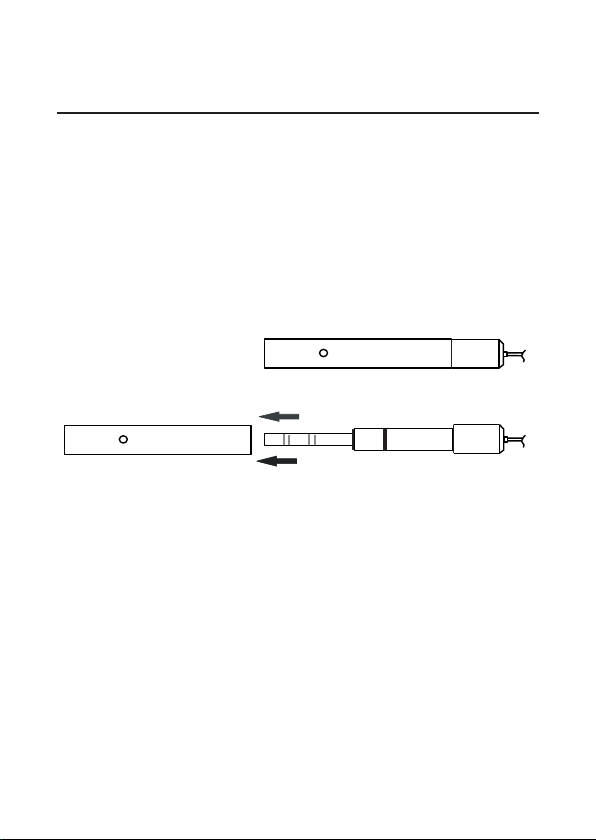
PROBE MAINTENANCE
After measurements, rinse the probe with clean water.
If a more thorough cleaning is required, remove the probe
sleeve and clean the probe with a cloth or a non-abrasive detergent.
Make sure to reinsert the sleeve onto the probe properly
and in the right direction.
After cleaning the probe, recalibrate the instrument.
38
Page 39

PROBES AND SOLUTIONS
AD76309 Conductivity probe with built-in tem-
perature sensor, DIN connector and 1 m
cable
AD70030P 12.88 mS/cm EC solution, 20 ml sachet,
25 pcs
AD7030 12.88 mS/cm EC standard solution, 230
ml bottle
AD70031P 1413 μS/cm EC standard solution, 20 ml
sachet, 25 pcs
AD7031 1413 μS/cm EC standard solution, 230
ml bottle
AD7033 84 μS/cm solution, 230 ml bottle
AD7034 80.00 mS/cm EC standard solution, 230
ml bottle
AD7035 111.80 mS/cm EC standard solution, 230
ml bottle
AD7039 5000 μS/cm EC standard solution, 230
ml bottle
AD70442 1500 ppm TDS standard solution, 230
ml bottle
AD9551 Serial communication cable
39
Page 40

ADWA HUNGARY Kft.
Alsókikötõ sor 11, 6726 Szeged, Hungary
Tel. +36 62 317 878
Fax +36 62 550 610
www.adwainstruments.com
MANAD331 09/14
 Loading...