

Page 1
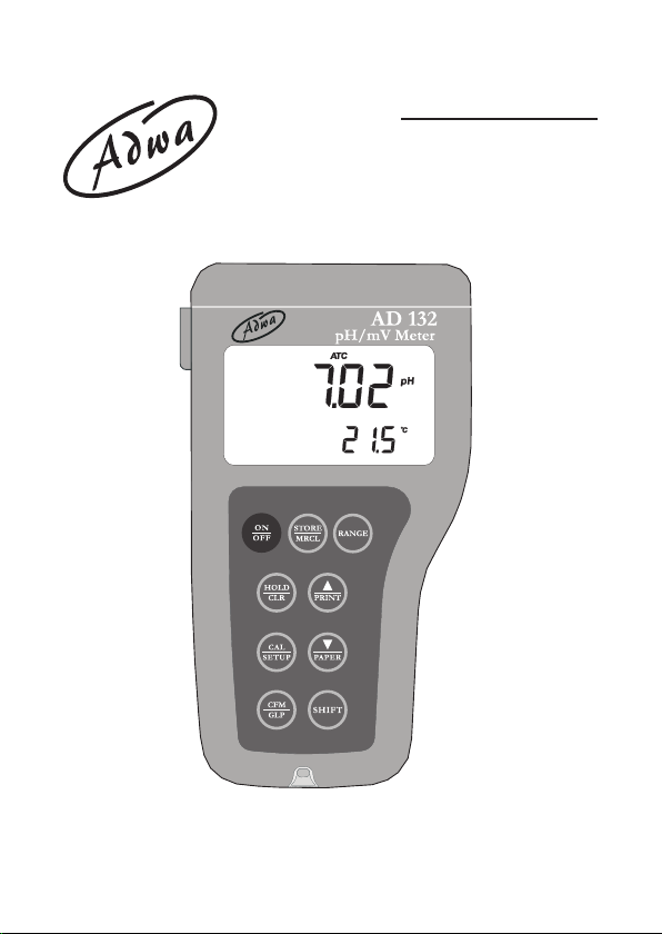
USER MANUAL
AD 131 and AD 132
pH/mV/Temperature
Waterproof Meters
www.adwainstruments.com
Page 2

Dear Customer,
Thank you for choosing an Adwa product.
Please read carefully this manual before starting operations.
This instrument is in compliance with the EMC directive 2004/
108/EC and its standards, and Low Voltage Directive 2006/95/
EC and its standards for electrical equipments.
For additional technical information, please e-mail us at
[email protected].
WARRANTY
Adwa warrants this product to be free of defects in material
and workmanship as stated in the operating manual. If repair
or adjustment is necessary and has not been the result of
abuse, misuse or improper handling within the warranty
period, please contact your dealer or the nearest Adwa Office
for the RGA (Return Goods Authorization) number to put on
the outside of your package. Warranted service will be made
without charge. The meter is warranted for a period of 2 years,
while probes are warranted for 6 months. The warranty
period commences from the original date of sale. Warranty is
only valid when the product is used under normal conditions
and in accordance with the instruction manual. The warranty
is void if the instrument is repaired or serviced by unauthorized
personnel, not used in accordance to the instructions, or if
non-Adwa accessories such as buffer solutions, probes, etc.
are used in conjunction with the meter. Adwa will not be held
responsible for any accident whether directly or indirectly,
caused by the use of this instrument.
2
Page 3

TABLE OF CONTENTS
Introduction ................................................................ 4
Technical Data .......................................................... 6
Front and Top Panels ................................................ 8
Operational Guide .................................................... 10
pH Calibration ......................................................... 16
Relative mV Calibration .......................................... 25
Good Laboratory Practice (GLP) ........................... 26
Setup ........................................................................ 31
Log-on-demand ........................................................ 34
Hold Function .......................................................... 39
Printing (AD132 only) ............................................. 40
Battery Replacement .............................................. 44
Temperature Calibration
mV Calibration
(for technical personnel only) .................. 47
PC Interface (AD132 only) .................................... 49
pH Electrode Conditioning & Maintenance ........... 50
Troubleshooting Guide ............................................. 52
Electrodes, Probes and Solutions ............................ 54
(for technical personnel only) 45
3
Page 4

INTRODUCTION
AD131 and AD132 are heavy-duty portable waterproof
meters for pH, ORP (Oxidation Reduction Potential) and
temperature measurements, designed to provide laboratory
results and accuracy even under harsh industrial conditions.
Main features include:
• 7 memorized buffers for pH calibration (pH 1.68, 4.01,
6.86, 7.01, 9.18, 10.01 and 12.45)
• Messages on the LCD to make the calibration easy
and accurate
• pH readings with manual or automatic temperature
compensation
• Calibration time-out alarm
• Log-on-demand
• HOLD feature to freeze stable reading on the LCD
• GLP feature to view last calibration data for pH and
relative mV
• PC interface (AD132 only)
4
Page 5

• Connection to an external serial printer (AD132 only)
with the following specification:
• at least 16 characters/line
• baud rate 9600
• 9-pin RS232 input
Both models are supplied complete with:
• AD1230B pH electrode with double ceramic junction,
BNC connector and 1 m cable
• AD7662 stainless steel temperature probe, 1 m cable
• 1.5V AA alkaline batteries (4 pcs)
• User manual
5
Page 6

TECHNICAL DATA
Range -2.00 to 16.00 pH
±2000 mV
-20.0 to 120.0 °C (-4.0 to 248.0 °F)
Resolution 0.01 pH
0.1 mV (±999.9 mV) / 1 mV (outside)
0.1 °C (0.1 °F)
Accuracy ±0.01 pH
(@25 °C/77 °F) ±0.2 mV up to ±699.9 mV
±0.5 mV up to ±999.9 mV
±2 mV (outside)
±0.4 °C (±0.7 °F) excluding probe error
Relative mV Offset ± 2000 mV
pH Calibration Up to 5-point calibration,
with 7 standard buffers
(pH 1.68, 4.01, 6.86, 7.01, 9.18, 10.01, 12.45)
Temperature Manual or automatic,
Compensation -20.0 to120.0 °C (-4.0 to 248.0 °F)
pH Electrode AD1230B
Temperature Probe AD7662
Log-on-demand 500 samples
Printer (AD132 only) External serial printer
6
Page 7

PC Interface (AD132 only) RS232 port
Input Impedance 1012 Ohm
Environment 0 to 50 °C (32 to 122 °F)
RH max. 100% non-condensing
Power Supply 4 x 1.5 V AA, alkaline battery
Battery Life Approx. 300 hours of continuous use
Auto-off User selectable: 5 minutes or disabled
Dimensions 188 x 96 x 70 mm
Weight 460 g
7
Page 8
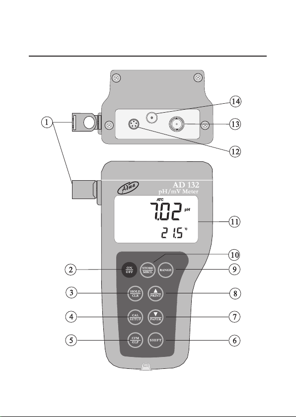
FRONT AND TOP PANELS
8
Page 9

1. Holders for probes
2. ON/OFF key, to turn the instrument ON and OFF
3. HOLD/CLR key, to freeze stable reading on the
LCD and clear calibration or logged data
4. CAL/SETUP key, to enter/exit calibration mode or
enter/exit SETUP mode
5. CFM/GLP key, to confirm value and display GLP
information
6. SHIFT key, to activate the key second function.
Press first SHIFT and then the selected key. The
SHIFT tag is displayed until the second key is pressed
7. DOWN arrow/PAPER (PAPER for AD132 only)
to manually decrease the value of temperature or
other parameters, or to pull out printer paper
8. UP arrow/PRINT (PRINT for AD132 only) key, to
manually increase the value of temperature or other
parameters, to obtain a printout or cancel printing
9. RANGE key, to select measurement range or switch
focused data
10. STORE/MRCL key, to store measured data and
enter/exit the logged data viewing mode
11. Liquid Crystal Display (LCD)
12. RS232 connector (AD132 only)
13. BNC connector for pH or ORP electrodes
14. Temperature probe socket
9
Page 10
OPERATIONAL GUIDE
• The meter is supplied complete with four 1.5V AA
alkaline batteries. Remove the rear cover, unwrap the
batteries and install them while paying attention to the
correct polarity (see “Battery Replacement” section).
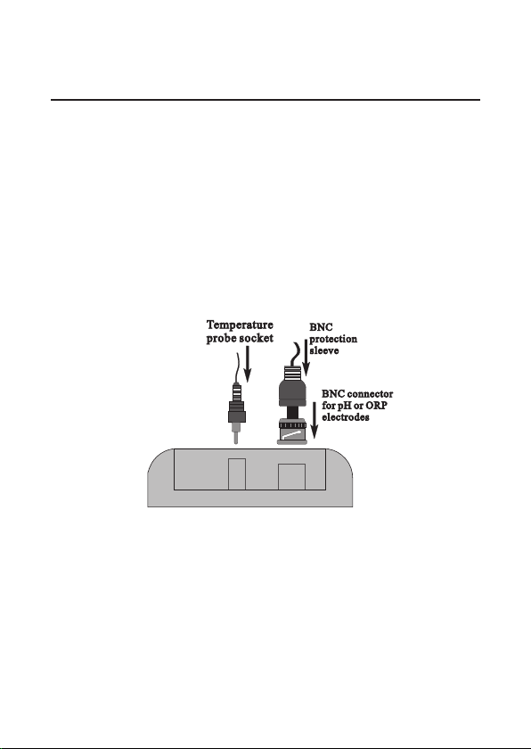
• Connect pH electrode and temperature probe to the
BNC and temperature sockets on the top of the
instrument. Slide the BNC protection sleeve to
completely cover the BNC connector.
• The temperature probe is used in conjunction with the
pH electrode to utilize the meter’s ATC capability, but
it can also be used independently to take temperature
measurements. If the probe is disconnected, the
temperature can be set manually using the arrow keys.
10
Page 11
INSTRUMENT START-UP
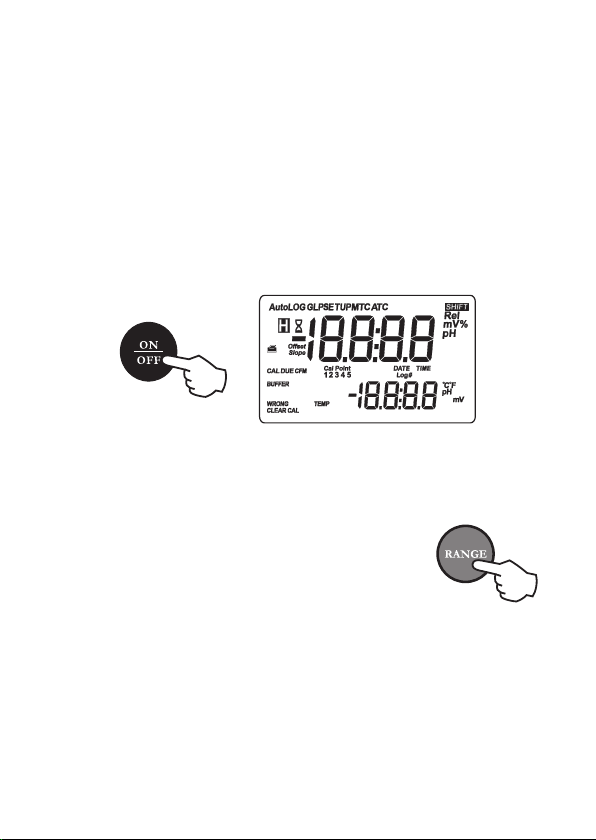
• Turn the instrument on by pressing ON/OFF.
• At start-up the display shows all the used segments
for a few seconds (or while the button is held),
followed by date and time, then enters the measurement
mode.
pH MEASUREMENTS
Make sure the instrument has been calibrated before
taking pH measurements.
• If necessary, press RANGE to enter the
pH mode.
• Remove the electrode tip protection bottle. Submerge
the pH electrode tip (4 cm) and the temperature probe
into the sample to be tested.
• Allow a few seconds for the electrode to stabilize.
11
Page 12
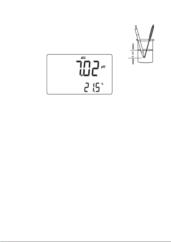
• The pH reading is displayed on the primary
LCD and the temperature on the
secondary LCD.
• If measurements are taken successively in different
samples, it is recommended to rinse the electrode
thoroughly with deionized or tap water. Then to condition
the electrode, rinse it with some of the next sample to
be measured before immersing it into the solution.
• Since the pH reading is affected by temperature, in
order to measure the pH accurately, the meter is provided
with temperature compensation feature. To use the
automatic temperature compensation (ATC) feature,
connect and immerse the
into the sample as close as possible to the electrode
and wait for a few seconds.
AD7662 temperature probe
12
Page 13
• If the temperature of the sample is known, manual
temperature compensation (MTC) can be performed.
Disconnect the temperature probe and the display will
show the default temperature of 25 °C
last temperature reading with the °C (or °F) tag blinking.
• The temperature value can be adjusted using the arrow
keys.
ORP (mV) MEASUREMENTS
Oxidation- reduction potential (REDOX) measurements
provide the quantification of the oxidizing or reducing
power of the tested sample.
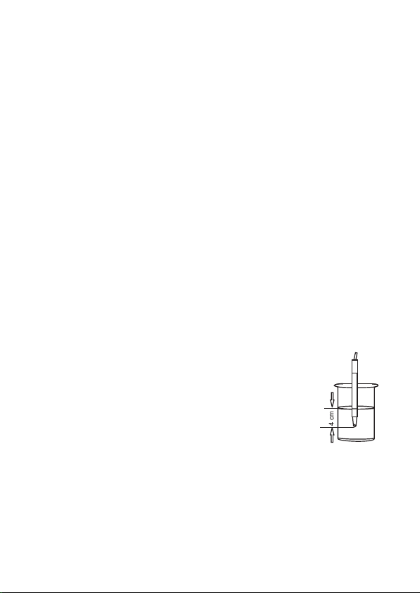
To correct perform a redox measurement, the surface
of the ORP electrode must be clean and smooth.
•
Press RANGE to enter the mV mode.
(77 °F) or the
• Immerse the tip of the ORP electrode at
least 4 cm into the solution to be tested
and wait a few seconds for the reading to
stabilize.
• The instrument displays the mV reading on the primary
LCD and the temperature on the secondary LCD.
13
Page 14
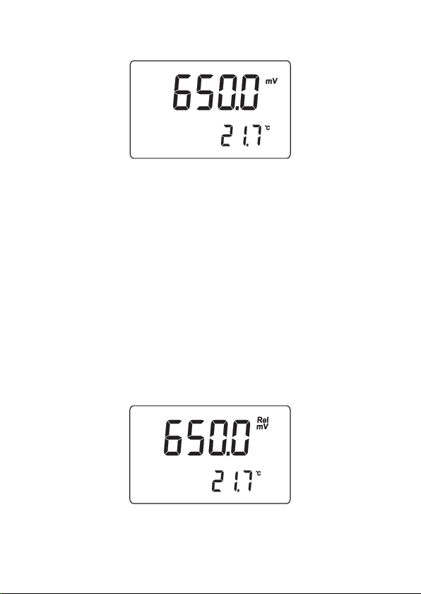
• If the reading is out of range, the closest full-scale
value will be displayed blinking on the primary LCD.
RELATIVE mV MEASUREMENTS
To enter the relative mV mode, press the RANGE key.
The relative mV reading will be displayed on the
primary LCD and the current temperature value on the
secondary LCD.
The relative mV reading is equal to the difference
between the absolute mV input value and relative mV
offset established in the relative mV calibration.
14
Page 15

TEMPERATURE MEASUREMENTS
Connect the
AD7662 temperature probe
to the appropriate socket. Immerse the
temperature probe into the solution and
allow the reading to stabilize.
Notes:
• The temperature can be displayed in Celsius (°C)
or Fahrenheit (°F) degrees (see “Setup” section
for details).
• Make sure that the temperature probe is
immersed in the same sample that is measured.
15
Page 16

pH CALIBRATION
The instrument should be recalibrated:
• Whenever the pH electrode is replaced
• At least once a week
• After testing aggressive chemicals
• If the “CAL DUE” message blinks during measurement
PREPARATION
Pour small quantities of the buffer solutions into clean
beakers. If possible, use plastic beakers to minimize any
EMC interferences.
For accurate calibration, use two beakers for each buffer
solution: the first one for rinsing the electrode and the
second for calibration.
If you are measuring in the acidic range, use pH 4.01 or
1.68 as second buffer. If you are measuring in the alkaline
range, use 10.01/9.18 or 12.45 as second buffer.
For extended range measurements (acidic and alkaline),
perform a five-point calibration by selecting five of the
available buffers.
16
Page 17

PROCEDURE
The meter allows to choose among 7 memorized buffer
values: pH 1.68, 4.01, 6.86, 7.01, 9.18, 10.01 and 12.45.
For accurate measurements it is recommended to
perform a five-point procedure. However, at least a
two-point calibration is suggested.
The instrument will automatically skip the buffers already
used and require a minimum difference of 0.2 pH unit
between two buffers used for calibration.
A new calibration will override existing stored calibration
data. The slopes adjacent to the calibration points will be
reevaluated.
If the new calibration point has no correspondence in
the existing stored calibration data, it is simply added or
the instrument will ask which buffer will be replaced by
the current one.
If at least a two-point calibration has been performed
and an offset correction of the electrode is desired, keeping
unchanged the existing slopes, perform a one-point
calibration selecting the “OFFS” option in the setup menu.
If the “Pnt” option is selected, the slopes adjacent to the
calibration points will be reevaluated.
17
Page 18
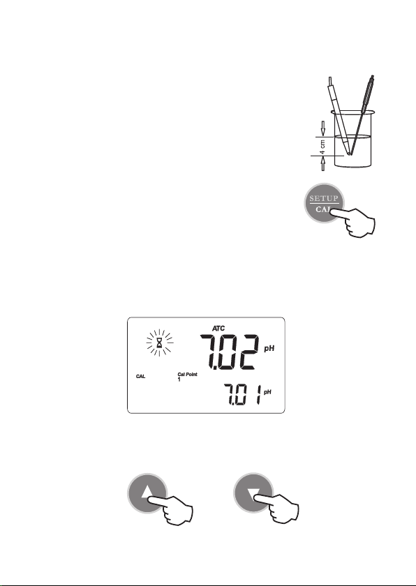
FIVE-POINT CALIBRATION
• Immerse the pH electrode and the
temperature probe approximately 4 cm
into the first buffer solution (pH 1.68,
4.01, 6.86, 7.01, 10.01 or 12.45) and stir
gently. The temperature probe should
be close to the pH electrode.
• To enter the pH calibration mode, press
CAL from pH measurement mode.
• The instrument will display the measured pH on the
primary LCD and the “7.01 pH” buffer on the
secondary LCD, together with “CAL” and “Cal Point
1” tags.
• If necessary, use the arrow keys to select a different
buffer value.
18
Page 19
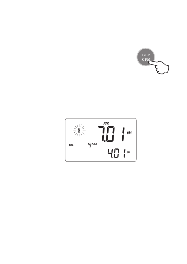
• The hourglass symbol will blink on the LCD until the
reading is stable.
• When the reading is stable and close
to the selected buffer, the “CFM” tag
blinks. Press the CFM key to confirm
calibration.
• The calibrated value is then displayed on the primary
LCD and the secondary LCD shows the second
expected buffer value, together with the “CAL” and
“Cal Point 2” tags.
Note: If the buffer is not recognized, the “WRONG”
message blinks to advise the user. Change buffer
and proceed.
• After the first calibration point is confirmed, immerse
the pH electrode and the temperature probe approximately
4 cm into the second buffer solution and stir gently.
The temperature probe should be close to the pH
electrode.
19
Page 20

• If necessary, use the arrow keys to select a different
buffer value.
• The hourglass symbol will blink on the LCD until the
reading is stable.
• When the reading is stable and close
to the selected buffer, the “CFM” tag
blinks (or “WRONG” for buffer not
recognized). Press the CFM key to
confirm calibration.
• The calibrated value is then displayed on the primary
LCD and the secondary LCD shows the third expected
buffer value.
• After the second calibration point is confirmed,
immerse the pH electrode and the temperature probe
approximately 4 cm into the third buffer solution and
stir gently. The temperature probe should be close to
the pH electrode.
• If necessary, use the arrow keys to select a different
buffer value.
• The hourglass symbol will blink on the LCD until the
reading is stable.
• When the reading is stable and close to the selected
buffer, the “CFM” tag blinks (or “WRONG” for buffer
20
Page 21
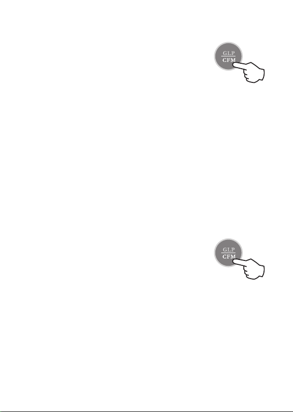
not recognized). Press the CFM key to
confirm calibration.
• The calibrated value is then displayed
on the primary LCD and the secondary
LCD shows the fourth expected buffer
value.
• After the third calibration point is confirmed, immerse
the pH electrode and the temperature probe approximately
4 cm into the third buffer solution and stir gently. The
temperature probe should be close to the pH electrode.
• If necessary, use the arrow keys to select a different
buffer value.
• The hourglass symbol will blink on the LCD until the
reading is stable.
• When the reading is stable and close
to the selected buffer, the “CFM” tag
blinks (or “WRONG” for buffer not
recognized). Press the CFM key to
confirm calibration.
• The calibrated value is then displayed on the primary
LCD and the secondary LCD shows the fifth expected
buffer value.
21
Page 22

• After the fourth calibration point is confirmed, immerse
the pH electrode and the temperature probe approximately
4 cm into the third buffer solution and stir gently. The
temperature probe should be close to the pH electrode.
• If necessary, use the arrow keys to select a different
buffer value.
• The hourglass symbol will blink on the LCD until the
reading is stable.
• When the reading is stable and close
to the selected buffer, the “CFM” tag
blinks (or “WRONG” for buffer not
recognized). Press the CFM key to
confirm calibration.
• The instrument stores the calibration values and
returns to normal measurement mode.
FOUR, THREE or TWO-POINT CALIBRATION
Proceed as described in the “Five-point calibration” section
and press CAL after the appropriate accepted calibration
point. The instrument will memorize the calibration data
and return to normal measurement mode.
22
Page 23

ONE-POINT CALIBRATION
• Two setup options are available: “Pnt” and “OFFS”.
• If the “Pnt” option is selected, the adjacent slopes will
be reevaluated.
• If the “OFFS” option is selected, an electrode offset
correction is performed keeping unchanged the existing
slopes.
• Proceed as described in the “Five-point calibration”
section and press CAL after the first accepted
calibration point. The instrument will memorize the
single point calibration data and return to normal
measurement mode.
Notes:
• Press RANGE to toggle between pH buffer and
temperature reading during calibration.
• Each time a buffer is confirmed, the new
calibration parameters replace the old data of
the corresponding buffer.
• If current confirmed buffer has no correspondence
in the stored calibration, it will be added to the
existing calibration data. If the stored calibration
is a five-point procedure, the instrument will ask
which buffer should be replaced.
23
Page 24
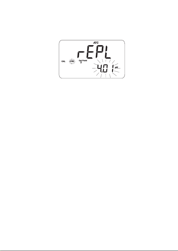
Use the arrow keys to select the buffer to be
replaced, then press CFM to confirm or CAL to
exit calibration without replacing.
CLEAR CALIBRATION
If the SHIFT and CLR keys are pressed at any time
during calibration, the “CLEAR CAL” tag lights up and
the “donE” message is displayed on the secondary LCD.
All previous calibrations are cleared and the instrument
continues the procedure. The points already confirmed
for the current calibration are not deleted.
The “CAL DUE” message will blinks in measurement
mode to advise the user that a pH calibration is required.
Note: If SHIFT and CLEAR are pressed during the
first calibration point, the instrument returns to
measurement mode.
24
Page 25

RELATIVE mV CALIBRATION
• To enter relative mV calibration mode, press CAL from
relative mV measurement mode. The relative mV is
displayed on the primary LCD and the absolute mV
value on the secondary LCD.
• Use the arrow keys to change the displayed relative
mV value.
• When the reading is stable and the relative mV offset
is inside the offset window (±200.0 mV), the CFM
tag will be displayed.
• Press CFM to confirm relative mV calibration and the
instrument will return to normal measurement mode.
• If the absolute mV reading is out of range or the relative
mV offset is out of the offset window, the WRONG
tag will blink.
Change the input value or the relative
mV offset to complete the calibration procedure.
25
Page 26
GOOD LABORATORY PRACTICE (GLP)
GLP is a set of functions that allows data storage (and
retrieval) about the electrode status and maintenance.
All data regarding pH and relative mV calibrations are
stored in the instrument memory.
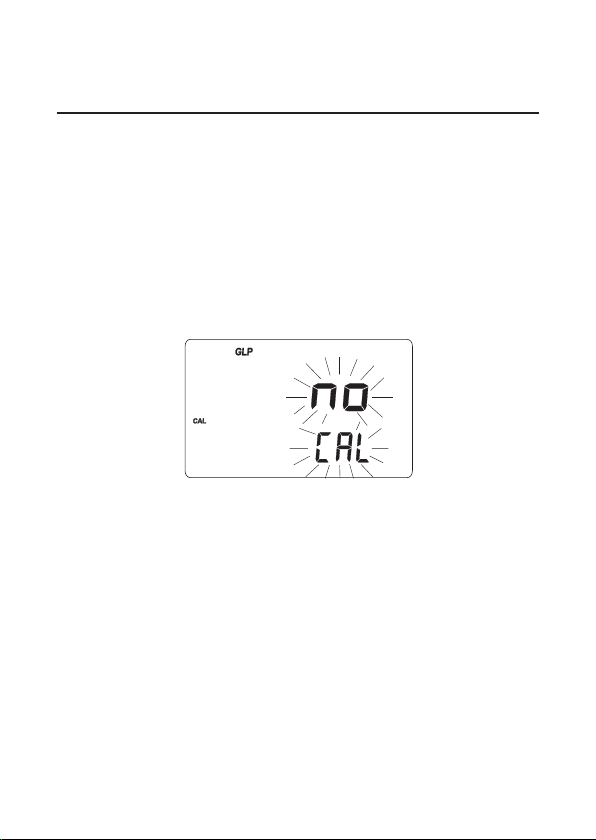
To enter GLP mode, press SHIFT and then GLP key.
If no calibration has been performed, the “no CAL”
message will blink.
CALIBRATION TIME-OUT ALARM
The instrument allows to set the number of days (from
1 to 7) before the next required pH calibration. The
default setting is “OFF” (disabled).
At start-up the instrument checks if the calibration time-out
has expired. If yes, the “CAL DUE” message blinks to
advise the user that a new calibration is required.
26
Page 27
Note: If the instrument was not calibrated or all
calibration data were cleared, the “CAL DUE”
message is displayed even if the feature is
disabled in the setup menu.
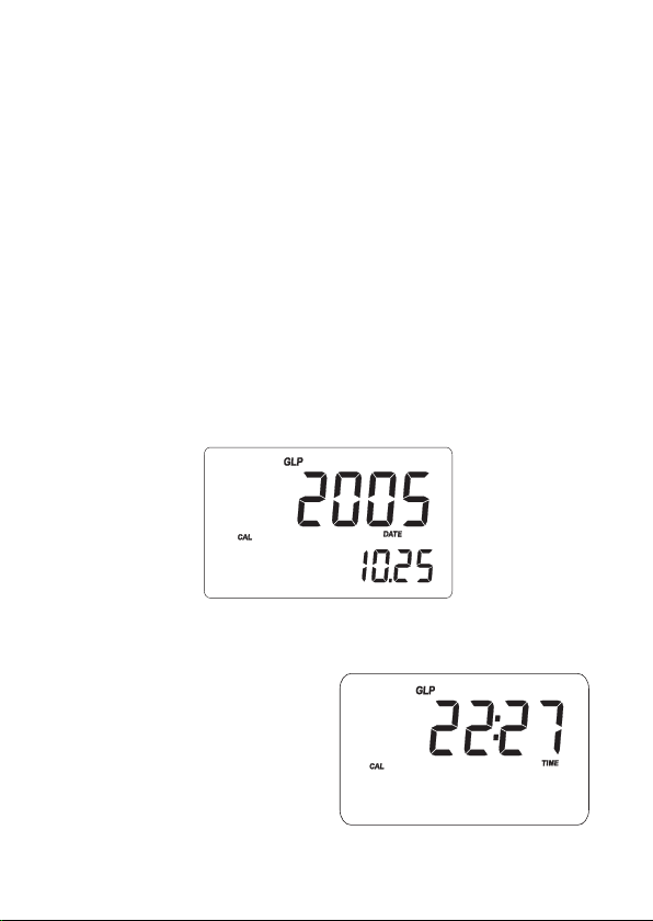
LAST pH CALIBRATION DATA
The last pH calibration data are stored automatically after
a successful calibration.
To view the pH calibration data, from pH measurement
mode press SHIFT and then GLP key. The instrument
will display the date (yyyy.mm.dd) of last calibration.
Use the up arrow key to view all calibration parameters
in the following sequence:
• The time (hh:mm) of the
last calibration.
27
Page 28
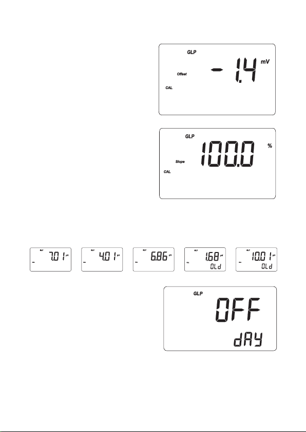
• The pH calibration offset.
• pH calibration slope (the
GLP slope is the average
of the calibration slopes;
the percentage is referred
to the ideal value of 59.16
mV/pH).
• Calibration buffers in the order used for calibration,
together with the corresponding warnings.
• Calibration time-out alarm
status. The display shows
“OFF” if the feature is
disabled, or the days
remaining before the
calibration alarm will be
activated, or after the
calibration is expired (e.g. -3).
28
Page 29
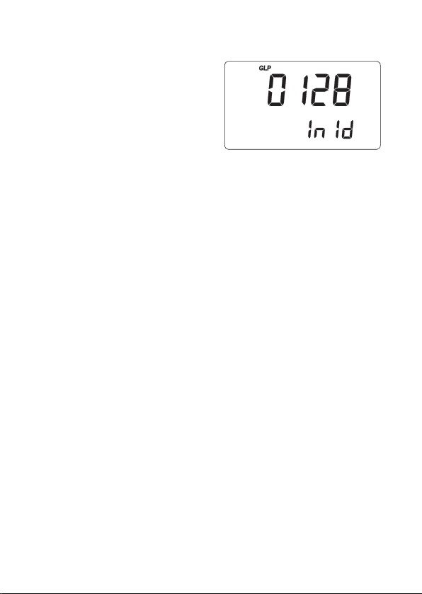
• The instrument ID.
Notes:
• The “OLd” message displayed beside a buffer
value means that this buffer was not used during
last calibration. Press SHIFT and then SETUP
key to see the old calibration date (or time, if old
calibration date is the same as the last procedure).
• The “no buF” message means that calibration
was performed at less than five points.
29
Page 30

LAST RELATIVE mV CALIBRATION DATA
Last relative mV calibration data are stored automatically
after a successful calibration.
To view the relative mV calibration data, from normal
relative mV measurement mode press SHIFT and then
GLP key. The instrument will display the date
(yyyy.mm.dd) of the last calibration.
Use the up arrow key to view all logged calibration
parameters in the following sequence:
• Last calibration date and time
• Relative mV calibration offset
• Instrument ID as in pH GLP mode
Press SHIFT and then GLP key at any moment to
return to normal measurement mode.
30
Page 31
SETUP
Setup mode allows viewing and modifying the following
parameters:
• Calibration alarm time-out
• One-point calibration behavior
• Temperature measure unit
• Current date (yyyy.mm.dd)
• Current time (hh:mm)
• Printer status
• Auto-off
• Baud rate
• Command prefix (serial communication, AD132 only)
• Instrument ID
• To enter SETUP mode, from measurement mode press
SHIFT and then SETUP.
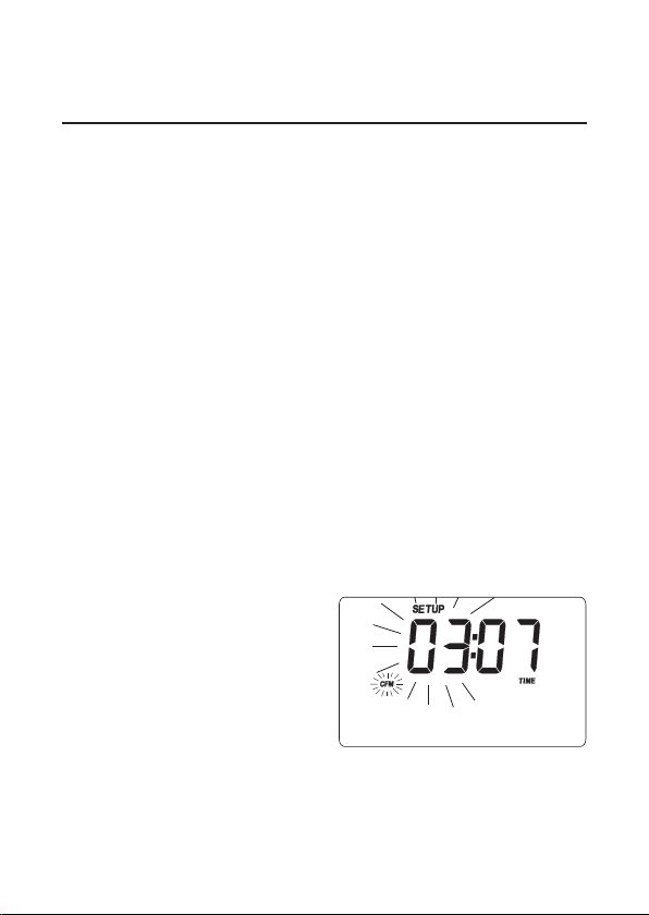
• Press CAL to change the
item value. The selected
item (e.g. hour, while
setting the time) and
“CFM” tag will blink.
• Use the arrow keys to
scroll the available values.
(AD132 only)
(serial communication, AD132 only)
31
Page 32
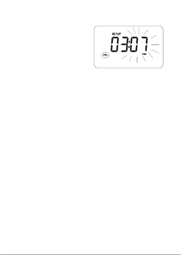
• If another item has to be
set (e.g. minutes), press
RANGE or left/right
arrow key, and the item
will start blinking.
• Use the arrow keys to scroll the available values.
• Press CFM to confirm or CAL to escape.
• Use the arrow keys to select the next/previous
parameter.
32
Page 33
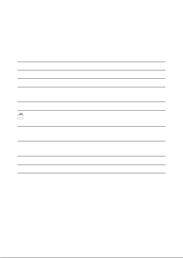
The following table lists all the available SETUP parameters,
their valid values and the factory settings (default):
Item Description Valid values Default
CAL DUE Time-out alarm OFF, 1 to 7 days OFF
1 Pnt 1-point cal. behavior Pnt, OFFS Pnt
tEMP Temperature unit °C, °F °C
Date Date (yyyy.mm.dd) 2000.01.01 2004.01.01
to 2099.12.31
Time Time (hh:mm) 00:00 to 23:59 00:00
Printer status ON, OFF OFF
(AD132 only)
bAUd Baud rate 600, 1200, 2400 2400
(AD132 only) 4800, 9600
PrEF Command prefix 0 to 47 16
(AD132 only)
AOFF Auto-off no or 5 minutes no
In Id Instrument ID 0000 to 9999 0000
33
Page 34
LOG-ON-DEMAND
This feature allows the user to log pH and Rel mV
measurements, together with temperature.
Moreover, for AD132 all logged data can be transferred
to a PC or printed through the RS232 port.
Both models AD131 and AD132 can store up to 500
samples into memory.
LOGGING
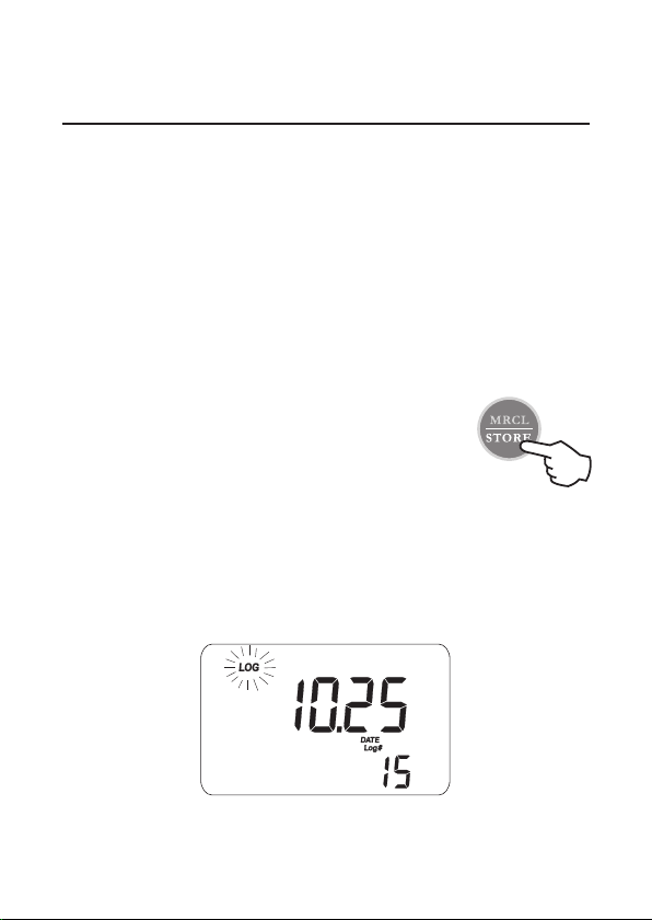
To store the current reading into memory,
press the STORE key from measurement
mode.
The instrument displays the current date (mm.dd) on the
primary LCD, while the secondary LCD shows the
record number with the “LOG” tag blinking for a few
seconds and then the number of free locations.
34
Page 35
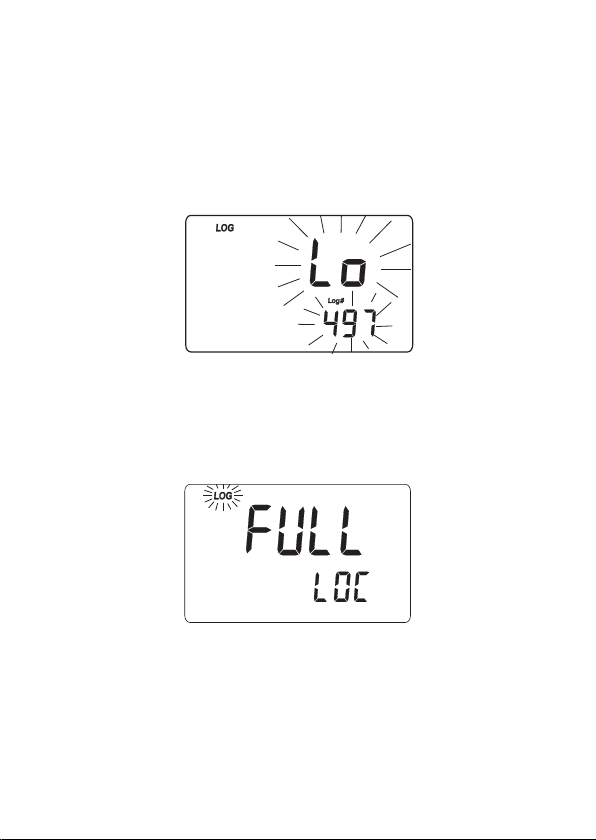
If there are less than 6 memory locations left, the record
number and the “Lo” message will blink for a few
seconds to alert the user, and then the number of free
locations is displayed.
If the logging space is full, the “FULL LOC” message
will be displayed for a few seconds together with the
“LOG” tag blinking, followed by the “FrEE 0” message.
The instrument returns to normal measurement mode.
35
Page 36
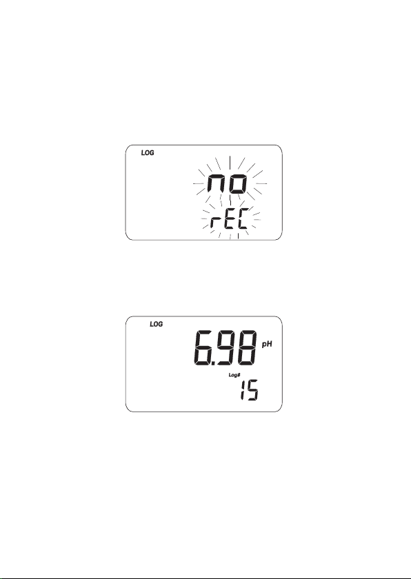
VIEWING LOGGED DATA
To retrieve the information stored, press SHIFT and then
MRCL from measurement mode. If no data were logged,
the “no rEC” message blinks on the LCD.
Otherwise, the instrument displays the memorized pH
or relative mV reading, and the lot number.
Pressing SHIFT and then SETUP key while in memory
recall mode, the secondary LCD will toggle between
the lot and the record number. Use the arrow keys to
select a different lot or record.
36
Page 37

Press RANGE key to scroll all logged parameters,
displayed as shown in the table below:
Parameter Primary LCD Secondary LCD
mV mV reading Temperature
TIME Hour & minutes Seconds
DATE Year Month & day
OFFSET Offset value Lot or record number
SLOPE Slope value Lot number
Notes:
• To view the previous logged parameter, press
the left arrow key.
• In relative mV memory recall mode, the offset
value is not available and the display shows
dashes “----”.
• The record number is an identification number
inside a lot.
After scrolling all logged parameters, the meter displays
the “dEL” message together with the lot number.
Note: Pressing SHIFT and then SETUP key, the
instrument toggles between record number and
“del ALL”.
37
Page 38
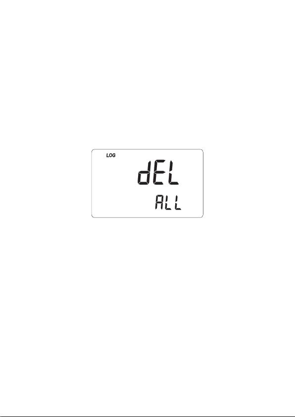
• Press SHIFT and then CLEAR to delete the selected
record or all records.
Note: Positions remain free in the log-on-demand lot
by deleting the last logged sample or all lot.
• If the “dEL All” option was selected, all logged data
are deleted and the instrument returns to normal
measurement mode.
• Press SHIFT and MRCL at any time to return to
measurement mode.
38
Page 39

HOLD FUNCTION
To freeze a stable reading on the LCD, press HOLD
key from normal measurement mode.
The “Auto” and “H” tags will blink on the LCD until the
reading stabilizes.
When the reading is stable, the “Auto” and “H” tags
stop blinking and the reading is frozen.
Press HOLD key again to return the normal measurement
mode.
Note: Pressing RANGE the instrument will skip to the
displayed range, without leaving the HOLD
mode. The STORE key also holds HOLD mode.
Pressing SHIFT and then SETUP, GLP or MRCL
key, the instrument leaves the HOLD mode and
performs the selected function.
39
Page 40

PRINTING (AD132 only)
When connected to an external serial printer, a complete
set of information can be printed.
Printer specifications:
• at least 16 characters / line
• baud rate 9600
• 9-pin RS232 input
Data can be printed on demand (from measurement, GLP
and SETUP modes) by pressing SHIFT and then PRINT.
Note: To cancel printing, press SHIFT and then PRINT
again.
While in pH measurement mode,
the printout provides the following
information:
Date 2004/01/01
Time 02:25:17
pH 7.01
mV -23.2
°C 26.3
When in GLP mode, the printout provide the following
information:
40
Page 41
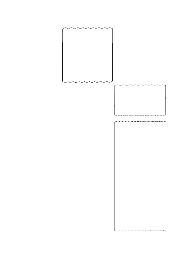
• For pH range:
GLP pH
Instr ID 0003
Date 2004/01/01
Time 01:04:32
Cal Time Out OFF
Offset -22.9mV
Slope 100.0%
Cal Buffers:
pH 7.01
• For relative mV range:
GLP Rel mV
Instr ID 0003
Date 2004/01/01
Time 02:27:35
Off.RelmV -23.3
• Setup mode: if SHIFT and
PRINT are the first keys pressed
after entering the setup mode, a
setup table of contents will be
printed:
41
INSTRUMENT SETUP
Calibration
Alarm Time Out
One point cal
behavior
Temperature unit
Current Date
Current Time
Printer ON/OFF
AutoOff 5/NO
Baud rate
Command prefix
Instrument ID
CAL-enter in
modifying mode
SET-exit SETUP
RANGE-select
parameter
See also items
Help printings
Page 42
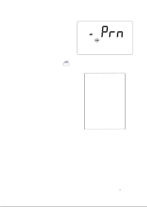
• When exiting the setup
mode, the instrument
asks if the setup report
has to be printed. The
“Prn” message will be
displayed, together with
the printer symbol ( )
and the CFM tag blinking.
• Press CFM to print the
setup report or CAL to
exit without printing.
SETUP REPORT
Instr ID 0003
Cal Time Out OFF
One Cal Point
pn t
Date 2004/01/01
Time 02:28:34
Printer O N
Auto-off no
Baud Rate 2400
Comm prefix 16
Temperature °C
42
Page 43
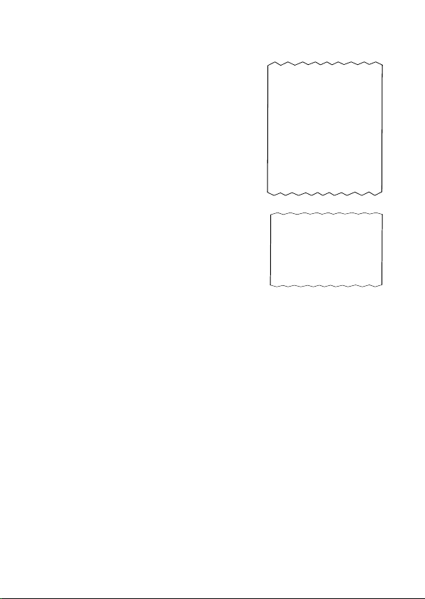
From setup mode, if CAL and then
PRINT is pressed for a chosen
parameter, a help printout will provide
the following information (e.g. Alarm
Time-Out):
SET
ALARM TIME OUT
(OFF or 1-7)
Active Keys:
ˆ -increment
v -decrement
CAL-exit, no save
CFM-save & exit
CLR-set to default
When in logging mode, an automatic
printout will provide the following
information for pH and mV:
43
Date 2004/01/01
Time 01:13:53
pH 7.01
mV -23.3
°C 26.2
Page 44
BATTERY REPLACEMENT
When the battery level becomes too low to ensure reliable
readings, the meter automatically turns off.
Battery replacement must only take place in a safe area
and using the battery type specified in this instruction
manual.
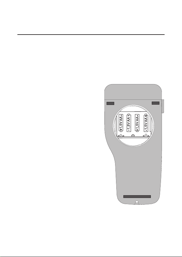
To replace rundown batteries,
remove the battery cover and
substitute all four 1.5V AA
alkaline batteries with new
ones, while paying attention
to the correct polarity.
Reattach and tighten the
battery cover making sure
that the gasket is in place.
Note: When batteries are
removed, the meter
can remember date &
time for about 1 minute.
After that, it will be
necessary to set again
date & time through
the setup procedure.
44
Page 45

TEMPERATURE CALIBRATION
(for technical personnel only)
The instruments are factory calibrated for temperature.
Adwa’s temperature probes are interchangeable and no
temperature calibration is needed when they are replaced.
If temperature measurements are not accurate, temperature
new calibration should be performed.
For an accurate recalibration, contact your dealer or the
nearest Adwa Customer Service Center, or follow the
instructions below.
• Prepare a vessel containing ice and water, and
another one containing hot water at approximately
50°C (122°F). Place insulation material around the
vessels to minimize temperature drift.
• Use a calibrated thermometer with a resolution of 0.1 °C
(or 0.1 °F) as reference thermometer. Connect the
supplied
socket on the rear panel.
• With the instrument off, press and hold the CAL & up
arrow keys, then power on the instrument. The “CAL”
tag lights up and the secondary LCD shows 0.0 °C (or
32.0 °F). The primary LCD will display the measured
temperature or “----”, if the reading is out of range.
AD7662 temperature probe to the appropriate
45
Page 46
• Immerse the temperature probe into the vessel with
ice and water as close as possible to the reference
thermometer. Allow a few seconds for probe thermal
stabilization.
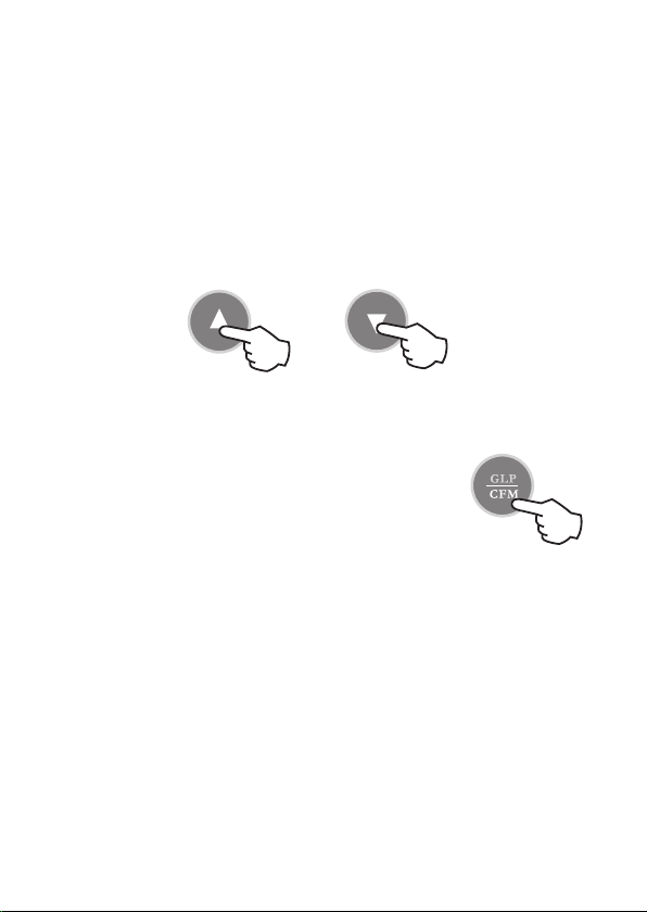
• Use the arrow keys to set the reading on the secondary
LCD to that measured by the reference thermometer.
• When the reading is stable and close to the selected
calibration point, the CFM tag starts blinking.
• Press CFM to confirm. The secondary
LCD will display 50.0°C (or 122.0°F).
• Immerse the temperature probe into the second vessel
as close as possible to the reference thermometer.
Allow a few seconds for probe thermal stabilization.
• Use the arrow keys to set the reading on the secondary
LCD to that of the hot water measured by the reference
thermometer.
• When the reading is stable and close to the selected
calibration point, the CFM tag starts blinking.
46
Page 47

• Press CFM to confirm. The instrument
returns to normal measurement mode.
Notes:
• If the reading is not close to the selected
calibration point, the WRONG tag will blink.
Change the temperature probe and restart
calibration.
• Press CAL at any time to quit the procedure.
mV CALIBRATION (for technical personnel only)
The instruments are factory calibrated for mV range.
Adwa’s ORP electrodes are interchangeable and no mV
calibration is needed when they are replaced.
If measurements are not accurate, a mV recalibration
should be performed.
For an accurate recalibration, contact your dealer or the
nearest Adwa Customer Service Center, or follow the
instructions below.
A two or three-point procedure can be performed at 0.0,
600.0 and 1800 mV.
47
Page 48

• Attach a mV simulator with an accuracy of ±0.1 mV
to the BNC connector on the rear panel.
• With the instrument off, press and hold the CFM &
STORE keys, then power on the instrument. The CAL
tag lights up and the secondary LCD shows 0.0 mV.
• Set the simulator to 0.0 mV. When the reading is stable
and close to the selected calibration point, the CFM
tag starts blinking.
• Press CFM to confirm and the secondary LCD will
display the second expected value (600.0 mV).
• Set the simulator to 600.0 mV. When the reading is
stable and close to the selected calibration point, the
CFM tag starts blinking.
• Press CFM to confirm. The secondary LCD will
display the third expected value (1800 mV).
• Set the simulator to 1800.0 mV. When the reading is
stable and close to the selected calibration point, the
CFM tag starts blinking.
• Press CFM to confirm. The instrument returns to
measurement mode.
Notes:
• If the reading is not close to the selected point,
the WRONG tag will blink. Verify the calibration
48
Page 49

conditions or contact your dealer if calibration
can not be performed.
• To return to normal measurement mode, press
CAL at any moment during calibration.
• If the calibration procedure is ended after the
600.0 mV point is confirmed, the meter returns
to normal measurement mode and stores a 2point calibration data.
PC INTERFACE (AD132 only)
Data can be transferred from the instrument to the PC
using the ADSW10 Windows® compatible software
(optional).
ADSW10 also offers graphing and on-line help feature.
Data can be exported to the most popular spreadsheet
programs for further analysis.
To connect your instrument to a PC, use the AD9551
optional Adwa cable. Make sure that the instrument is
switched off and plug the cable to the instrument RS232
socket and to a serial port of your PC.
If not using the AD9551 cable, communication between
instrument and PC may be not possible, due to different
RS232 connector configuration.
49
Page 50

pH ELECTRODE CONDITIONING &
MAINTENANCE
PREPARATION PROCEDURE
Remove the pH electrode protective cap. DO NOT BE
ALARMED IF SALT DEPOSITS ARE PRESENT.
This is normal with electrodes and they will disappear
when rinsed with water.
During transport, tiny bubbles of air may form inside the
glass bulb affecting proper functioning of the electrode.
These bubbles can be removed by “shaking down” the
electrode as you would do with a glass thermometer.
If the bulb and/or junction are dry, soak the electrode in
AD70300 storage solution for at least one hour.
STORAGE PROCEDURE
To minimize clogging and assure a quick response time,
the glass bulb and the junction of the pH electrode should
be kept moist and not allowed to dry out.
Replace the solution in the protective cap with a few
drops of AD70300 storage solution .
NEVER STORE THE ELECTRODE IN DISTILLED
OR DEIONIZED WATER.
50
Page 51

PERIODIC MAINTENANCE
Inspect electrode and cable. The cable used for
connection to the instrument must be intact and there
must be no points of broken insulation on the cable or
cracks on the electrode stem or bulb. Connectors must
be perfectly clean and dry. If any scratches or cracks
are present, replace the electrode. Rinse off any salt
deposits with water.
CLEANING PROCEDURE
Soak in AD7061 general cleaning solution for approximately
30 minutes.
IMPORTANT: After performing any of the cleaning
procedures, rinse the electrode thoroughly with AD7000,
refill the reference chamber with fresh electrolyte and
soak the electrode in AD70300 storage solution for at
least 1 hour before taking measurements.
51
Page 52

TROUBLESHOOTING GUIDE
SYMPTOMS
Slow response/
excessive drift.
Readings
fluctuate up and
down (noise).
Only blinking
dashes during
pH measurements.
Blinking reading
during measurements.
Out of range in
the mV scale.
PROBLEM
Dirty pH electrode.
Clogged/dirty
junction. Low
electrolyte level
(for refillable
electrodes only).
Out of range in the
pH scale.
Reading out of
range or electrode
not connected.
Dry membrane/
junction.
SOLUTION
Soak in AD7000
solution for 30
minutes and then
clean the electrode.
Clean the electrode.
Refill with fresh
solution (for
refillable electrodes
only).
Make sure the pH
sample is in the
specified range.
Calibrate. Check
electrolyte level
and general state
of the electrode.
Check sample or
connect electrode.
Soak in AD70300
storage solution
for 1 h.
52
Page 53

SYMPTOMS
The meter does
not work with
temperature
probe.
The meter fails to
calibrate or gives
faulty readings.
Explicit warnings
are displayed
during pH
calibration.
At start-up the
meter displays all
LCD permanently.
“Prn Eror” error
message displayed.
“Err xx” error
message displayed.
PROBLEM
Out of order
temperature probe.
Broken or out of
order pH electrode.
Dirty/broken pH
electrode, contaminated reference or
buffers.
One of the keys is
blocked.
Printer error.
Internal error.
SOLUTION
Replace the probe.
Replace the
electrode.
Follow displayed
instructions.
Check the
keyboard or
contact the
vendor.
Turn the meter off
and then turn it
on. If the error
persist, contact
your dealer.
Turn the meter off
and then turn it
on. If the error
persist, contact
your dealer.
53
Page 54

ELECTRODES, PROBES AND SOLUTIONS
AD1230B pH electrode with Epoxy body, tip protection
bottle, BNC connector with protection
sleeve and 1 m cable
AD3230B ORP electrode with Epoxy body, tip
protection bottle, BNC connector with
protection sleeve and 1 m cable
AD7662 Stainless steel temperature probe with 1 m
cable.
AD70004P pH 4.01 buffer solution, 20 ml sachet, 25 pcs.
AD7004 pH 4.01 buffer solution, 230 ml bottle
AD70007P pH 7.01 buffer solution, 20 ml sachet, 25 pcs.
AD7007 pH 7.01 buffer solution, 230 ml bottle
AD70010P pH 10.01 buffer solution, 20 ml sachet, 25 pcs.
AD7010 pH 10.01 buffer solution, 230 ml bottle
AD7061 Electrode cleaning solution, 230 ml bottle
AD70300 Electrode storage solution, 230 ml bottle
AD70000P Electrode rinsing solution, 20 ml sachet,
25 pcs.
AD7000 Electrode rinsing solution, 230 ml bottle
AD9551 Serial communication cable, 5 to 9 pins
54
Page 55

55
Page 56

ADWA HUNGARY Kft.
Alsókikötõ sor 11, 6726 Szeged, Hungary
Tel. +36 62 317 878
Fax +36 62 550 610
www.adwainstruments.com
MANAD132 09/14
 Loading...