

Page 1

Owner’s
mcmuai
Advent
Model
300
FM
Stereo
Receiver
Page 2
Contents
W/o
shoc
nt
eXP
baard
.thiss
do
1
Introduction
1
Placement
2
Loudspeaker
Phasing
4
Source
Turntable connection
Tape
Auxiliary
Convenience
Antenna
6
Operating
8
Notesonoperating
Volume
Bass
Output
Tape
Circuit
11
FM
Muting
Multipath
Antenna
Antenna
13
Using
with
Connecting
+18
Using
Connecting
connections
deck
connections
treble
and
protection
recording
breaker
reception
distortion
orientation
improvement
additional
the
Model
VDC
a
separate
connection
Controls
connections
outlet
the
fuses
and
playback
and antennas
equipment
300
an
additional
power
equipment
other
Model
300
pairofloudspeakers
amplifier
15
Troubleshooting
22
Warranty
22Incaseofdiificulty
23
Owner’s
record
guide
Page 3
Introduction
Placement
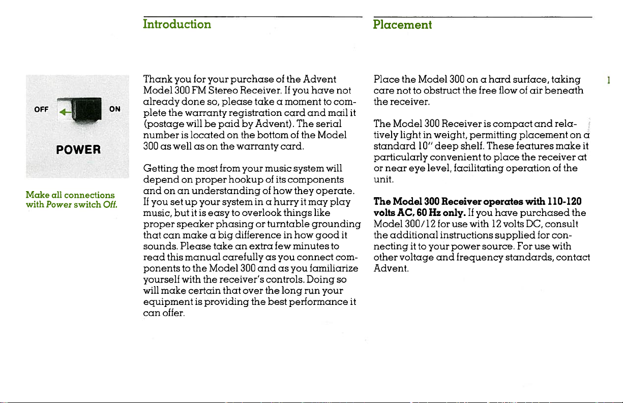
OFF
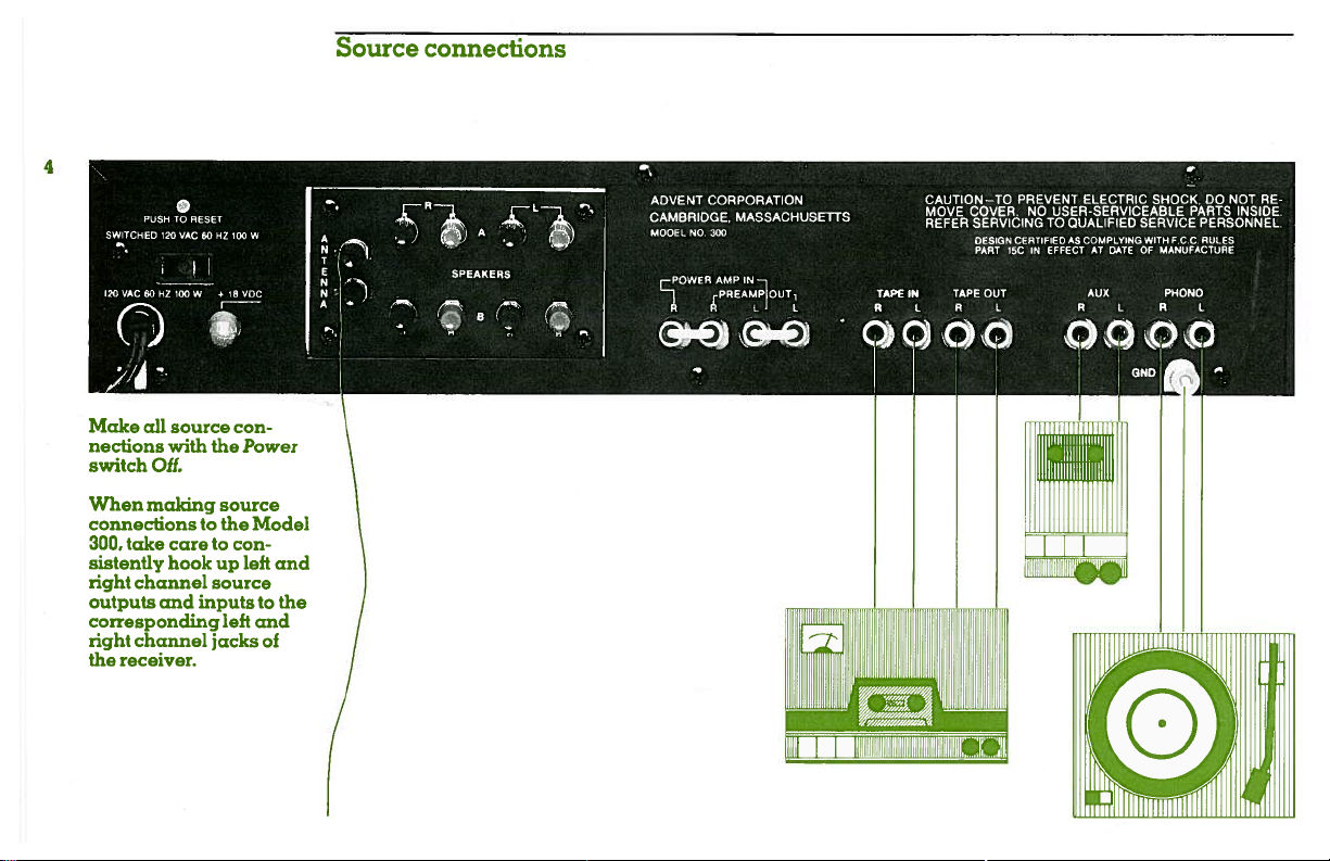
Make
with
POWER
all
connections
Power
switch
ON
OfL
Thank
Model
already
plete
numberislocatedonthe
300aswellason
Getting
depend
andonan
If
music,
proper
that
sounds.
read
ponentstothe
yourself
will
the
(postage
you
setupyour
can
this
make
you
for
your
purchaseofthe
300 FM
done
so,
warranty
Stereo
please
Receiver.Ifyou
takeamomenttocom
registration
willbepaidbyAdvent).
bottomofthe
the
warranty
most
from
the
on
proper
your
hookupofits
understanding
systemina
butitis
easytooverlook
speaker phasing
makeabig
Please
manual
with
the
differenceinhow
takeanextra
carefully
Model
300
receiver’s
certain that
or
andasyou familiarize
over
music
of
how
hurryitmay
turntable
few
as
controls.
the
equipmentisproviding the best
can
offer.
Advent
have
card
and
The
card.
system
components
they
things
minutes
connect
you
Doing
long
run
performance
not
mail
serial
Model
will
operate.
play
like
grounding
good
it
to
com
so
your
it
it
Place
the
care
not
to
the
receiver.
The
Model
tively
lightinweight,
standard
particularly
or
near
eye
unit.
The
Model
volts
AC,
Model
the
necting
other
300/12
additional
ittoyour
voltage
Advent.
Model
300ona
obstruct the
300
Receiveriscompact
free
permitting
10”
deep
shelf.
convenienttoplace
level,
facilitating
Receiver
300
60Hz
only.Ifyou
for
use
with12volts
instructions
power
and
frequency
hard
surface,
flowofair
placement
These
features
operationofthe
operates
have
purchased
supplied
source.
For
standards,
the
with
DC,
taking
beneath
rela
and
make
receiver
110-120
consult
for
con
use
with
contact
on
the
a
it
at
Page 4
___
___
___
Make
2
nections
switch
When connecting
speaker
speaker
certain
splayed
can
short
terminals
speaker
receiver’s
Do
not
(red)
directly
Should
conditions
operating
damage
requiring
covered
warranty.
speaker
all
with
Off.
wires
terminals,
that
wire
two
together,
terminal
chassis.
connect
speaker
together.
any
the
may
service
under
the
to
no
wires
filaments
speaker
the
terminals
of
the
occur
Model
result
the
con
Power
the
make
or
to
the
“hot”
above
while
not
or
a
300,
Loudspeaker
4
A
N
T
E
N
‘
N
A
connections
R
—
L
..
PEAKE
S
.
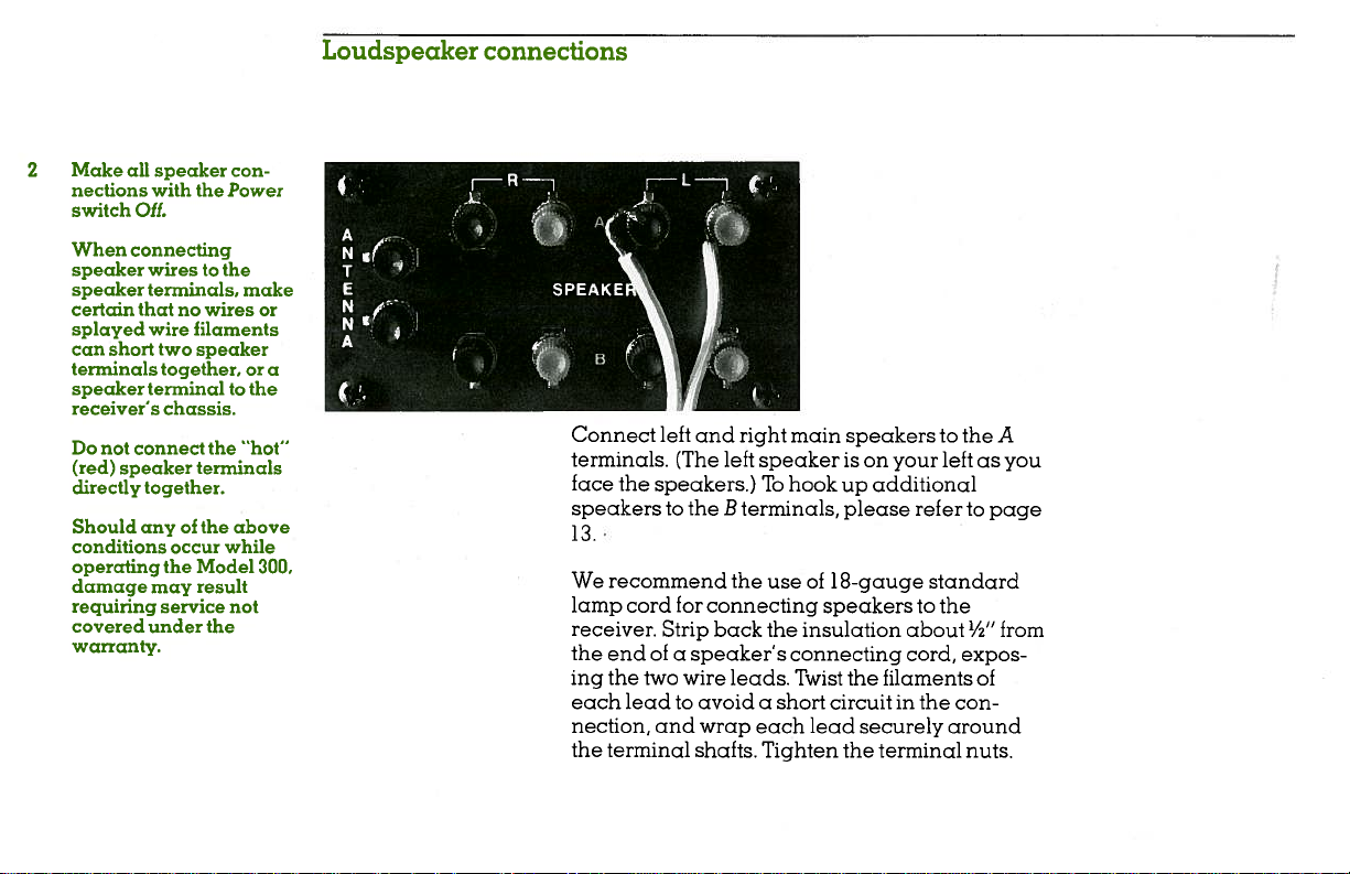
Connect
terminals.
face
the
speakers
i
.
recommend
We
lamp
cord
receiver.
the
end
ing
the
each
lead
nection,
the
terminal
L
left
and
(The
speakers.)
to
the
for
Strip
speaker’s
of
a
wire
two
avoid
to
wrap
and
shafts.
right
left
speaker
To
B
terminals,
the
use
connecting
back
the
leads.
a
short
each
Tighten
main
speakers
is
on
hook
up
please
18-gauge
of
speakers
insulation
connecting
Twist
the
circuit
lead
securely
the
to
your
additional
refer
standard
to
the
about
cord,
filaments
in
the
terminal
the
left
as
to
½”
expos
of
con
around
nuts.
A
you
page
from
Page 5
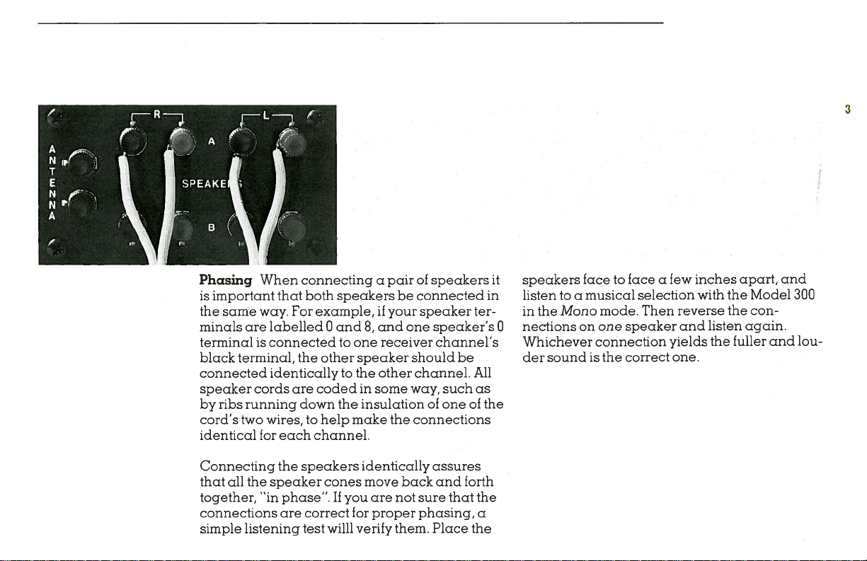
Phasing
is
important
the
same
minals
terminalisconnectedtoone
black
connected
speaker
by
cord’s
identical
are labelled0and
terminal, the
cords
ribs
running
two
connectingapairofspeakers
When
that
both
speakers
way. For
identically
wires,tohelp
for
example,ifyour
other
are
codedinsome
down
each
channel.
speaker
to
the
insulationofoneofthe
the
make
and
8,
receiver
other
connected
be
speaker
one
should be
channel.
way,
the
connections
ter
speaker’s
channel’s
All
such
as
it
in
0
speakers
listentoa
Mono
in
the
nections
Whichever
soundisthe
der
facetofaceafew
mode.
one
selection
Then
speaker
correct
yields
one.
musical
on
connection
inches
with
reverse
and
the
the
listen
the
apart,
Model
con
again.
fuller
and
and
300
lou
Connecting
that
all
the
together,
connections
simple
listening
the
speakers
speaker
“in
phase”.Ifyou
are
correct
test
cones
willl
identically
move
back
are
not
for
proper
verify them.
assures
and
sure
that
phasing,
Place
forth
the
a
the
Page 6
Source
connections
0
PUSH
TO
)
/
all
Oil.
making
RESET
20
SAC
source
with
AS
HZ
the
•1RVOC
source
SWITCHED
S.
I2OVACNOHZIQOW
I
•
Make
nections
switch
When
connectionstothe
300,
take
care
sistently
right
channel
outputs
corresponding
channel
right
receiver.
the
hookup
and
inputs
to
source
left
jacks
00
W
con
Power
Model
con
left
and
CORPORATION
ADVENT
A
N•’
SPEAKERS
CAMBRIDGE,
MODEL
r
cc
NO
POWER
MASSACHUSETrS
300
IN
AMP
çPREAMOUTi
)
CAUTION—TO
MOVE
REFER
TAPE
TAPE
IN
“a:
PREVENT
COVER
SERVICINGTOQUALIFIED
DESIGN CERTIFIED
15CINEFFECT
PART
OUT
ELECTRIC
NO
USER-SERVICEABLE
COMPLYING
AS
AT
DATE
AUX
SHOCK.
SERVICE
WItH
OF
MANUFACTURE
GNO,
PARTS
P.CCRULES
PHONO
DO NOT
INSIDE.
PERSONNEL
—
RE
and
the
to
of
rr’i_
Page 7
Turntable
connecting
your
screw
used
an
Be
and
well
turntable
chassis,
its
deck
the
of
the
the
or
additional
tridge.
seated
tioned
prevent
If
from
nal
panel.
Tape
nect
jacks
nect
input
Auxiliary
be
as
connection
turntable
a
that
sure
the
that
from
away
hum pickup.
has
connect
the
below
connection
output
Tape
record
for
jacks
Model
jacks
out
jacks
connections
additional
tape
The
with
the
phono
connecting
any
a
ground
it
Phono
For
of
the
For
300.
the
of
of
the
The
high
deck.
Phono
a
AC
the
to
jacks
tape
deck
tape
receiver
tape
Aux
level
jacks
magnetic
are
plugs
cables
power
running
wire
Ground
on
the
playback,
the
to
recording,
deck.
input
sources,
are
car
firmly
are
cords
rear
Tape
to
the
jacks
for
posi
to
termi
con
con
such
in
may
Convenience
is
outlet
AC
other
components
sumption.
switch
Power
Antenna
short-wire
the
separated
wires.
before
will
the
to
page
Power
Model
120
source
The
receiver,
Otherwise,
they
degraded.
be
section
11.
cord
300
volts,
60Hz;
you
if
outlet
provided
outlet
This
of
Model
whip
be
from
reach
on
Connect
a
convenient
to
have
A
up
of
operates
receiver
the
300
antenna.
that
sure
the
power
FM
the
For
reception
FM
your
orto
purchased
switched
the
on
to
100
equipped
is
When
the
cord
signals
antenna,
further
power
the
source
12
volt,
120
panel
rear
power
watts
when
only
On.
is
position
you
antenna
the
and
absorbed
be
can
reception
and
information,
antennas
and
cord
AC
of
DC
the
power
Model
volt
to
with
is
speaker
the
of
power,
Hz
60
power
con
the
a
refer
300
on
12.
When
portable
a
as
Aux-L
300’s
sound
system.
connecting
cassette
jack
Aux-R
or
Stereo/Mono
through
play
will
monophonic
a
player,
listen
and
switch
set
both
source,
either
use
the
with
Mono
to
speakers
the
Model
that
so
of
such
the
your
Page 8
Operating
U
AUG
,G_000
TAPE
MONITOR
TUNED
PUONO
LOUDNESS
VOLUME
00
MONO
BALANCE
controls
STEREO
BASS
On
MUTING
TREBLE
100
102
98
O
ON
SPEAKERS
PHONES
“‘
Ofl
96
\\
94
92\
90
88
104
/
106
I
/
108
ADVE\T
MODEL
POWER
+
300
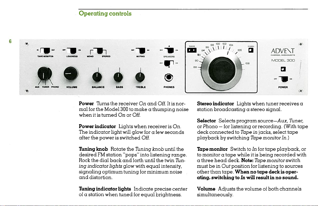
Power
mal
whenitis
Power
The
Turns
for
the
turned
indicator
indicator
the
Model
light
receiver
to
300
On or
Lights
will
Off.
glow
after the powerisswitched
Tuning
desired
Rock
ing
signaling
and
Tuning
ofastation
knob
FM
the
dial
indicator
optimum
distortion.
indicator
Rotate
station
back
lights
when
“pops”
and
glow
tuning
lights
tuned
the
forth
On
and
Off.Itis
make
a
thumping
when
receiverisOn.
forafew
seconds
Off.
Tuning
with
into
until
equal
for
minimum
knob
listening
the
twin
intensity,
until
Indicate precise
for
equal
brightness.
nor
noise
range.
Tun
noise
center
the
Stereo
indicator
station
Selector
or
deck
playback
Tape
to
a
broadcastingastereo
Selects
Phono
—
connectedtoTapeinjacks,
by
monitor
monitoratape
three
head
mustbein
other
than
ating,
switching
Volume Adjusts
Lights
program
for
listeningorrecording.
switching
SwitchtoIn
whileitis
deck.
Note:
Out position
tape. Whennotape
toInwill
the
simultaneously.
when
tuner
signal.
source—Aux,
Tape
monitor
for
tape
being recorded
Tape
monitor
for
listeningtosources
deckisoper
resultinno
of
volume
both
receives
(With
select
In.)
playback,
sound.
channels
a
Tuner,
tape
tape
or
with
switch
Page 9
Balance
right
tion
right
the
Loudness
treble
Adjusts
channels
to
the
leftofthe
channel
central
position
In
to
provideamore
when listening
ear’s
at
up,
source
300.
records
FM
stations
relative
loudness
the
for
and
highs
turned
decreases.
cally
Mono/Stereo
mal
operation.
mono
to
a
Model
the
older
stereo
Mono.
in
relative
the
proper
for
central
output;
rotation
reduces
at
On
low
position,
volume.
the
insensitivitytoextreme
low
volume
compensation
Leave
Use
in
Mono
Stereo
connectedtoone
Noise
Note:
(mono
or
stereo)
can
be
volume
stereo
position
to
left
boosts
pleasing
It
levels.
mode
and
reduced
of
left
balance.
Rota
reduces
from
right
the
bass
output.
and
balance
channel
tonal
compensates
Volume
As
automati
position
for
when listening
channel
from
listening
by
from
distant
distortion
and
and
lows
is
nor
of
Bass
and
on
treble
Muting
station
Switch
the
Speakers:
Off.
noise
Off
Muting
Speaker pairs
Treble
both
When
Boostorreduce
channels
switched
when tuning
searching
when
circuit
A
and
B
might
Turns
maybeoperated
uallyorsimultaneously
both
Switching
no
sound.
speaker
bass
simultaneously.
eliminates
On,
FM
broadcasts.
to
weak
signals
for
suppress.
speaker
pairs
individ
page
Off
13).
will
(see
pairs
and
inter-
On
Note:
result
or
that
and
in
Phones
with
trostatic
nection
Accepts
a
standard
headphones
to
Refertothe
such
phones.
the
user
stereo
stereo
speaker
instructions
headphones
phone
usually
terminals
that
plug.
require
of
the
accompany
equipped
Note:
con
receiver.
Elec
Page 10

Notes
on
operating
the
Model
300
Volume
setting
linear.
tion
powerofwhich
example,ifthere
no
setting.
The
faucet
while
determines
ume
how
given
output
significantly
phono
higher
at
put,
As
300,
pointofamplifier
at
considerably
The
relationship
and
power
Setting
does
not
mean that
power
output,nomatter
Volume
level
far
the
however,
you
distortion
which amplifier
control
regulates
the
levelofthe
power outputtoachieveagiven
(justaswater
the
faucet
volumeofwater
levelofa
below
preamp,
for
tape
same
subjective
willbethe same.
turnupthe
remains
with
between
outputofthe
the
Volume
you
the
receiver
signal
is
no
adjusts
the
flowofwater
signaltobe
pressure
mustbeopenedtoallow
to
tape
recorderinyour
thatofthe
the
Volume
listening
overloadisreached.
than
volume
Volume
constantly
“clipping”
the
dynamic
Model
controlathalf
are
using
is
capable.
input,
what
gain
through).
pass
Model
setting
for
level.
controlofthe
occurs
range
the
Volume
300isnot
half
For
there
the
Volume
like
(much
from
a
pipe),
amplified
determines
Tithe
system
300’s
will
be
disc
listening
Power
Model
low
until
The
will
vary
of
the
rota
the
will
be
a
vol
a
out
the
point
musical
tingofthe
maximum
system,
harsh,
While
clipping
audible
ation
damage
Bass
vide
treble
The
is
allow
small
rangeoflow
deflection
control
sloping
adjustmentontreble
At
the
can replaceoraugment
Loudness
material,
Bass
undistorted
music
gritty,orfuzzy.
the Model
for
strainorimpairment,
at
severely
your
and
Treble
carefully
balance
Bass
control
correctionofonly
rotationofthe
from
has a
response
low-to-moderate
tone
controlstoboost
switch,
its
bass
content,
control.
will
sustained
loudspeakers.
tailored
relativetothe middle
frequency
the
fixed
When
output
starttosound
300
can
be
periodsoftime
distorted
Bass
has a
center
hinge
provides
compensating
volume
and
Treble
adjustmentofbass
sliding
the
knob,
anditaffectsawider
tones
position.
point,asan
the
tones.
volumes,
bass
the
and
the
you
exceed
into
your
speaker
distorted,
operated
prolonged
inflection
lowest
with
most
large
andortreble
operationofthe
atornear
without
levels
controls
register.
bass
increasing
The
overall
useful
rotations
for
the
point
with
Treble
changes
set
the
i.e.
oper
can
pro
and
to
a
of
Page 11

Response
dB
in
+
10
+5
0
—10
perceived
in
occur
At
louder
controls
effects,
when
that
els.
of
the
room
loudspeakers,
For
be
and
making
that
power
most
Bass
position
as
example,
made
boosting
Bass
demand
control
much
rial.
times
Bass
When
mind
the
where
the
boost
times
tonal
listening
listening
can
the
tonal
or
more
tone
boost
musical
from
requires
power
balance
at
levels,
effectively
balance
deficiencies
voice
broadcasts
intelligible
Treble.
control
logarithmically
on
the
receiver
information
its
normal
the
into
your
ci
musical
lower
volume
smaller
adjust
for
your
of
program
in
can
reducing
by
adjustments,
increases
in
occurs.
to
maximum
receiver
to
loudspeakers
material
lev
rotations
some
mate
some
keep
the
region
Turning
feed
10
in
to
reproduce
Model
ing
300
at
can
300
the
loudest
provide,
response.
Output
tected
protection
fuses
by
operating
the
speaker
impedance
bothofthese
one
or
sound
output
you
the
receiver
the
eliminated
have
Troubleshooting
may
warranty.
20
Frequency
low
frequencies,
to
overload
undistorted
set
fuses
inside
conditions,
terminals,
substantially
will
occur.
require
100
in
cycles
per
and
prematurely.
volume
the
Bass
control
The
Model
the
unit
against
such
asashort
oradrop
below
fuses
blow,atermination
If
this
happens,
other
possible
guide
on
page
service
not
second
will
cause
For
for
300
speaker
in
4
ohms.
causes
16),
covered
the
listen
the
Model
flat
is
pro
abnormal
circuit
Should
and
your
under
of
(see
1000
of
Tone
control
00
curves
20000
Page 12

Contact
mation.
the
have
station
ice
ing
information
certain
Make
connected
protection,
ued
same
the
holders
fuse
behind
the
front
amp,
a
3
4
amp,
recording
Tape
recorded
Model
monitor
Tape
be
may
recording
inputs,
monitor
record,
To
Selector
matically
your
However,
Model
not
before
type
on
the
Bass
of
the
volt
250
250
volt
tape
Tapeinjacks,
300’s
any
in
from
switch
Out.)
select
switch.
fed
dealer
should
300’s
authorized
important.
is
the
that
changing
replace
value.
and
main
the
and
board
fast
blow.
fast
and
a
deck
on
switch
position.
deck
a
Selector
program
a
That
the
from
or
Advent
you
fuses
by
power
fuses
Fuses
circuit
Treble
(nearest
blow;
playback
connected
set
The
to
In.
(For
connected
to
Aux
program
Model
for
find
replaced
Advent,
supply
fuses.
only
are
board,
controls.
the
rear
the
To
the
Selector
listening
and
source
material
300’s
service
necessary
it
by
the
cord
For
with
located
The
front
fuse
play
to
Model
to
the
to
switch
with
Tape
in!
serv
a
follow
is
contin
others
directly
fuse
panel)
is
a
a
the
300’s
switch
a
tape
Aux
Tape
the
is
auto
out
dis
unaf
is
tone
and
and
volume
or
recorder’s
your
to
jacks
Model
fected
to
by
the
inputs,
300’s
controls.
cas
most
the
to
the
through
back
monitor
like
source
Tape
monitor
to
the
may
the
be
In
monitor
switch
elec
Model
volume
a
and
Out.
two
listen
the
passes
the
heads,
with
Tape
and
There
Tape
If
tape
your
decks,
sette
the
before
while
or
In
source
the
of
material
switch
In,
of
in
tronics
300
difference
at
has
deck
you
may
recording
With
Out.
signal
deck
tape
itisrecorded.
between
is
the
is
Tape
simulta
being
If
you
monitor
neous
using
are
switchinthe
monitoring
a
three
of
In
the
head
position
tape
deck,
allows
it
as
recorded.
affect
breaker
occur,
breaker
restore
not
turned
is
service
the
trips,
turn
by
PUSH
TO
SWITCHED
I2OVAC6OHZI0OW
120
VAC
RESET
60
100
HZ
i-18VOC
W
Switching
recording
Circuit
receiver
the
receiver
the
pushing
normal
orifthe
On,
will
be
needed.
all
process.
breaker
will
Off
red
the
operation
circuit
speakers
When
shut
and
button.
when
breaker
off.
reset
Off
the
Should
the
If
this
the
not
will
circuit
circuit
does
receiver
trips
this
again,
Page 13

OFF
MUTING
ON
FM
reception
Muting
Muting
between
able
broadcasts
however,
may
cause
muting
ance
enough
should
As
you
circuit
stations
that
you
to
distinguish
tune
tune
On,
rapid
to
circuits
slowly
and
to
the
are
“pop”
rotation
miss
are
while
antennas
FM
broadcasts
annoying
suppressed,
into
range.
of
stations,
then
unable
them.
Therefore,
searching
rushing
the
as
and
Be
tuning
high
to
out
with
sounds
listen-
aware,
knob
perform
act
you
stations.
the
fast
transmitter,
weaken
sometimes
some
reflected
nals
are
broadcast
or
the
all
trees,
signal.
result
broadcasts,
off
large
received
signal,
thatisequivalent
picture.
hills,
and
An
urban
in
“multipath”
buildings.
“out
of
causing
to
the
buildings
location
distortion
as
FM
signals
The
reflected
step”
with
the
audible
distortion
“ghosts” visible
can
can
are
primary
inaTV
all
on
sig
Because
tivity
and
sound
weak
all,itcomes
ground
noise.
received
naltocut
nal
that
may
entirely
or
tenable,
by
searching
switch
antenna
Multipath
travel
and
line-of-sight
a
variety
a
graphical
your
receiver
of
the
Model
steep
“limiting”,
and
noisy.
in
clearly,
However,
signal
strength
out
intermittently,
be
listenable
the
muting
for
these
Muting
orientation
distortion
of
factors
can
interfere
is
located
exceptional
300’s
weak
If
a
station
with
little
a
slight
can
cause
and
canbesuppressed
circuit.
While
stations
Off,
and
to
improve
FM
broadcast
path
from
that
are
with
FM
some
distance
stations
received
is
no
back
or
change
a
weak
very
a
listening
that
may
experiment
signal
signals
transmitter,
the
mostly
reception.
sensi
don’t
in
sig
weak
be
lis
with
strength.
geo
If
from
the
sig
to
Antenna
orientation
at
vided
receive
satisfactory
locations.
area
change
stations.Ifantenna
particular
broadcast
reception.
Antenna
reception
suggest
of
increasing
orientation
of
improve
can
additional
reception
If
you
you
may
antenna’s
the
distortion
to
improvement
calls
following,
the
the
short-wire
reception
stations,
are
inavery
find
it
necessary
orientation
problem,
the
Mono
for
antenna
complexity
Experimentation
whip
antenna
or
allow
and
should
of
most
stations
difficult
regularly
to
position
particular
for
does
switching
mode
If
consistently
may
improve
improvement,
which
are
listed
andorexpense:
with
you
to
result
most
in
reception
solve
not
a
stereo
its
bad
we
order
in
pro
in
a
Page 14

The
first
to
replace
“rabbit
minals
cheapest
because
perform
models.
plest
inches
arrange
iently
until
the
antenna,
be
may
a
over
because
results.)
and
the
ears”
of
the
antenna
more
less
the
as
them
possible.
best
different
required.
flat--wire
they
simplest
short-wire
connected
receiver.
of
elaborate
on
well
Extend
antenna
as
close
Then
sound
positions
(We
“folded
easier
are
potential
whip
to
the
Use
this
type
versions
signals
FM
ear
each
and
to
horizontal
rotate
results.
recommend
dipole”
to
improvement
antenna
Antenna
two
the
simplest
can
you
may
than
close
as
permit,
space
entire
the
As
for
the
with
different
rabbit
antenna
manipulate
and
find,
actually
the
as
conven
antenna
whip
with
sim
30
to
and
stations
ears
for
best
is
TV
ter
terminals
building
usually
can
connectors
them.
ultimate
The
really
needed,
installed
variety.
Depending
directional
antenna
an
your
with
advice
on
installation.
the
receiver
on
superintendent
instructions
reception
in
is
a
FM
information
well-designed
supply
and
outdoor
on
character
rotor
may
an
this
kind
or
of
dealer
are
or
quality,
antenna
your
of
the
also
antenna
antenna
300
for
cable
the
or
connecting
for
the
of
location
particular
required.
be
specialist
and
ohms.
service
the
necessary
only
but
properly-
and
directional
and
antenna,
its
Your
if
the
Check
for
have
If
you
building
subscribe
FM
signals,
system
Making
may
that
assortment
TV-FM
ing
a
possibly
75-ohm
uses
an
with
to
a
connecting
result
connection
of
inexpensive
splitter,
matching
a
coaxial
outdoor
master
a
cable
TV
in
antenna,
TV
antenna
TV
service
Model
the
significant
usually
accessories,
appropriate
transformer
cable,
since the
live
in
a
system,
that
provides
to
300
the
improvement.
requires
an
includ
cable,
if
the
TV
and
system
antenna
or
TV
....
....
Page 15

Using
additional
equipment
with
the
Model
300
Connecting
If
you
connect
Model
an
wishtouse
themtothe
as
300
theAterminals.
to
listentoeither
you
allow
simultaneously.
pairs
both
For
simultaneous
speakers
ance.
mustbeof
not
Do
loudspeakers
pairs
fuses
of
protective
If
two
simultaneously
connected
(Please
identically,
note
Loudspeaker
additional
a
second
B
speaker
connected
you
The
Speaker
listening,
ohmsorgreater
8
listentotwo
simultaneously
the
Model
of
loudspeakers
in
one
room,
in
the
discussion
connections
pairofloudspeakers
pairofspeakers,
Off
switches
one
ohm or
internal
be
played
pairs
each
3.)
of
pair
imped
lower
blow.
must
in
terminals
theAspeakers
On
pair
individually
at
least
pairsof4
or
the
could
300
are
to
both
with
phase
phasing
of
page
on
the
to
or
of
be
other.
VDC
+18
located
rent,
next
non-hazardous
accessories
phone
fusion,
have
preamplifier.
do
reasontouse
accessory
power
the
circuit
of
Model
put
cuit
correct
that
and
300,
about
for
breaker
the
connecting
reset
The
single
to
the
such
not
remove
connections
switch
jack
the
a
loud
10
seconds,
trip.
will
cause
cable
the
circuit
power
as
the
To
the
Off.
occur
hum
of
the
breaker.
SWITCHED
I20VAC0HZ1O0W
jack
marked
cord
voltage
DC
Advent
avoid
protective
its
jack.
to
the
However,
while
drown
will
which
at
the
Turn
short
plugs
PUSH
120
carries
for
MPR-1
possible
Caution:
+
18
VDC
should
operating
out
point
Model
circuit
firmly
are
RESET
TO
60HZ
VAC
VDC
+18
low
a
powering
micro
con
until
cap
Make
jack
a
the
sound
the
300
(make
seated),
lOS
+18VDC
short
off,
sure
W
cur
you
with
out
cir
Page 16

POWER
1A
AMP
IN
OUT
1
Using
Model
TAPE
IN
1
R
OUT
R
L
ance
is
even
fiers.
expand,
amplifier
separate
a
300
tuner
of
its
appropriate
most
the
Should
you
as
power
Becauseofthe
preamplifier,
and
for
use
as
elaborate
system
your
can
connectaseparate
follows:
amplifier
very
tuner
a
separate
and
your
with
high
the
preamp
power
perform
Model
power
power
the
300
with
ampli
needs
Making
wire
the
channel
the
on
rear
the
wire
connect
the
corresponding
the
power
of
speakers
sure
that
straps
that
Power
Amp
panel
connectors
Preamp
the
amplifier.
the
separate
to
the
connect
in
with
for
outputs
right
Power
to
a
pair
possible
and
Connect
power
switchisOff,
the
right
Pre
amp
of
pliers.
future
of
the
left
channel
the
amplifier.
and
out
terminals
Model
loud
remove
left
Reserve
use.
Then
300
inputs
to
Page 17

Troubleshooting
guide
Connecting
accessory
Model
noise
quency
Such
Model
Model
removing
detailed
device,
manufacturer.
devices
300,
reduction
equalizers,
devices
300,
300’s
the
instructions
consult
other
such
connect
or
may
preamp
wire
equipment
can
Do1by
as
units,
and
be
and
straps
user’s
its
connected
be
system
4-channel
ambience
the
to
installed
power
on
connecting
for
manual
A
Tape
between
the
variety
to
other
and
decoders,
synthesizers.
inputs
amplifier
panel.
back
particular
a
or
its
of
the
of
the
by
fre
the
For
Troubleshooting
The
you
may
or
problem
300.
the
after
outlined
resolve
encounter
Using
to
it.
playing,
tape
now
record
are
carefully
refer
help
you
Receiver.
inconvenience
dealer
If
a
a
component
causing
difficulties
record
channel
Model
occurs
deck,
cableismalfunctioning.
particular
chances
If,
ures
determine
service,
quickly
it
of
Advent
occurs
other
example,
For
single
with
a
try
phono
or
problem
the
If
the
on
player,
difficulty
the
that
reviewing
the
in
the
that
In
to
operating
may
returning
for
on
than
reversing
opposite
with
Troubleshooting
Model
Case
below
guide
someofthe
also
help
your
unnecessary
program
one
Model
the
if
you
channel
connections
reverses
channel,
or
one
If
you
every
receiver
the
300
Difficulty
of
is
Model
the
you
unit
300
experiencing
are
during
left
the
itself
connecting
experience
program
fault.
at
is
corrective
Receiver
intended
problems
300
avoid
to
your
to
service.
source
may
tape
right
and
the
to
and
the
tape
a
source,
meas
guide,
needs
page
on
to
the
only,
be
or
you
22.
Dolby
a
trademark
is
of
Dolby
Laboratories
Page 18

Troubleshooting
guide
Symptom
Powerindicator
no
No
light
sound,
sound,
power
Power
is
On.
doesn’t
switch
indicator
light,
is
On
Possible
AC
line
line
AC
switched
live,
Circuit
Speaker
Speakers
at
rear
speakers.
Tape
monitor
Volume
way
down.
Preamp
straps
cause
unplugged.
cord
plugged
outlet
which
breaker
switch(es)
of
control
in-Power
disconnected,
tripped.
disconnected,
receiver
switch
turned
Off.
or
amp
at
In.
into
is
rear
all
out
a
not
either
the
wire
of
Possible
Plug
in.
Switch
plug
is
With
circuit
red
panel.
operation
switched
needed.
Switch
Connect
securely.
Switch
recording
tape.
Adjust
level.
Reconnect,
connections
amp
line
always
Power
breaker
button
If
to
should
for
or
on
intermediate
solutions
power
cord
into
live.
switch
by
left
at
this
does
when
On,
service
(Referto
On
position.
speaker
be
playing
or
appropriate
check
or
to
external
to
outlet,
outlet
Off,
pushing
rear
on
not
power
page
wires
Out
that
reset
restore
is
will
be
14.)
unless
back
volume
power
device.
or
the
a
Page 19

Symptom
No
sound,
Sound
continued
from
one
channel
only.
Possible
External
disconnected.
Internal
blown.
One
either at
rearofspeaker.
Balance
extreme
Connecting
channel
disconnected.
Defective
external
One
source
cause
program
protective
speaker
rearofreceiver
control
cable
an
of
cable
sourcetoModel
channelofexternal
is
dead.
source
fuses
disconnected,
setatone
for
one
external
connecting
source
or
300.
Possible solutions
Check
external
reconnect
Service
Model
Advent.
Connect
at
securely.
Adjust
Check
reconnect
Reverse
and
inputsofthe
the
source.
itself,
cable.
Reverse
and
Model
reverses
source
connections
source,
securely.
required.
dealerorcontact
to
300
speaker
Balance
connections
securely.
connectionstoleft
channels
right
Model
of
outputs
replace
right
300
is
the
If
the
problem
connecting
connections
channel
only.
itself,
the
defective.
from
and
Return
wire
control
and
bothatthe
300
external
inputs
the
If
external
and
reverses
to left
of
problem
at
Page 20

18
Symptom
Sound
from
continued
sounds
Music
distorted.
one
channel
harsh
or
only,
Possible
cause
Monophonic
connected
Model
Wire
channel
amp
300.
strap
of
disconnected.
out
Amplifier
During
not
During
FM
correctly
FM
“multipath”
signals
to
buildings.
In
Phono
mode,
stylus.
Phono
In
tracking
mode,
improperly.
external
input
one
to
connecting
Preamp
“clipping”.
listening,
tuned.
listening,
interference
reflected
dust
cartridge
to
in
station
off
ball
source
jack
one
Power
due
on
of
Possible
Switch
to
Reconnect
connection
other
or
amp
device.
Reduce
harshness
less
use
Adjust
equal
tuning
intensity
lights.
Change
switch
or
directional
more
a
Remove
record.
to
Refer
cartridge
adjusting
solutions
Mono
wire
external
to
intermediate
Volume
disappears
boost.
Bass
carefully
antenna
Mono
to
and
dust
turntable
user
tracking
mode.
or
strap,
power
until
and
for
indicator
of
orientation;
mode;
antenna.
clean
and
instructions
force.
check
or
or
use
for
Page 21

Symptom
frequency
Radio
(RFI).
FM
Poor
reception.
interference
Phono
nearby
all
modes,
cause
mode
p.cking
up
radio
disconnected.
not
reception
in
reception
Possible
In
cables
from
transmitter(s).
In
picking
nearby
Antenna
Antenna
optimum
tangled
Difficult
only,
broadcasts
up
radio
speaker
broadcasts
transmitter(s).
positioned
wires.
other
area.
phono
cables
and
from
for
or
Possible
Connect
turntable
Model
the
turntable
and
minimize
turntable
ground
fastening
plate
twist
tightly
possible
300;
phono
adjust
to
Ground
together
Replace
shielded
to
shield
Model
Reconnect.
Reposition
Tryabetter
FM
on
300.
Reception
page
solutions
ground
to
Ground
make
cables
and
the
size
loop
interference;
cold
to
a
turntable
outlet
AC
taking
wall,
wire
to
circuits.
short
speaker
cables,
ground
antenna.
antenna
and
11).
wire
from
screw
a
ioop
between
receiver,
to
water
the
to
cover
care
filaments
avoid
cords
and
attach
screw
(refer
Antennas
on
with
the
ground
pipe;
screw
to
with
on
to
Page 22

20
Symptom
during
Static
auto
to
due
appliances,
Intermittent
occurs
Hum
operation,
interfering
or
reception,
FM
ignitions
reception.
FM
during
either
with
to
or
Phono
drowning
sound.
out
Possible
Station
Weak
Antenna
street.
Station
reception
is
that
Poor
receiver.
to
Phono
picking
power
cause
correctly
not
signal.
located
weak
too
with
in
use.
Phono
connecting
up
cords.
cable
hum
too
for
antenna
the
connection
cables
from
tuned.
to
close
consistent
AC
Possible
Adjust
equal
tuning
intensity
lights.
Reorient
antenna
better
reception
Antennas
and
receiver
Move
and
street,
antenna
position
ignition
Change
listen
or
Muting
antenna
tune
or
signal
Phono
Plug
Phono
Reverse
player’s
Phono
cords
positioning
1,1,
Tn
solutions
antenna,
(see
experiment
orientation
that
noise.
antenna
the
to
or
Off;
improve
to
station
to
a
stronger.
is
cords
inputs
polarity
AC
cables
experiment
and
them
carefully
indicator
of
or
improve
to
Reception
FM
page
on
away
up
picks
orientation;
station
a
use
firmly
Model
of
of
power
away
to
for
a
use
1).
from
with
find
to
least
the
with
better
reception;
whose
into
300.
record
the
keep
plug;
from
with
minimize
the
AC
Page 23

Symptom
continued
Hum,
Contininuous
buzz
interferes
during
Howling
volume,
Bass
Phono
Phono
noise,
occurs
boost
mode.
background
with
operation
increasing
as
increased
is
sound
Volume
in
or
in
Possible
Ground
receiver
Phono
picking
occurs
transmitters.
Feedback
the
from
which
through
cause
wire
disconnected.
connecting
up
frequently
phono
loudspeaker
are
the
from
signals.
TV
occurs
ioop
cartridge
reproduced
then
speakers.
turntable
cables
This
near
TV
when
resonates
vibrations
Possible
Connect
to
turntable
Model
Experiment
connecting
interference.
sub-sonic
The
incorporatedinthe
rolls
off
Hz,
20
problems.
acoustic
increase
record
the
loudspeakers;
isolation
solutions
ground
Ground
to
300.
with
cables
jilter
bass
response
minimizing
However,
feedback
the
distance
player
or
of
the
from
wire
screw
position
minimize
to
Model
feedback
should
occur,
between
and
improve
turntable.
on
of
300
below
the
Page 24

Limited
warranty
In
case
difficulty
of
Foraperiod
purchase,
inal
workmanship
without
use
as
fuses
as
speaker
repairs
owner’s
according
the
card
dealer
event
purchase
of
warranty
removed
from
a
within
servicing
Excluded
occurs
(such
the
make
to
agency
or
The
receiver
return
tion
transportation
Advent
the
proof
This
been
years
three
of
Advent
materials
or
charge
result
terminals);
not
responsibilities
enclosed
for
warranty
the
abuse,
of
blown
modifications
or
authorized
to
postpaid
days
15
to
the
whom
from
is
requested.
if
void
is
or
defaced.
from
repair
will
that
parts
result
as
a
shipping;
by
written
its
purchase;
of
Advent
it
required;
serial
if
the
the
occurs
labor.
or
damage
is
misuse,
of
Advent.
to
are
instructions;
warranty
factory
was
and
date
defect
any
in
that
accidents
or
circuit
short
attempts
and
any
by
the
use
registra
provide
the
or
purchased
provide
numbers
orig
of
in
normal
person
in
have
of
you
If
Receiver,
purchased
arrange
and
unit
the
larly
culties
components
blamed
If
it
is
dealer,
Atttention
serial
1
The
brands
The
2
your
date
The
3
dealer
specific
A
4
when
Whether
5
and
6
Your
itself),
take.
it
is
If
please
suspect
return
so
a
to
important
FM
with
the
on
possible
not
please
Customer
number
system;
purchase
of
from
description
does
it
you
or
fillers
address
return
we
so
necessary
ship
defect
a
that
for
dealer
with
reception
the
in
Model
write
and
whom
and
have
need
can
freight
it
in
ittothe
can
he
servicing
first
receiver
a
system
300.
return
to
the
to
Relations,
your
of
models
and
was
it
of
doesn’t
retained
new
(please
advise
return
to
prepaid,
your
dealer
verify
necessary.
if
verification
for
with
or
can
your
Advent
unit;
other
of
the
purchased;
problem,
the
occur;
the
ones;
put
on
you
unit
the
Model
from
the
because
other
mistakenly
be
receiver
factory,
and
equipment
name
original
it
on
what
to
using
300
it
whom
complaint
Taking
partic
is
diffi
to
us:
give
the
of
includin
carto
letter
the
action
factor
the
the
w
yoi
in
to
Page 25

“Authorized
response.
our
in
repaired,
Return”
it
will
After
be
label
the
returned
we
unit
will
has
freight
provide
been
prepaid.
you
Owner’s
your
For
that
gest
below,
record
FM
Serial
Date
Date
Dealer
Dealer’s
so
of
Receiver.
number
purchased
warranty
record
convenience
the
in
fill
you
have
you
that
purchase
the
registration
slip
sales
and
information
an
of
number
protection,
easily
Model
your
card
we
indicated
accessible
300
mailed
sug
Stereo
Page 26

Advent
195
Cambridge,
(617)
Corporation
Albany
661-9500
Street
Massachusetts
02139
Design:
Roger
Sametz
Page 27

Page 28

Advent
195
Cambridge,
Massachusetts
(617)
8K
PrintedinUSA
85-954-048
Corporation
Albany
661
776
Street
9500
02139
 Loading...