

Page 1
LCD
plus
Keypad Installation Instructions
(P/N: LCD PLUS AVR or LCD PLUS GEN)
P/N 09830030
Rev. C
See the Advantage 3000 Series Systems Installation and Service Manual or the
Advantage plus Service Manual for panel theory and service procedures.
See the SONICS Database Management Manual or the Advantage
Copyright © 1996-97 by Advantor Corporation. All rights reserved.
No part of this document may be reproduced or distributed in any form or by any means, or stored
in a database or retrieval system, without the prior written permission of Advantor Corporation.
for options programming procedures.
®
Advantage
is a trademark of Advantor Corporation
®
Access for Windows User’s Guide
GENERAL
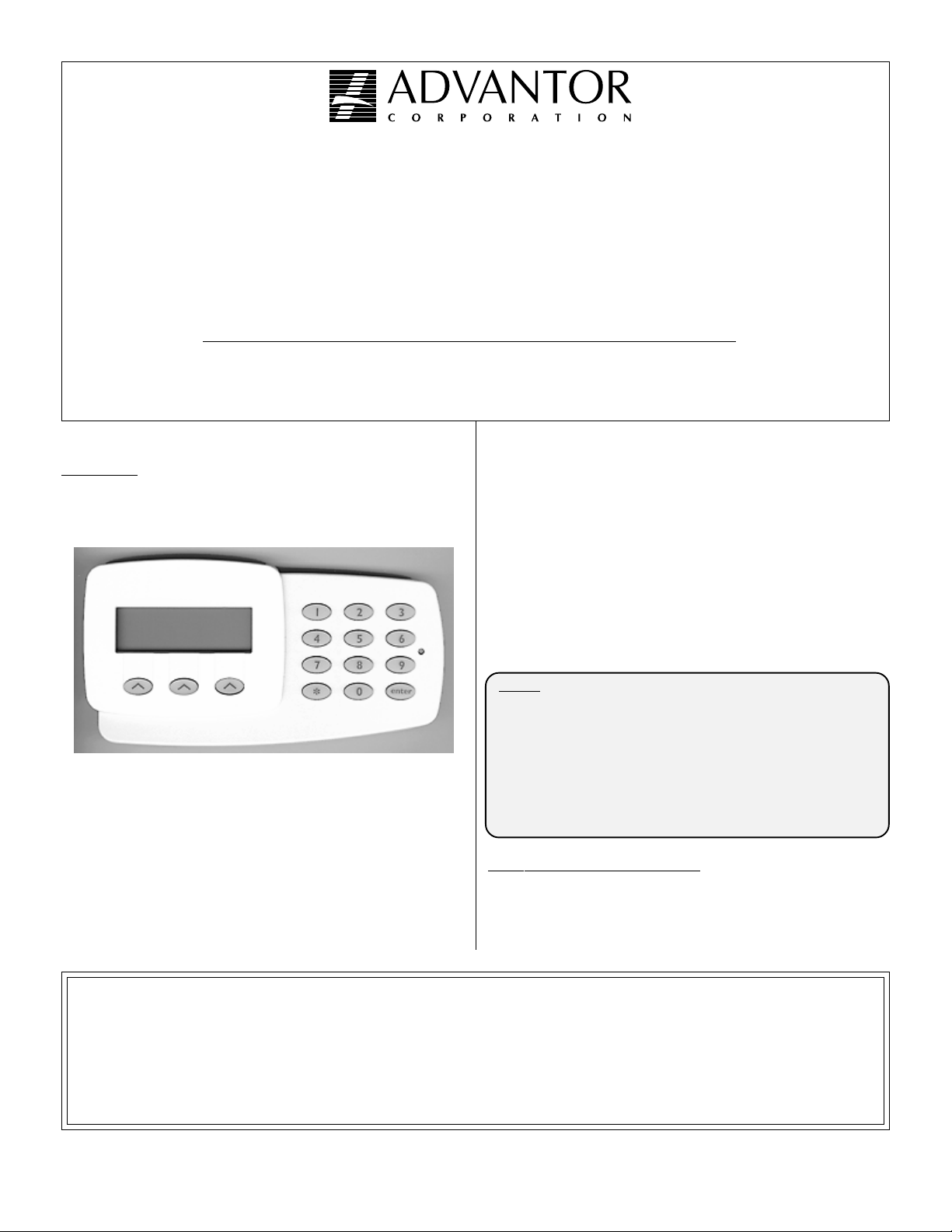
The LCD plus keypad shown in Figure 1 is a 15 button wallmounted keypad in its own enclosure. The keypad contains a four
line, 20 character per line Liquid Crystal Display (LCD) that
displays the system's status in plain English.
Figure 1. LCD plus Keypad
LCD plus keypad arming features include Automatic, Secure
(employee verification), and Automatic No-dial arming/disarming.
The keypad also provides the following user initiated functions:
• Emergency Duress (ambush) alarming
• Intermediate arming with OCCUPIED DELAY or OCCUPIED INSTANT alarm reporting
• Chime Mode
• User assistance request
• Cancel alarm generation
• Auxiliary output control
• On-site test procedure.
The following control panels support LCD plus keypads:
• Advantage plus • ADV 3250
• ADV 3450 • AAM4+
• ADV 3650 • AAM4-C+
• ADV 3475 • AAM4-A
• ADV 3350+ • AAM4C-A
The LCD plus keypad communicates with control panels over the
RS-485 communications bus, much like Advantage Access
Modules.
Jumpers inside each LCD plus keypad assign it with a unique keypad
bus address. (Note that LCD plus keypads can share the same
address with an Advantage Access Module).
NOTE: LCD plus KEYPADS INSTALLED IN UL BUR-
LCD
See the SONICS Database Management Manual or the Advantage
Access for Windows User’s Guide for LCD plus keypad options
programming.
GLARY AND FIRE SYSTEMS SHALL BE LOCATED WITHIN 20 FEET OF THE ALARM ENCLOSURE AND ALL KEYPAD WIRING SHALL BE
ENCLOSED IN CONDUIT.
USING THE ADAPTER PLATE (P/N 09004301)
MOUNT THE LCD plus KEYPAD ON A
STANDARD ELECTRICAL UTILITY BOX TO
ALLOW CONDUIT CONNECTION AT THE
KEYPAD.
plus
KEYPAD OPTIONS
®
®
ADVANTOR CORPORATION HARDWARE LIMITED WARRANTY STATEMENT
Advantor Corporation warrants each new product of its manufacture, to be free from defects in material and workmanship.
It will repair or replace defective parts for a period of 24 months from the date of manufacture, providing the equipment has not been subjected to
abnormal conditions such as misuse, abuse, misapplication, alteration, lightning damage or damage by an Act of God. This excludes packing,
handling and shipping charges from the Customer. The limited warranty is restricted to the original purchaser.
ALL OTHER WARRANTIES, EXPRESSED OR IMPLIED, INCLUDING MERCHANTABILITY, THE FITNESS OF
EQUIPMENT FOR A PARTICULAR PURPOSE OR WITH RESPECT TO CLAIMS OF ANY THIRD PARTY BY THE
WAY OF INFRINGEMENT OR THE LIKE, ARE EXCLUDED.
1
Downloaded from - http://www.guardianalarms.net
Page 2
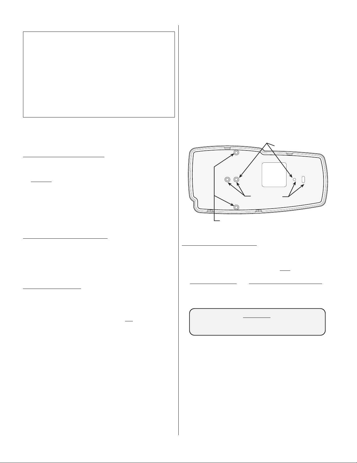
Wiring
Access
Vertical junction box mounting with adapter plate.
Horizontal junction
box mounting holes.
Standard wall
mounting holes.
Table 1. LCD plus Keypad Specifications
ALARMS:
Emergency Duress
Cancel/Disregard
Call Central
SUPERVISION:
Communication loss annunciated
at keypad after 1 minute.
INTERCONNECTION:
Four wires, 300 feet maximum
5Ω maximum line resistance.
OPERATING ENVIRONMENT:
32° F to 122° F / 0° C to 50° C
NOTE 1: This restriction is due to power loss through cabling. With a
remote power supply the RS-485 link can extend up to 2,000
feet.
NOTE 2: 25mA for keypad, plus 20mA for backlighting at the 20%
default.
ENCLOSURE:
4.0" H x 7.275" W x 0.88" D
POWER (from control panel):
9-15VDC
45mA Standby current
25-125mA Alarm current
(programmable)
ARM/DISARM:
1
.
Secure
Automatic
Automatic No-Dial
Single Key Arming
2
CABLING CONSIDERATIONS
The maximum cable run for each LCD plus keypad is 300 feet from
the control panel.
Advantor recommends that you use 22AWG
twisted pair, shielded cable. When running LCD plus keypad cables:
1. DO NOT run cables parallel to AC wiring, unless the AC is in
metallic conduit.
2. Avoid mounting the keypad next to a light switch or electrical
outlet.
3. Keep wires away from fluorescent light fixtures. Fluorescent
lights produce a high level of electrical noise.
4. Keep cables away from high current devices (i.e., motors,
welders, etc.) which might induce spikes into the wires.
REMOVING THE BACK PLATE
The LCD plus keypad has four snaps around the edge of the enclosure. To open the keypad, insert a small screwdriver into one of the
slots and gently turn the screwdriver until the enclosure snap opens.
Move to the next slot and repeat this procedure until the enclosure
opens. Usually only two adjacent snaps need to be opened to remove
the cover.
KEYPAD MOUNTING
WALL MOUNTING
The LCD plus keypad backplate has several mounting hole locations
(see Figure 2). For wall mounting use two of the middle mounting
holes.
Hold the back plate against the wall and mark
holes. Using a level draw a horizontal line through the marked hole.
Place the backplate against the wall again and line up the mounting
holes with the level line and mark the second hole location.
Since the LCD plus keypad does not have a straight edge, using a
level to mark mounting hole locations ensures level keypad mounting.
one of the mounting
JUNCTION BOX MOUNTING
Depending on the orientation of the junction box, the LCD plus has
two sets of mounting holes that can be used for junction box
ing.
You can mount the LCD plus directly to a double or triple gang
mount-
outlet box, however, be aware that the backplate may not completely
cover the box.
To completely cover the junction box use the LCD plus adapter plate
(P/N 09004301).
NOTE: The adapter plate can only be used on a horizontally
mounted junction box. Junction boxes are normally
mounted in the horizontal position. This adapter plate is a
spacer that goes between the junction box and the LCD
plus backplate.
To install the adapter plate line up the mounting holes of the adapter
plate with the LCD plus backplate. Insert two screws through the
backplate and the adapter plate and attach it to the junction box.
Attach the LCD plus keypad to the backplate after completing all
wiring and checks.
Figure 2. LCD plus Keypad Backplate Mounting Holes
LCD
plus
KEYPAD WIRING
Remove the LCD plus keypad Panduit connector and connect the
cable wires into the connector. To ensure proper connections, each
connection is silkscreened on the keypad circuit board.
The keypad connections at the control panel
must match the
connections at the LCD plus keypad. For example:
LCD plus KEYPAD CONTROL PANEL/MODULE
GND 24-Hour GND Source
DATA- DAT-, DATA- or DATALINE -
DATA+ DAT+, DATA+ or DATALINE +
+12V 24-Hour +12VDC Source
WARNING!
REVERSING THE +12V AND GND WIRES WILL
DAMAGE THE KEYPAD. CHECK POLARITY
BEFORE APPLYING POWER.
Table 2 lists compatible control panel and module connections
where you can find the required +12VDC keypad power and ground.
NOTE: Subtract each LCD plus keypad’s 45mA Normal Standby
and 25 to 125mA Alarm current from the control panel’s
backup battery loading chart.
2
Page 3

Table 2. Keypad Power Connections
eludoMrolenaPlortnoCniP-kcaJlebaLgnitaRtnerruC
eludoMesaB9,8,7,6-2J21+1etoNAm006,1
eludoMnoisnapxE
7,5,3,1-1J21+
4,3,2,1-3J21+
2etoN
eludoMnInetsiL21,11-1J21+2etoN
2-6J/5J/4J/3JV21+
6-2JV21+
Am054
4-2J21+2etoN
71-9J/8J/7J/6JDER
41,31-5JV21+
11,01,9,8-7JV+
6,1-4JDER
Am054
Am054
eludoMsseleriW
+C-4MAA/+4MAA
+1PC
)A-4MAA(eludoMsseccA
)detsiLLUtoN(
5-7J*+LEBAm059
6-1J+1XA
+2PC
Am0078-3J1DER
21-3J2DER
2-1JV21+
4-PC
9,5-3JDER
71-4J+1XUA
Am007
91-4J+2XUA
tnerrucgniwardeunitnoctiucriclleB+1PCehtmorfderewopsdapyeK*
)94301890N/P("snoitcurtsnInoitallatsnIsulpegatnavdA"ehttlusnoC:1ETON
.noitacilpparuoyroftnerrucelbaliavamumixamehtrof
.)S-A1V21SPAroeludoMesaB(ecruosrewopnotnadnepeD:2ETON
LCD
.nwodflestisrewop+1PCehtretfa
plus
KEYPAD FAST/SLOW JUMPER
Each LCD plus keypad is shipped from the factory ready for
installation in fast RS-485 applications (Fast/Slow jumper in place).
Refer to Figure 3 and locate the jumper at the bottom left of the LCD
plus keypad’s circuit board.
LEAVE THIS JUMPER IN PLACE when using the LCD plus
keypad with AAM4-A & AAM4C-A access systems
CUT THIS JUMPER when using the LCD plus keypad with the
following:
• ADV 3450* • ADV 3250*
• ADV 3650* • AAM4+
• ADV 3475* • AAM4-C+
• ADV 3350+*
*NOTE: These systems require version 6.0 (or higher)
firmware.
SETTING LCD
plus
KEYPAD ADDRESSES
Assign LCD plus keypad addresses in consecutive order, starting
with Address #1 and
not skipping any addresses:
Alarm Panel Zone A Keypads (0-3)
Alarm Panel Zone B Keypads (0-3)
AAM Module #1 Door #1
AAM Module #1 Door #2
•
•
•
AAM Module #7 Door #4
Table 3 will assist you in setting LCD PLUS keypad addresses.
Table 3. LCD plus Keypad Address Jumpering
Keypa
Addre
Keypad Jumper
#
1 2 4 8 1 2 4 8
Keypa
Addre
Keypad
Jumper#
1 X 9 X X
2 X 10 X X
3 X X 11 X X X
4 X 12 X X
5 X X 13 X X X
6 X X 14 X X X
7 X X X 15 X X X X
NOTE: X = jumper in place.
REV
S/N
90242
CUT
FOR SLOW
JPR
J1
1
1
2
3
2
4
8
GND
4
5
6
7
8
9
10
11
12
13
ADDRESS
JUMPERS
BEEPOUT
+12V IN
-DATA
+DATA
LCD
PLUS
Figure 3. LCD plus Keypad Circuit Board
3
J2
KP2
1
Page 4

For example, a system has two LCD plus keypads in Zone A and
three LCD plus keypads in Zone B. The system also has two LCD
plus keypads on AAM Module #3, Door #2, and one additional
keypad on AAM Module #7, Door #4.
The following shows the LCD plus keypad address scheme in this
sample integrated system:
Address Location
1 Zone A Keypad #1
2 Zone A Keypad #2
3 Zone B Keypad #1
4 Zone B Keypad #2
5 Zone B Keypad #3
6 AAM #3, Door #2
7 AAM #3, Door #2
8 AAM #7, Door #4
External Beeper Output
NOTE: UL requires that there be NO CONNECTION to this
output, which goes low while the keypad is beeping.
Pressing the Status button displays the system status. Displayed
status messages may include:
Pressing the Quit button returns you to the initial Setup Mode
screen (Figure 4).
Pressing the Loops button
displays the status of
system alarm loops (open,
shorted, normal). The
word “tested” appears in
the display if the loop was
tested during a Walk Test
(see Figure 7 for an
example).
While viewing the Loop Status screen pressing Prior displays the
previous alarm, pressing Next displays the next alarm.
Pressing Quit returns you to the Setup Mode screen (Figure 4).
• low battery • RPU down
• memory error • options error
• preamp down • cut telephone line
LOOP STATUS
Loop # 16 shorted
tested
Prior Quit
Figure 7. Loop Status Screen
LCD
plus
KEYPAD SETUP MODE
NOTE: Only LCD plus keypad #1 operates while the system is in
Place a system with no options into the Test Mode by powering it up
with the TEST/OPER switch (S1) in the TEST position.
NOTE: 3350+ and 3250 systems enter Test Mode by powering up
The keypad displays a
“Waiting for Master
Controller” message.
After approximately 15
seconds the LCD plus
keypad displays the Setup
Mode screen shown in
Figure 4, indicating the
system is in the Test Mode.
NOTE: Cal displays on only 3350+, 3450 and 3475 systems. The
the Test Mode.
with the Tamper loop violated. After power up press
“9+8+7+6+ENTER” on the keypad to stay in Test Mode.
SETUP MODE
HHMM ENTER sets time
select function
Test Cal Download
Figure 4. LCD Setup Mode Screen
3250 system and access modules have no audio detection
capabilities.
SETTING SYSTEM TIME
Any time the LCD plus keypad displays the “HHMM ENTER sets
time” prompt you may set or change the system clock. Using
military time format (i.e., HH=Hours, MM=Minutes, 4 pm = 16:00
hours), enter the current time then press ENTER. The keypad triple
beeps showing the system has accepted the change.
LCD
plus
KEYPAD TEST MODE
From the Setup Mode
s
creen, pressing the Test
button displays the Test
Mode screen shown in
Figure 5. The Test Mode
screen offers the following
system tests:
• Walk Test
• Auxiliary Output Test
• Audio Test
Walk Outputs Audio
Figure 5. System Test Screen
TEST MODE
press * for status
select function
System Status (*)
From the System Test
screen you can check the
system status at any time by
pressing the keypad “*”
key. Pressing “*” displays
the STATUS screen in
Figure 6.
select display
Status Quit Loops
Figure 6. Status Screen
Walk Test
From the Test Mode
screen, pressing the Walk
button places the system in
the Walk Test Mode and
displays the WALK TEST
screen shown in Figure 8.
Using Walk Test you can perform a functional system test by
entering Walk Test then walking around the facility violating alarm
loops. Each loop violation and restoral sounds the local bell for 1
second.
After violating the loops return to the keypad and press ENTER to
exit the Walk Test. The System Test screen in Figure 5 reappears.
You can press the keypad “*” key (system status) to see the Walk
Test results. Pressing “*” displays the TEST RESULT screen shown
in Figure 7.
Outputs Test
From the Test Mode
screen (Figure 5), pressing
the Outputs button
displays the OUTPUTS
TEST screen shown in
Figure 9.
Pressing the associated keypad key toggle the outputs on and off.
Press the number key to turn each output on, and press it a second
time to return the output to its original state.
• “1” for Aux Output #1 • “4” for Aux Output #4
• “2” for Aux Output #2 • “5” for the local bell
• “3” for Aux Output #3
OUTPUTS ON: 1 2 3 4 BELL
toggle by entering
aux # or 5 for Bell
Figure 9. Outputs Test Screen
Audio Test
From the Test Mode screen
(Figure 5), pressing the
Audio button displays the
AUDIO TEST screen shown
in Figure 10.
In addition to displaying
the Audio Test screen, pressing the Audio button automatically
sends a test tone to all audio sensors.
NOTE: Stored audio is not available on 3250 and access systems.
Ring Audio Done
WALK TEST
in progress
push ENTER when done
Figure 8. Walk Test Screen
push ENTER when done
AUDIO TEST
select function
Tip Stored
Figure 10. Audio Test Screen
4
Page 5

Tip Ring Audio TestTip Ring Audio Test
Tip Ring Audio Test
Tip Ring Audio TestTip Ring Audio Test
From the Audio Test
screen, pressing the Tip
Ring button displays the
TIP/RING AUDIO TEST
screen shown in Figure 11.
Using the Tip/Ring Audio
Test you can route audio to the TIP and RING test points on the
panel. Connecting a handset to these test points allows you to check
the quality of the audio that will be sent to the central station.
With the phone line disconnected, pressing the On button routes
audio from all system audio sensors to the TIP and RING test points
on the panel.
Pressing the Off button removes the audio from the TIP and RING
test points.
Pressing the Done button returns you to the initial Setup Mode
screen (Figure 4).
Stored Audio TestStored Audio Test
Stored Audio Test
Stored Audio TestStored Audio Test
From the Audio Test
screen, pressing the
Stored Audio button
displays the STORED
AUDIO TEST screen
shown in Figure 12.
NOTE: Stored audio is not available on 3250 or access systems.
With the phone line disconnected, pressing the Store button forces
the panel to store the next 5 seconds of audio.
Pressing the Replay button routes the stored audio to the TIP and
RING test points on the panel. Connecting a handset to these test
points allows you to check the system’s audio storage circuitry and
the quality of the audio that will be sent to the central station.
Pressing the Done button returns you to the initial Setup Mode
screen (Figure 4).
LCD
plus
KEYPAD CALIBRATION MODE
From the Setup Mode screen, pressing the Cal button displays the
Audio Calibration screen shown in Figure 13. The Audio Calibration Mode screen offers
the following calibration
modes:
• Auto
• Manual
• View
Auto CalibrationAuto Calibration
Auto Calibration
Auto CalibrationAuto Calibration
NOTE: See the Advantage 3000 Series Systems Installation and
From the Calibration
Mode screen, pressing the
Auto button places the
system in the Automatic
Calibration Mode and
displays the Calibration
screen in Figure 14.
From the calibration screen select any audio detectors that you want
to exclude from the calibration. This screen displays the excluded
audio detector number(s) as they are entered on the keypad.
Pressing the Quit button returns you to the Calibration screen
(Figure 13).
Pressing the Start button
displays the Auto Calibra-
tion screen shown in
Figure 15.
Service Manual for detailed Automatic audio calibration
procedures.
TIP/RING AUDIO TEST
select function
On Off Done
Figure 11. Tip/RingAudio Test Screen
STORED AUDIO TEST
select function
Store Replay Done
Figure 12. Stored Audio Test Screen
AUDIO CALIBRATION
select function
Auto Manual View
Figure 13. Calibration Screen
select detector #s
to exclude
excluded:
Start Quit
Figure 14. Calibration Mode Screen
AUTO CALIBRATION
calibrated: 12345678
excluded:
Done
Figure 15. Auto Calibration Screen
The Auto Calibration screen “calibrated” listing shows the audio
detectors that have been calibrated. This listing updates as
detectors are calibrated.
Using the Calibration Mode screen View command, check the
detector(s) sensitivity (see View Calibration).
Pressing Done returns you to the Calibration Mode screen (Figure
13).
View CalibrationView Calibration
View Calibration
View CalibrationView Calibration
From the Calibration
Mode screen, pressing the
View button places the
system in the View Mode
and displays the View
screen in Figure 16.
While viewing the screen pressing Prior displays the previous
audio detector, pressing Next displays the next detector.
Pressing Quit returns you to the Setup Mode screen (Figure 4).
Manual CalibrationManual Calibration
Manual Calibration
Manual CalibrationManual Calibration
NOTE: See the Advantage 3000 Series Systems Installation and
From the Audio Calibration screen, pressing the
Manual button places the
system in the Manual
Calibration and displays
the Manual Calibration
screen shown in Figure 17.
Pressing the Cal button displays the second Manual Calibration
screen shown in Figure 19 and enables all audio detection circuits.
While the keypad displays this screen you can manually adjust the
sensitivity pots on audio sensors without affecting the audio
detector settings.
Entering a valid audio
detector number (or
pressing “0” for all
detectors) displays the
Sensitivity screen shown in
Figure 18.
Pressing the numbers (00-
15) corresponding with the
desired sensitivity and
pressing ENTER displays
the second Manual
Calibration screen shown
in Figure 19.
Using the Audio Calibration screen View command, check the detector(s) sensitivity (see View Calibration).
Pressing ENTER returns you to the Audio Calibration screen
(Figure 13.)
LCD
From the Setup Mode
screen, pressing the
Download button displays
the Download Mode
screen shown in Figure 20.
The Download Mode
screen offers Answer, Call
and Quit options.
Service Manual for detailed Automatic audio calibration
procedures.
plus
KEYPAD DOWNLOAD MODE
Figure 16. Manual Calibration Screen
select detector no.
Figure 17. Manual Calibration Screen
select function
Answer Call Quit
Figure 20. Download Mode Screen
Audio Calibration
Detector number: 1
Sensitivity: 06
Prior Quit Next
MANUAL CALIBRATION
(or “0” for all)
Cal
select sensitivity
from “00 (off) to
“15” (most sensitive)
push ENTER when done
Figure 18. Sensitivity Screen
Audio Calibration
Tripped: 1
Select function
Auto Manual View
Figure 19. Manual Calibration
Screen #2
DOWNLOAD MODE
5
Page 6

Answer ModeAnswer Mode
Answer Mode
Answer ModeAnswer Mode
Use the Answer Mode when you contact the central station and
request an options download. While in the Answer Mode the panel
seizes the line and answers the phone (goes off-hook) on the first
ring.
From the Download
Mode screen, pressing the
Answer button places the
system in the Answer
Mode and displays the
screen in Figure 21.
The Exit button gives you
the option of exiting Download Mode and returns you to the initial
Setup Mode screen (Figure 4).
While at the Answer Mode screen, restoring the Tamper loop (3250
and 3350+ systems) or switching the panel’s TEST/OPER switch
(S1) back to OPERATE (3450, 3475 and AAM4-C+) prepares the
panel for options downloading.
The keypad screen clears, then a “Waiting for download” message
appears on the bottom display line until the central station computer
contacts the panel. Once the download begins the keypad display
changes to a “receiving download” message. After completing the
download the keypad displays the main screen shown in Figure 4.
Call ModeCall Mode
Call Mode
Call ModeCall Mode
Use the Call Mode to
initiate the options
download from the LCD
PLUS keypad at the
control panel location.
From the Download Mode
screen, pressing the Call
button places the system in
the Call Mode and displays the Call Mode screen shown in Figure
22.
NOTE: The Quit button in all Download screens gives you the
option of exiting and returning to the initial Setup
Mode screen
(Figure 4).
From the Download Mode
screen, pressing the Enter
Options button displays
the screen shown in Figure
23.
Pressing the Quit button
returns you to the Call
Mode screen (Figure 22).
Use this screen to enter the
information required to
begin the download. This
includes the central station
telephone number.
Pressing the Enter Phone# button displays the screen shown in
Figure 24.
Enter the phone number you want the panel to call. Pressing the
Delay button anywhere in the phone number inserts a three second
select function
Options Dial Quit
select function
Phone# Acct# Quit
Figure 23. Download Mode Screen
Enter phone# to call
Restore Tamper
Switch to operate
Exit
Figure 21. Answer Mode Screen
DOWNLOAD MODE
Enter
Figure 22. Call Mode Screen
DOWNLOAD MODE
Enter Enter
DOWNLOAD MODE
Delay Done
Figure 24. Phone# Screen
delay before continuing the
dialing sequence.
Press Done after entering
the phone number.
Pressing the Enter Acct#
button displays the screen
shown in Figure 25 and
allows you to enter the optioned account number (see the options
sheet).
Pressing the Quit button returns you to the Call Mode screen
(Figure 22).
Dial ModeDial Mode
Dial Mode
Dial ModeDial Mode
Use the Dial Mode to
force the control panel to
dial the central station.
From the Download Mode
screen, pressing the Dial
button places the system
in the Dial Mode and displays the Dial Mode screen shown in Figure
26.
While at the Dial Mode screen, restoring the Tamper loop (3250 and
3350+ systems) or switching the panel’s TEST/OPER switch (S1)
back to OPERATE (3450, 3475 and AAM4-C+) prepares the panel
to dial for options downloading.
The keypad screen clears, then a “Calling for download” message
appears on the bottom keypad display line. Once the download
begins the keypad display changes to a “receiving download”
message.
After completing the download the keypad display automatically
returns to the main screen shown in Figure 4.
DOWNLOAD MODE
Enter panel account#
Push ENTER when done
Figure 25. Account# Screen
Restore Tamper
Switch to operate
Exit
Figure 26. Dial Mode Screen
COMMUNICATION LOSS
The LCD plus keypad senses a loss of communication with the
control panel and annunciates the loss. One minute after communication loss the keypad alerts the user by beeping once each 10
seconds.
The beeping continues until the user presses any key, at which time
the beeping stops and displays a “System Down Call for Service”
message. The message remains until communications restore.
UL WARNING!
LCD plus KEYPADS WITH A BLINKING YELLOW
LED, A BLINKING CURSOR AND BEEPING EVERY 10
SECONDS INDICATES AN RS-485 COMMUNICATIONS
PROBLEM. THE SYSTEM MAY BE INCAPABLE OF
REPORTING FIRE OR BURGLARY ALARMS.
6
 Loading...