

Page 1

AV 60
AUDIO
VERIFICATION
UNIT
Downloaded from - http://www.guardianalarms.net
Page 2

CONTENTS
Page
INTRODUCTION 3
SYSTEM OVERVIEW 4
CONNECTION DETAILS 5
SYSTEM FEATURES EXPLAINED 6
PROGRAMMING 8
MICROPHONE UNIT 10
CONTROL TONES 11
SYSTEM REQUIREMENTS 12
STATUTORY REQUIREMENTS 12
CONNECTION REQUIREMENTS 13
INSTALLATION REQUIREMENTS 14
APPLICATION NOTES 15
LT268 Issue 1.0
Page 3

2
Introduction
The Audio Verification Unit (PR107) is designed to enhance security alarm systems by adding
audio verification without changing the existing control panel.
It has been designed to be used with either standard digital communicators ,Red care,
Modems or as a standalone device.
Features
Eight microphone inputs each capable of using 4 microphones.
Audio expander (sold separately) providing up to 128 microphone capability
Audio storage circuit capable of storing up to 30 seconds of audio.
Output to provide visual indication of "microphones active"
Relay contacts (rated at 1 Amp 12V DC)
Two switched outputs (controlled from C/S)
Full duplex two way talk
Broadcast Facility
Part set Facility
Site announcement message
Function acknowledgement messages
Site access pass code
Full on site programming and test.
B.T Star (network) services to remove bar on incoming calls.
Remote facilities (from monitoring station)
Each microphone input can be individually switched on or off when "live".
Auto switch through each input for 2 seconds.
Switch between live and recorded audio.
Extend “on line” time (normally 2 minutes).
Shutdown audio
Pulse relay for approx. two seconds.
Switch relay on/off..
Enter pass code to access audio from site.
Talk back to site live.
Broadcast a live message to site.
Playback site message (description of site in use).
Pulse output 1 or 2 for approx. two seconds.
Switch output 1 or 2 on or off..
Programmable options
Select recording only after alarm activated.
Select recording only after alarm system is set
Select negative or positive control input.
Enable or disable B.T Star services.
Select recorded or live audio first when dialling back into site.
Select relay auto switch when connected to central station or controlled by C/S
Record site announcement message
Enable / disable and enter pass code
Enable / disable communication successful for Digicomm
Page 4

3
SYSTEM OVERVIEW
Before the operation of the unit is described, it is essential to understand three
fundamental features.
Audio Verification.
Audio verification is achieved by connecting microphones, fitted throughout a protected premises, to
the AV Unit.
The AV Unit is connected to an existing alarm system which provides it with information on the alarm
status ( set, alarm, communication successful)
When an alarm is triggered the alarm signal is sent to a central monitoring station via
the Digital Communicator, Red care or Modem (existing equipment as part of the alarm system)
Once the monitoring station has received and acknowledged the alarm signal they will
then dial back in to the site using a standard telephone and the AV Unit will then provide
a "Listen in" facility.
The AV unit will NOT provide Alarm Detection or Alarm Signalling
The Central station will have a series of facilities to help them identify if the alarm is false or if the site
requires policing.
Each central station will have there own particular procedures for dealing with audio verification and
you should consult your central station for details.
The AV unit has the ability to comply with every existing procedure, you will have to program the unit
in specific ways to comply with the requirements of some central stations (see application notes)
Page 5
4
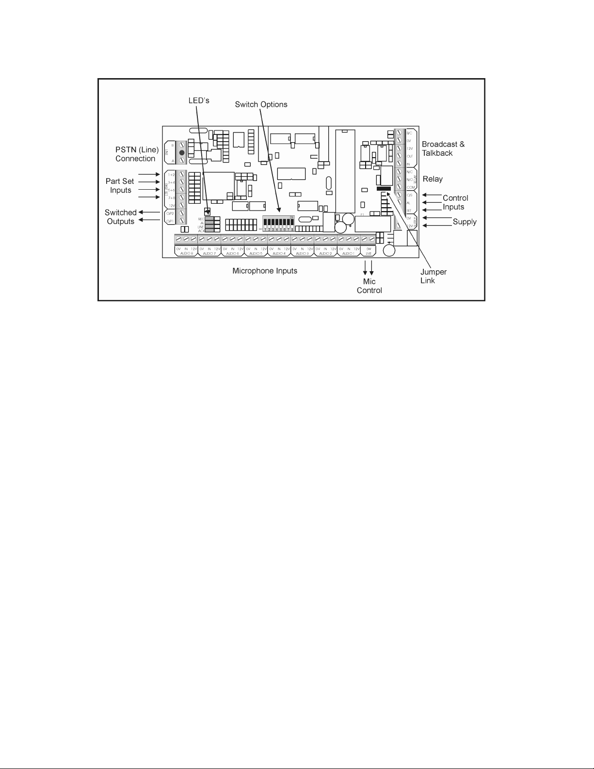
Connection Details
Control Inputs
SET The SET terminal is used to start the recording cycle, when input is activated the
recording starts ( Option Switch 2 must be “ON”)
AL The Alarm trigger is used to activate the system.
C/S The Communication Successful input is used for confirmation that the alarm
signalling equipment has communicated its’ alarm signals successfully.
(A C/S output is available from most “Digicoms” )
Note : The AV60 will only answer an incoming call when the AL input is active.
Microphone Inputs
There are eight Audio Input channels, each provides a fused +12V and 0V supply to the
Microphone Units (PR086) and receives the audio input from these units.
SW Live The switched live outputs are active if the unit is recording or during live audio.
Relay “Clean” changeover relay contacts rated 1A at 12V).
Outputs Two open collector outputs O/P1 and O/P2 rated at 100 mA (+12v switched to 0v)
Part Set There are four part set inputs, each input controls two audio channels.
Broadcast/Talkback For interface to the AV60 Broadcast or Talkback units (available separately)
LINE For connection to the PSTN
Page 6

5
System Features Explained
Audio Recording.
The A.V Unit can Record 30 seconds of audio received from all microphone inputs.
When an alarm is triggered the A.V unit will store half the time programmed before the
alarm and half the time programmed after the alarm, IE 15 seconds pre and 15 seconds
post alarm. (this facility will only function if the AV unit is programmed to record
after the system is set. The recorded audio can be replayed by the central station during alarm
condition.
There are two modes of operation for recorded audio.
1: The unit can be configured to start recording when the system is set.
2: The unit can be configured to start recording when in alarm condition.
Audio Switching.
There are eight microphone inputs on the AV Unit.
When the monitoring station is "listening in" these inputs can be individually switched
ON or OFF to allow background noise to be eliminated.
B.T Star Services.
The unit has the capability to use the star services to add or remove a bar on incoming
calls this is used when the line is shared with a digital communicator or modem.
Relay
The relay can be either controlled from the Central station or it can be programmed to
switch when the AV unit receives an incoming call, this can be used to silence local sounders.
There are Four modes of operation.
1: Auto switch relay after answering a call (auto switch back after
shut down)
2: Pulse for approx. two seconds (central station control)
3: Switch ON ( Central station control).
4: Switch OFF (Central station control)
Switched outputs
The switched O/P’s operate in the same way as the relay (except auto switching).
1: Pulse for approx. two seconds (central station control)
2: Switch ON ( Central station control).
3: Switch OFF (Central station control)
Talkback
With the AV60 Two way talk is possible (talkback). To use this facility refer to the
instructions provided with the AV60 Talk back unit.
Page 7

6
Broadcast
An output is provided to allow the central station to directly talk to the site through loud
speakers (AV60 Broadcast speaker system).
Part Set
The 4 part set inputs are used to enable 4 pairs of microphone inputs,
The polarity and control of these inputs is programmed by SW1 switch 1 (see page 8)
This facility can be used to provide a system with area setting facilities or, if used in a domestic
system, a night set facility.
Site Announcement
The AV unit has the facility to record on site an announcement which is then replayed when the
central station dial in to the site. This acts as a conformation that they are listening to the
correct site. The announcement can be up to 10 seconds long.
Function Announcement
The A.V unit has pre-recorded function announcements, these provide verbal conformation to
the central station operators that the function they have selected is now in operation. I.E. when
the central station selects replay recorded audio, the message "STORED" will be played before
the actual recorded audio is played. This will provide evidence that the central station carried
out a particular function as all calls are recorded at the central station.
Site Access Pass Code
The AV Unit has the ability to use a pass code which must be entered by the central station
before they can gain access to the audio on site. The pass code function is normally disabled
to use this facility refer to "programming" on page 9.
The pass code will be retained even if the power is removed from the AV unit and can only be
programmed or changed “on site”
LED Indicators
There are 4 LED’s to provide information regarding the status of the AV60 Unit during the
various operating sequences.
REC Indicates when the unit is recording.
AL Indicates when the unit has been activated by the alarm.
LINE Indicates the unit is “on Line” or in Commission mode
ACK Indicates that the first control tone has been accepted and is now waiting for the second
tone.
Page 8

7
Programming
The AV unit can be programmed on site by using the option switches fitted to the unit.
SW1
No Option ON OFF
1 Input Type Positive Negative
2 Recording Start on SET Start on ALARM
3 Relay Remotely Controlled Auto switched on “Answer”
4 Star Services Not in use Active
5 Audio sequence “Live” audio on answer “Stored” audio on answer
6 C/S Not Used Active
7 Not used
8 Test Mode Off Test mode
Since the outputs available from Alarm Control Panels are varied, the AV60 can be programmed for
control by either positive or negative voltages.
The “Jumper link” is used to select either pull up (to 12v) or pull down (to Gnd) Control inputs
Switch 1 Provides the option to activate the Control Inputs by applying +ve or –ve voltages.
Control Panel Outputs Switch 1 Jumper link
Switched to +12V on activation ON Pull Down
Normally +12v, removed on activation OFF
Pull Down η
Switched to 0V on activation OFF Pull Up
Normally 0V, removed on activation ON
Pull Up η η
Note : η Any unused Part Set Inputs must be linked to +12v
η η Any unused Part Set inputs must be linked to 0V
Switch 2 Selects the recording Start Time
ON Records all the time while the system is SET
OFF Starts recording only when an alarm as activated.
Page 9

8
Switch 3 Selects how the Relay is to be controlled
ON Controlled remotely by the monitoring station using DTMF Tones
OFF Automatically switches when AV60 answers incoming call
(refer to page 6)
Switch 4 Selects the use of BT Star Services. (refer to page 6)
ON Star Services not in use
OFF Star Services enabled
Switch 5 Selects the audio available to the monitoring station immediately the AV60
answers following their Dial up and “listen in” to site.
ON All channels open and listening to Live Audio.
OFF Listening to stored Audio for 30 seconds.
Switch 6 Disables the requirement for a Communication Successful confirmation.
ON No C/S connection required. (e.g. when used with “Redcare”)
OFF C/S confirmation required.
Switch 7 not used.
Switch 8 Selects Test/commissioning mode.
ON Normal operation
OFF Unit in “Test Mode”.
Commissioning
Note : Unit must not have AL or Set inputs activated (i.e. Check No LED’s illuminated)
Plug a DTMF handset into the unit.
Enter Test Mode - Switch 8 to OFF. The LINE Led will illuminate.
The unit can now be exercised by simulating the Central Station functions (refer to Page 11)
Exit Test Mode - Switch 8 to ON. The LINE Led will extinguish.
The following are the operations only available at site :-
To Record site announcement message
1: Press 0 2 on the handset (The REC Led will come on)
2: Record message (up to 10 seconds)
3: The REC Led will go out after the recording time has expired or a button has been
pressed to end the recording.
4. The unit will now store the site message into memory and beep when it is finished.
5. The message will now be played back for confirmation.
Enable Pass code
1: Press # 7 on the handset
2: Enter th e 4 d i g it code e.g. 1 2 3 4
3: Press η
Disable Pass code
1: Press # 7 on the handset
2: Press #
3: Press η
Page 10

9
MICROPHONE UNIT
(PR086)
Features
Detect LED : This led illuminates as the unit responds to audio detection
(primarily used for commissioning)
Live LED : This led is illuminated when the AV Unit is in "listen in" mode and
cannot be disabled by the user.
Connections
0V, Out, 12V : connected to 0V, Audio in and 12V of Audio channel of AV Unit
Active Input : connected to "SW WHEN LIVE" terminals of AV Unit.
note : failure to make this connection will invalidate the approval status of this unit
Tamper : connected in series with security system tamper loop.
Note : The Microphone Unit is not adjustable. The "Gain" of each unit has been factory set.
It is therefore important that the location of each unit to be installed is carefully considered such
that it provides the optimum performance.
Specification
Operating Voltage : 9 to 15V d.c.
Operating Temperature : 0 - 40 deg.C
Quiescent Current (Leds off) : 5mA (nominal)
Quiescent Current (Leds on) : 15mA (nominal)
Tamper (Clean contacts) : rating 50mA (at 12V d.c.)
Microphone : Omni- directional
Frequency Range : 50Hz - 10KHz
Dimensions : 55 x 65 x 50mm
Weight : 50g
Page 11

10
Control Tones
Tone Function
γγγγ 0
γγγγ 1
γγγγ 2
γγγγ 3
γγγγ 4
γγγγ 5
γγγγ 6
γγγγ 7
γγγγ 8
γγγγ 9
All channels on
Channel 1 only
Channel 2 only
Channel 3 only
Channel 4 only
Channel 5 only
Channel 6 only
Channel 7 only
Channel 8 only
Auto Sequence All
# 1 Replay Stored Audio
# 2 Extend time by 2 mins
# 3 Shut Down
# 4 Pulse Relay for 2 secs
# 5 Relay On
# 6 Relay Off
# 7
0 0
Enter Passcode η
Talkback
0 1 Broadcast
0 2
Record Site Message η
0 3 Playback Site Message
0 4 Output 1 Pulse
0 5 Output 1 On
0 6 Output 1 Off
0 7 Output 2 Pulse
0 8 Output 2 On
0 9 Output 2 Off
η Only available as on-site programming feature.
Page 12

11
SYSTEM REQUIREMENTS
Always refer to reference manual of host equipment before connection
The Audio Verification unit is primarily controlled by the security system.
i.e unless the system is in an alarm condition, no "listen in" facility can be initiated.
Host equipment
Please ensure that the host equipment (i.e control panel) in which the AV Unit
is to be situated is covered by either a relevant Type Approval of its own or
states that the General Approval NS/G/1234/J/100003 applies
note : should the host equipment display neither statement then it is not
approved.
Signalling Equipmen t
The digital communicator or Modem can be any approved type that has the facility to provide a
Communication Successful output.
Microphone unit
The microphone units must be of a type specified as suitable for use with the AV Unit. (i.e.
AV Microphone Unit PR086)
STATUTORY REQUIREMENTS
Mandatory Statement
Any modifications to this Audio Verification Unit not authorised will INVALIDATE its approval
for connection to the Public Switched Telephone Network.
Power Supply
The AV Unit derives its power from the host equipment. (e.g.security system control panel)
It is a condition of approval that the total power required by the host equipment plus all
connected ancillary equipment does not exceed the total power provided by the host
equipment.
The power requirements for the AV Unit are :
10-15V d.c. at 70mA (maximum at 15V)
The power requirements of the Microphone unit are :
10-15V d.c. at 15mA (maximum at 15v)
Please ensure that the total power available is not exceeded. (Refer to host specification)
NEVER connect mains voltages to the AV Unit
Ringer Equivalence Number (REN)
The REN values appearing on apparatus indicates to the customer maximum number of
apparatus that could be simultaneously connected to a single telephone line without affecting
their ringing characteristics.
The sum total of the REN values should be not more than 4
The AV Unit has a REN value of 1
note : BT Telephones are assumed to have a REN value of 1 unless otherwise stated
Page 13

12
Suitability for use
The AV Unit is suitable for household, office and similar indoor use when connected to
direct exchange lines using Loop-disconnect or Multi-frequency dialling.
It is not suitable : (i) as an extension to a payphone (ii) for use on shared services or a
leased line system.
Note : Apparatus is treated as connected directly to the PSTN line if it is connected to
the PSTN via a Relevant Branch System (RBS). For definition of an RBS refer to
BS6789 Section 6.1, Clause 2.4
Note : The AV Unit is not intended to be used to answer naive callers.
A naive caller is a caller with no special knowledge of the characteristics of the auto-
answering system who would not have reason to expect an answer to be unusually
delayed or who would be uncertain how to act without guidance from the answering
system. (Refer to BS6789 Section 3.2, Clause 2.6)
CONNECTION REQUIREMENTS
Safety
All terminal connections are SELV (Safety extra-low votage) type circuits and only SELV
type circuits must be connected to these ports (for definition refer to EN60950 : 1992
clause 2.3)
Supply
The AV Unit requires a Fused (1A) nominal 12V d.c. supply to terminals marked
SUPPLY observing polarity. (see Statutory Requirements on page 7 for further details of
power supply conditions)
Page 14

13
INSTALLATION REQUIREMENTS
In order to maintain the independent approval of this unit, it must be installed such that clearance and
creepage distances shown in the table below are maintained between
The unit and any other assemblies that either use or generate a voltage shown.
Clearance
Xmm
2.0 2.4 (3.8) Up to 50V rms or Vdc
2.6 3.0 (4.8) Up to 125V rms or Vdc
4.0 5.0 (8.0) Up to 250V rms or Vdc
4.0 6. 4 (10.0) Up to 300V rms or Vdc
Note :
The Creepage distance is the shortest path between two conductive parts , or between a conductive
part and the surface of the enclosure measured along the surface of the insulation
The Clearance distance is the shortest distance between two conductive parts or between a
conductive part and the enclosure surface of the equipment measured through air.
The larger distance, shown in brackets, applies where the environment within the host is subject to
conductive or dry non-conductive pollution which could become conductive due to condensation.
In order to avoid any doubt, with regards to ensuring the AV Unit approval status is maintained, It is
recommended that the unit is mounted in the main security panel in
such a way that no control cards, expansion cards, power supplies etc. are within
10mm of its outer limits (see Fig 4)
Creepage
Ymm
Voltage used or Generated
by Host or other Cards
Fig 4
Important : Where installation of the unit is required in a host which uses or generates voltages
greater than 300V rms or d.c., advice from a competent telecommunications safety
engineer must be obtained before installation.
Page 15

14
Application Notes
Galaxy Range – Connection Details
Control Inputs must be set for positive applied voltages.
i.e. SW1 switch 1 On
Jumper set for “Pull Down” (as factory setting)
Page 16

15
 Loading...