

Page 1

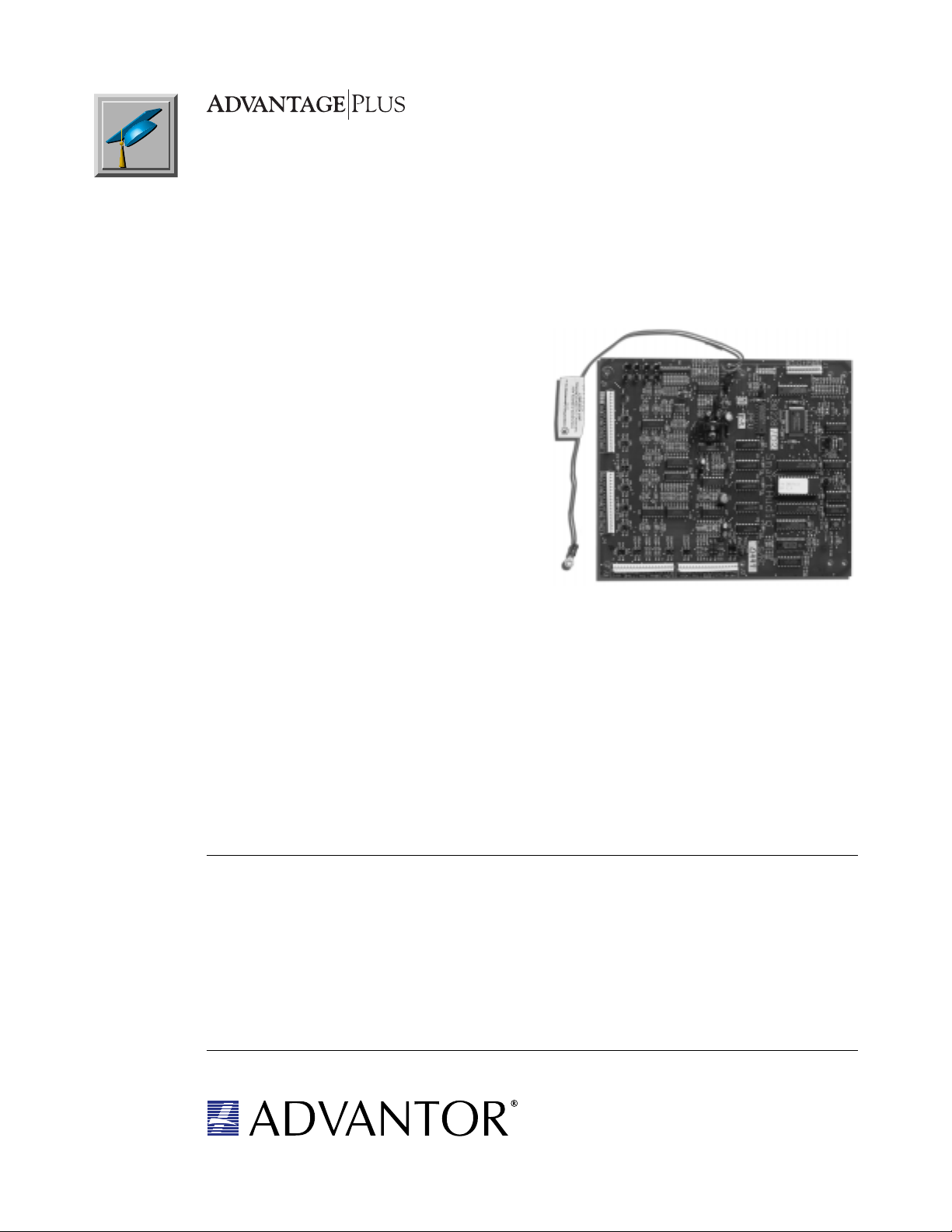
Base Module
The Advantage® plus Base Module is the primary communication processor and control unit for
Advantage plus systems. Installed within the protected facilities, it is available in a standard UL version,
attack version, or a military J-SIIDS version. It interfaces with all other optional modules and devices, and
provides communication with the Advantor integrated monitoring system to transmit and display all
security messages from the facility. It also includes listen back
audio verification for up to four audio inputs.
Dimensions
Standard UL Enclosure
• 17.25” W x 14.5” H x 3.25” D ( 43.82cm x 36.83cm x
8.26cm)
• 20 gauge cold rolled steel with lock and key
• Color: Light gray w/ Advantor logo
Attack-Rated UL Enclosure
• 17.25” W x 14.5” H x 3.25” D ( 43.82cm x 36.83cm x
8.26cm)
• 18 gauge cold rolled steel with lock and key
• Color: Light gray w/ Advantor logo
PCB Foot Print
• 8.5" W x 7.54" H (21.59cm x 19.15cm)
J-SIIDS Compatibility
• Direct replacement for current J-SIIDS applications
• PCB is a replacement for the current transmitter and
processor in conversions
Alarm Points
• 16 programmable, supervised, hard-wired points
• N/C, N/O, or Both (dry contacts)
• Programmable alarm codes
• Assignable to any of 8 separate arming partitions
(protected areas)
• All alarm points operate normally under ground
fault conditions
• Expandable to a total of 144 points with Expansion
Modules & another 63 points with the Wireless
Module
Local Annunciation
• Local bell drive: 12V at 1.25 Amp maximum
• Audible keypad beeper
T ransmission Media
Dedicated
• UL Grade AA, upgradeable to DES Class A
• Supervision for Compromise, and Failure
Dial
• Pulse or DTMF dialing
• Integrated cut line supervision
• RJ31X jack connection
• Secondary dial line capability with optional TelPlus
Module
• Secondary cellular communication with optional
Cellular Module
• Optional Telco “Level 2” Surge Protection
AA
VR PLUS BASE-C shoVR PLUS BASE-C sho
A
VR PLUS BASE-C sho
AA
VR PLUS BASE-C shoVR PLUS BASE-C sho
wnwn
wn
wnwn
Arm/Disarm Function (Secure/Access)
• 16 keypads
• 8 partition capability
• Programmable switch arming via momentary contact
• Programmable access card arming via integrated
• Programmable arm/disarm functions
• Optional SCIF package
P/N 09820481, Rev. A
6/98
Audio
• Four balanced audio inputs supporting four
verification audio sensors or any combination of up to
eight optional SmartAudio or ListenIn Modules for up
to 128 audio inputs.
Wiegand Input
• Interfaces with one card reader or biometric device for
secure, user-friendly arm/ disarm of security and
access control verification for up to 100 users. Access
Modules may be added to the system to extend the
capabilities to upto 10,000 users.
Specifications and part numbers are subject to change without notice.
Downloaded from - http://www.guardianalarms.net
closure
card reader input (wiegand)
• Single key arming
• Non-reporting
• Reporting
• Arm at shift
6101 Lake Ellenor Drive • Orlando, Florida 32809
Tel: 800/ADVANTOR • 407/859.3350 • Fax: 407/859.5205
http://www.advantor.com
Page 2

Operating Envir onment
• 0° F to 122° F (-18° C to 50° C)
Auxiliary Outputs
• Four, 100mA, programmable hard-wired
• Expandable to 36 total with Loop Expansion Modules
Primary Power Options
• 100 to 120 VAC, 60Hz, using 16.5 VAC, 50VA, Class
2 plug-in transformer
• 100 to 120 VAC, 50- 60Hz with internal transformer
• 200 to 240 VAC, 50-60Hz with internal transformer
• Can utilize existing J-SIIDS Power Supply
• Optional AC “Level 2” Surge Protection
Secondary Power
• 12VDC, 7AH, sealed lead-acid rechargeable batteries
(1 or 2, depending on kit)
• Internal battery charger
• Backup capabilities 12 to 24 hours typical (depending
upon installed equipment)
• Integral battery supervision for AC power loss, low
battery and battery trouble
Auxiliary P ower
• 1.6 Amps continuous at 12VDC (plug-in transformer)
• 1.3 Amps continuous at 12VDC (internal transformer)
• 1.0 Amps continuous at 12VDC (JSIIDS power
supply)
Communications
Central Station
• 300 Baud asynchronous, full duplex
• Secure Protocol Communication
• Transmit: 1070/1270 Hz/Receive: 2025/2225 Hz, FSK
Base Module RS-485 Port
• Communication link: 2,000 feet maximum using
22AWG, shielded twisted pair cable
• Supports a maximum of 40 RS-485 devices, to
include:
• 16 total keypads
• 8 Expansion Modules
• 8 SmartAudio or ListenIn Modules in any
combination
• 1 Wireless Module
• 7 Access Modules
Approvals
• FCC Part 15, Class B
• UL 294, “Access Control System Units” (using
optional Access Module)
• UL 365, “Police Connected Burglary”
• UL 609, “Local Burglary”
• UL 864, “Control Units for Fire Protective Signaling
Service”
• UL 985, “Household Fire Warning System Units”
• UL 1023, “Household Burglar-Alarm Systems”
• UL 1076, “Proprietary Burglar Alarm Units and
Systems”
• UL 1610, “Central Station Burglar Alarm Units”
• Communicator for UL 611, “Central Station Burglary”
• CSFM (California State Fire Marshal)
• ULC Commercial Fire and Burglary Pending
Part Numbers
AVR PLUS BAS Complete Base Kit, Standard
enclosure, wall-mount
transformer
AVR PLUS BAS-C Complete Base Kit, standard
enclosure, internal transformer
(120VAC), (AC “Level 2” and
telco “Level 2” dedicated line
surge protection)
AVR PLUS BAS220 Complete Base Kit, 220 VAC,
Standard enclosure, internal
transformer, (AC “Level 2” and
telco “Level 2” dedicated line
surge protection)
AVR PLUS BAS220AT Complete Base Kit, 220VAC,
Attack enclosure, internal
transformer, AC “Level 2” and
telco “Level 2 dedicated line
surge protection
AVR PLUS BAS-J JSIIDS Upgrade Kit, with AC
“Level 2” and telco “Level 2
dedicated line surge protection
AVRPLUSBASCELKT Factory integrated Base Module
and Cellular Module, assembled
in attack enclosure, with 120
VAC internal transformer.
Includes AC “Level 2” surge
protection and dial phone line
“Level 2” surge protection
AVR PLUS Complete Base Kit, Standard
enclosure with SmartAudio
module, wallmount transformer,
120VAC
90225102 PCB, Base Module, UL
40013701 Installation Connector Kit
40012810 JSIIDS Installation Connector
Kit
90237200 Standard Enclosure with Lock &
Key
90258200 Attack Enclosure with Lock and
Key
08610416 Transformer, 16.5VAC, 50VA,
Plug-In
08061699 AC “Level 2” Surge Protector
(120VAC) hardwired
08061431 AC “Level 2” Surge Protector
(220VAC) hardwired
08061698 Telco “Level 2” Dedicated Line
Surge Protector, hardwired
08060085 Telco “Level 2” Dial Line Surge
Protector, hardwired
08060084 AC “Level 2” Surge Protection
for plug-in transformer
09820450 Base Module Installation
Instructions
40003401 Enclosure Tamper Switch Kit
08061206 Battery, 12V, 7 AH, Gel Cell
6101 Lake Ellenor Drive • Orlando, Florida 32809
Tel: 800/ADVANTOR • 407/859.3350 • Fax: 407/859.5205
Specifications and part numbers are subject to change without notice.
http://www.advantor.com
Page 3
SmartAudio Module
Adds audio detection capability to the Advantage® plus system, while screening out
many common environmental sounds. Continuously scans its audio channels, and
analyzes sounds according to a predetermined set of audio algorithims or patterns. If
a noise is determined to be a possible intrusion, the monitoring console is contacted.
When a sound is deemed environmental, there is no call to the central station. Each
Base Module can interface and control up to 8 SmartAudio or ListenIn Modules.
Dimensions
PCB Foot Print
• 7.25" W x 8.5" H (17.41cm x 21.59cm)
Audio
• DSP processes 8 audio channels for intrusion
detection
• Each audio channel assignable to any of 8 separate
arming partitions
• Sensitivity adjustable from central station
• 16 audio sensor inputs (two per audio channel)
• Programmable audio sensor self-test at system
arming and disarming
• Balanced audio output to Base Module
• Audio sensors annunciate Chime Mode & Entry/Exit
Alert
Stored Audio
• One second pre-impact
• Four seconds post-impact, followed by live audio
Operating Envir onment
• 0° F to 122° F (-18° C to 50° C)
Auxiliary Inputs
• “No AC” and “Low Battery” inputs to monitor the
status of an optional APS12V1A-S Advantage
PowerSource
• Tamper input
Po wer Requirements
• 200 mA at 12 VDC (from Base Module or optional
APS12V1A-S Advantage PowerSource)
Communications
• Base Module RS-485 Communication link up to 2,000
feet maximum with 22AWG shielded twisted pair
cable
Mounting
• Mounts locally inside Base Module enclosure or
remotely inside optional enclosure up to 2,000 ft. from
Base Module
P/N 09820486, Rev. A
6/98
Part Numbers
ADV SAM Smart Audio Module with
Installation Kit
APS12V1A-S Power Supply, 12VDC
AVR CHAS/SUR115 Standard Enclosure, Internal
Transformer (120VAC) and AC
“Level 2” surge protection
AVR CHAS/SUR220 Standard Enclosure, Internal
Transformer (220VAC) and AC
“Level 2” surge protection
40003401 Enclosure Tamper Switch Kit
Specifications and part numbers are subject to change without notice.
90228102 PCB, Smart Audio Module
90237200 Standard Enclosure with Lock
and Key
90258200 Attack Enclosure with Lock and
Key
08610416 Transformer, 16.5VAC, 50VA,
Plug-In
09820452 SmartAudio Module Installation
Instructions
6101 Lake Ellenor Drive • Orlando, Florida 32809
Tel: 800/ADVANTOR • 407/859.3350 • Fax: 407/859.5205
http://www.advantor.com
Page 4

BLANK
6101 Lake Ellenor Drive • Orlando, Florida 32809
Tel: 800/ADVANTOR • 407/859.3350 • Fax: 407/859.5205
Specifications and part numbers are subject to change without notice.
http://www.advantor.com
Page 5

Expansion Module
The Expansion Module provides the Advantage® plus Base Module with an
additional 16 supervised, programmable alarm points, and four additional auxiliary
outputs. Each Base Module can interface and control up to 8 Expansion Modules.
Dimensions
PCB Foot Print
• 6.87" W x 4.125" H (17.45cm x 10.48cm)
Alarm Points
• 16 programmable, supervised, hard-wired points
• N/C, N/O, or Both (Dry Contact)
• Programmable alarm codes
• Programmable into any of 8 separate arming
partitions(protected areas)
• All alarm points operate normally under ground fault
conditions
Operating Envir onment
• 0° F to 122° F (-18° C to 50° C)
Auxiliary Outputs
• Four, 100mA, programmable hard-wired
Po wer Requirements
• 12 VDC (from Base Module or optional APS12V1A-S
Advantage PowerSource)
• 130mA maximum in both Normal Standby and Alarm
Communications
• Base Module RS-485 Communication link up to 2,000
feet maximum with 22AWG shielded twisted pair
cable
Mounting
• One mounts locally inside Base Module enclosure or
remotely inside an optional enclosure up to 2,000 feet
from the Base Module
P/N 09820483, Rev. A
6/98
Part Numbers
ADV LEM Loop Expansion Module with
Installation Kit
APS12V1A-S Power Supply, 12VDC
90226101 PCB, Expansion Module
90237200 Standard Enclosure with Lock
and Key
AVR CHAS/SUR115 Standard Enclosure, Internal
Transformer (120VAC) and AC
“Level 2” surge protection
AVR CHAS/SUR220 Standard Enclosure, Internal
Transformer (220VAC) and AC
“Level 2” surge protection
Specifications and part numbers are subject to change without notice.
40003401 Enclosure Tamper Switch
90258200 Attack Enclosure with Lock and
Key
08610416 Transformer, 16.5VAC, 50VA,
Plug-In
09820453 Loop Expansion Module
Installation Instructions
08061699 AC Surge Protector (120VAC),
hardwired
08061431 AC Surge Protector (220VAC),
hardwired
08061206 Battery, 12V, 7AH Gel Cell
6101 Lake Ellenor Drive • Orlando, Florida 32809
Tel: 800/ADVANTOR • 407/859.3350 • Fax: 407/859.5205
http://www.advantor.com
Page 6

BLANK
6101 Lake Ellenor Drive • Orlando, Florida 32809
Tel: 800/ADVANTOR • 407/859.3350 • Fax: 407/859.5205
Specifications and part numbers are subject to change without notice.
http://www.advantor.com
Page 7

Access Module
The Access Module adds access control to the Advantage® plus system. Each Base
Module can interface and control up to seven Access Modules with each module
controlling four card readers.
General Features
• Access for up to 10,000 cardholders, with 256 Access
Levels
• 128 programmable Time Shifts & Time Periods per
property
• Optional Anti-Passback, either local or global
• Programmable outputs to control equipment, such as
HVAC and lighting
• Distributed Processing system with 8,000 event local
buffer memory
• Optional Free Exit or Card Controlled exit
• Compatible with most card types
• Weigand
• Proximity
• Magnetic stripe
• Bar Code
• Level 1 (card only); Level 2 (card plus PIN) or Level 3
(card, PIN and biometrics) capability.
Dimensions
Standard UL Enclosure
• 17.25” W x 14.5” H x 3.25” D ( 43.82cm x 36.83cm x
8.26cm)
• 20 gauge cold rolled steel with lock and key
• Color: Light gray w/ Advantor logo
Attack-Rated UL Enclosure
• 17.25” W x 14.5” H x 3.25” D ( 43.82cm x 36.83cm x
8.26cm)
• 18 gauge cold rolled steel with lock and key
• Color: Light gray w/ Advantor logo
PCB Foot Print
• 12.75" W x 8.75" H (32.39cm x 22.23cm)
Alarm Points
• 14 programmable, supervised, hard-wired points
• N/C, N/O, or Both (dry contacts)
• Four programmable door inputs
• 10 programmable, general purpose, alarm inputs
• One tamper input (alarm-on-open only)
• One global free-exit input (for fire evacuation)
• Programmable alarm codes
• Assignable to any of eight separate arming
partitions (protected areas)
Operating Envir onment
• 0° F to 122° F (-18° C to 50° C)
Auxiliary Outputs
• Six, 100mA, programmable hard-wired
• One auxiliary output per controlled door (four total)
• Two auxiliary outputs for general control
• Optional RMOD (Relay Module)
• 4 RMODS per Access Module
• 8 relays per RMOD
• Controlled by shift or user groups
Primary Power
• 100 to 120 VAC, 60Hz, using 16.5 VAC, 50VA, Class
2 plug-in transformer
• 100 to 120 VAC, 50-60Hz with enclosure mounted
transformer
• 200 to 240 VAC, 50-60Hz with enclosure mounted
transformer
• Optional AC “Level 2” Surge Protection
AA
CCESS 4-A KIT shoCCESS 4-A KIT sho
A
CCESS 4-A KIT sho
AA
CCESS 4-A KIT shoCCESS 4-A KIT sho
wnwn
wn
wnwn
P/N 09820482, Rev. A
6/98
6101 Lake Ellenor Drive • Orlando, Florida 32809
Tel: 800/ADVANTOR • 407/859.3350 • Fax: 407/859.5205
http://www.advantor.com
Specifications and part numbers are subject to change without notice.
Page 8

Secondary Power
• Two, 12 VDC, 7 AH, sealed lead-acid rechargeable
batteries
• Internal battery charger
• Backup capabilities 2 to 6 hours typical (depending
upon equipment)
Auxiliary P ower
• 12 VDC at 0.9 Amps continuous for external
equipment
• 12 VDC at 1.0 Amp for door locks
Communications
Access Module RS-485 Port
• Communication link: 2,000 feet maximum with
22AWG shielded twisted pair cable
• Supports a maximum of 40 optional RS-485 devices
Approvals
• FCC Part 15, Class B, Part 68
• UL 294, “Access Control System Units”
Part Numbers
ACCESS 4-A Complete Access Kit, standard
enclosure, plug-in transformer
ACCESS 4-A KIT Complete Access Kit, standard
enclosure with internal transformer(120VAC), and AC “Level
2” Surge Protection
INT ACCESS 4-A Complete Access Kit, 220VAC,
standard enclosure, internal
transformer
INT ACC-4-AT Complete Access Kit, 220VAC,
attack enclosure, internal
transformer, and AC “Level 2”
Surge Protection
90212153 PCB, Access Module
90237200 Standard Enclosure with Lock
and Key
90258200 Attack Enclosure with Lock and
Key
08610416 Transformer, 16.5VAC, 50VA,
Plug-In
09820451 Access Module Installation
Instructions
RMOD-A Relay Module for 8 additional
relay outputs
08061699 AC Surge Protector (120VAC),
hardwired
08061431 AC Surge Protector (220VAC),
hardwired
08061206 Battery, 12V, 7AH, Gel Cell
6101 Lake Ellenor Drive • Orlando, Florida 32809
Tel: 800/ADVANTOR • 407/859.3350 • Fax: 407/859.5205
Specifications and part numbers are subject to change without notice.
http://www.advantor.com
Page 9

Cellular Module
The Cellular Module allows the Advantage® plus Base Module to communicate with
the monitoring console via cellular communications. This can be used to provide
security in situations where phone lines are unavailable, or to provide backup
communication if regular phone service is interrupted.
Dimensions
PCB Foot Print
• 11.00" W x 8.0" H (27.94cm x 20.32cm)
Cellular Interface
• Motorola 3 watt, full duplex unit
• Communication with cell constantly monitored
• Cable length to antenna is 15 feet
Operating Envir onment
• 0° F to 122° F (0° C to 50° C)
Po wer Requirements
• 12 VDC from Base Module backup battery(s)
• 100mA in Normal Standby mode
• 1,600 mA in transmit mode
Mounting
• Mounts locally inside Base Module enclosure
P/N 09820485, Rev. A
6/98
Part Numbers
CELLULAR MODULE Cellular Module Complete with
Installation Kit
APS12V1A-S Power Supply, 12VDC
09820457 Cellular Module Installation
Instructions
90194102 PCB, Cellular Interface to Base
Module
AVRPLUSBASCELKT Factory integrated Base
Module and Cellular Module,
assembled in attack enclosure,
with 120 VAC internal
transformer. Includes AC “Level
2” surge protection and dial
phone line “Level 2” surge
protection
Specifications and part numbers are subject to change without notice.
AA
VR PLUSBASECELLKT shoVR PLUSBASECELLKT sho
A
VR PLUSBASECELLKT sho
AA
VR PLUSBASECELLKT shoVR PLUSBASECELLKT sho
AVR PLUSCELLKT Factory integrated Base Module,
6101 Lake Ellenor Drive • Orlando, Florida 32809
Tel: 800/ADVANTOR • 407/859.3350 • Fax: 407/859.5205
Cellular Module, and SmartAudio
Module, assembled in attack
enclosure, with 120 VAC internal
transformer. Includes AC “Level
2” surge protection and dial
phone line “Level 2” surge
protection
http://www.advantor.com
wnwn
wn
wnwn
Page 10

BLANK
6101 Lake Ellenor Drive • Orlando, Florida 32809
Tel: 800/ADVANTOR • 407/859.3350 • Fax: 407/859.5205
Specifications and part numbers are subject to change without notice.
http://www.advantor.com
Page 11

TelPlus Module
For a greater level of security, the TelPlus Module adds a second communication channel,
either a dial with line supervision, or a dedicated line to the Advantage
capability to meet NFBA 72 4-2.3-2.1.6.
®
plus system. Dual line
Dimensions
PCB Foot Print
• 2.625" W x 2.125" H (6.67cm x 5.40cm)
T elco Configurations
Dial Line
• RJ31X jack
• Pulse or DTMF dialing
• Integrated cut line supervision
Dedicated Line
• RJ31X jack
Operating Envir onment
• 0° F to 122° F (-18° C to 50° C)
Po wer Requirements
• 12 Volts DC (from Base Module)
• 0 mA in Normal Standby mode, 45 mA in transmit
mode
Mounting
• Plugs into the J9 connector on the Base Module
Part Numbers
TEL PLUS TelPlus Module Complete with
Installation Kit
90227101 PCB, TEL PLUS Module
09820454 TEL PLUS Module Installation
Instructions
P/N 09820484, Rev. A
6/98
6101 Lake Ellenor Drive • Orlando, Florida 32809
Tel: 800/ADVANTOR • 407/859.3350 • Fax: 407/859.5205
http://www.advantor.com
Specifications and part numbers are subject to change without notice.
Page 12

BLANK
6101 Lake Ellenor Drive • Orlando, Florida 32809
Tel: 800/ADVANTOR • 407/859.3350 • Fax: 407/859.5205
Specifications and part numbers are subject to change without notice.
http://www.advantor.com
Page 13

ListenIn Module
The ListenIn Module gives the Advantage® plus Base Module the ability to support up
to 16 audio verification sensors in any of eight partitions (Advantage AudioSensor or
Advantage GlassBreak). Each Base Module can interface and control up to eight
ListenIn or SmartAudio Modules.
Dimensions
PCB Foot Print
• 6.87" W x 4.125" H (17.45cm x 10.48cm)
Audio
• 16 audio sensor inputs
• Audio sensor pairs assignable to eight separate
arming partitions (protected areas)
• Balanced audio output to Base Module
Operating Envir onment
• 0° F to 122° F (-18° C to 50° C)
Po wer Requirements
• 12 VDC (from Base Module or optional APS12V1A-S
Advantage PowerSource)
• 30mA in both Normal Standby and Alarm
Communications
• Base Module RS-485 Communication link up to 2,000
feet maximum with 22AWG shielded twisted pair
cable
Mounting
• One mounts locally inside Base Module enclosure or
remotely inside optional enclosure up to 2,000 feet
from Base Module
P/N 09820487, Rev. A
6/98
Part Numbers
ADV LIM ListenIn Module with Installation
Kit
APS12V1A-S Power Supply, 12VDC
90231101 PCB, ListenIn Module
90237200 Standard Enclosure with Lock
and Key
90258200 Attack Enclosure with Lock and
Key
08610416 Transformer, 16.5VAC, 50VA,
Plug-In
09820455 ListenIn Module Installation
Instructions
Specifications and part numbers are subject to change without notice.
AVR CHAS/SUR115 Standard Enclosure, Internal
Transformer (120VAC) and AC
“Level 2” surge protection
AVR CHAS/SUR220 Standard Enclosure, Internal
Transformer (220VAC) and AC
“Level 2” surge protection
08061699 AC Surge Protector (120VAC),
hardwired
08061431 AC Surge Protector (220VAC),
hardwired
08061206 Battery, 12V, 7AH Gel Cell
6101 Lake Ellenor Drive • Orlando, Florida 32809
Tel: 800/ADVANTOR • 407/859.3350 • Fax: 407/859.5205
http://www.advantor.com
Page 14

BLANK
6101 Lake Ellenor Drive • Orlando, Florida 32809
Tel: 800/ADVANTOR • 407/859.3350 • Fax: 407/859.5205
Specifications and part numbers are subject to change without notice.
http://www.advantor.com
Page 15

Wireless Module
The Wireless Module gives the Advantage® plus Base Module the capability to
interface with up to 63 supervised, programmable alarm points. Each Base Module
can interface and control one Wireless Module.
Interface
• Inovonics 900 MHZ spread spectrum receiver.
Dimensions
PCB Foot Print
• 5.125" W x 2.125" H (13.02cm x 5.40cm)
Alarm Points
• 63 programmable, supervised, wireless points
• Optional N/C or N/O
• Programmable alarm codes
• Each transmitter assignable to any of 8 separate
arming partitions (protected areas)
Supervision
• Each wireless transmitter supervised for alarm and
battery conditions
• Wireless receiver is supervised for communications
• Wireless transmitters may be supervised for
communications (optional)
Operating Envir onment
• 0° F to 122° F (-18° C to 50° C)
Po wer Requirements
• 12 VDC (from Base Module or optional APS12V1A-S
Advantage PowerSource)
• 250mA maximum in both Normal Standby and Alarm
Communications
• Base Module RS-485 Communication link up to 2,000
feet maximum with 22AWG shielded twisted pair cable
Mounting
• Can be mounted locally inside Base Module
enclosure or remotely inside an optional enclosure up
to 2,000 feet from Base Module
P/N 09820488, Rev. A
6/98
Part Numbers
ADV WIM Wireless Module with Installation Kit
90239102 PCB, Wireless Module
APS12V1A-S Power Supply, 12VDC
90237200 Standard Enclosure with Lock
and Key
90258200 Attack Enclosure with Lock and Key
08610416 Transformer, 16.5VAC, 5A, Plug-In
09820456 Wireless Module Installation Instructions
AVR CHAS/SUR115 Standard Enclosure, Internal Transformer
(120VAC) and AC “Level 2” surge
protection
AVR CHAS/SUR220 Standard Enclosure, Internal Transformer
(220VAC) and AC “Level 2” surge
protection
08061699 AC Surge Protector (120VAC), hardwired
08061431 AC Surge Protector (220VAC), hardwired
Fully-Supervised Transmitters
08061337 Universal Transmitter
08061338 Door/Window Transmitter (1" Gap)
08061339 Smoke Detector/Transmitter
08061340 Pendant Transmitter
08061341 Sharpshooter PIR/Transmitter
08061342 DS776RF PIR/Transmitter
08061343 ShatterPro Glass Break/Transmitter
08061344 Wireless Billtrap
Specifications and part numbers are subject to change without notice.
08061345 Wireless Billtrap for Metal register
08061346 Universal transmitter (reduced Size)
08061347 Door/Window Transmitter (5/8" Gap)
08061348 Beltclip Transmitter, 2 Button
08061349 Beltclip Transmitter, 1 Button
Receivers
08061350 Remote Wireless Receiver
08061351 Repeater for Extended Range
Accessories and Batteries
08061352 Box w/four 4.5v Battery Packs for
08061337
08061353 Rechargeable 1.2AH, 12v Battery for
08061351
08061354 3v Lithium Battery for 08061343 and
08061346
08061355 3.6v Lithium Battery for 08061340 and
08061341
08061356 Optional holster for Pendant Transmitter
08061357 Assorted lens pack (5) for 08061341
08061358 Pet Alley Lens Pack (5) for 08061341
08061359 Mirror for 08061341 installation
08061360 Ceiling Mount for 08061341
08061361 Metal cage for PIR
08061362 Wireless Survey Kit
6101 Lake Ellenor Drive • Orlando, Florida 32809
Tel: 800/ADVANTOR • 407/859.3350 • Fax: 407/859.5205
http://www.advantor.com
Page 16

BLANK
6101 Lake Ellenor Drive • Orlando, Florida 32809
Tel: 800/ADVANTOR • 407/859.3350 • Fax: 407/859.5205
Specifications and part numbers are subject to change without notice.
http://www.advantor.com
Page 17

Keypads
Advantage LCD plus Keypad
Dimensions
• Size: 7.75" L x 3.9" W x 0.9" D (19.69cm x 9.91cm x
2.29cm)
• Weight: 9.6 oz (272g)
• Housing: ABS plastic, off-white
Operating Envir onment
• 0° F to 122° F (-18° C to 50° C), non-condensing
Po wer Requirements
• Input Voltage 10.2 VDC – 14 VDC
• Input Current 25 ma - 125 ma programmable
45 ma typical
Display
• Super Twist LCD
• 4 line X 20 characters.
• Back lighting with high efficiency LED’s
Keys
• Silicone rubber
• Key life is greater than 1,000,000 cycles
Communications
• Base Module RS-485 Communication link up to 2,000
feet maximum with 22AWG shielded twisted pair cable
Advantage LED plus Keypad
Dimensions
• Size: 7.75" L x 3.9" W x 0.9" D (19.69cm x 9.91cm x
2.29cm)
• Weight: 9.6 oz (272g)
• Housing: ABS plastic, off-white
Operating Envir onment
• 0° F to 122° F (-18° C to 50° C), non-condensing
Mounting
• Wall mount
• Wiring via 13-position Panduit style connector
Part Numbers
LCD PLUS AVR LCD Keypad with Advantor Logo
LCD PLUS AVR-RU LCD Keypad with Advantor Logo,
Cyrillic version
09004601 Plastic Wall Spacer, 5/16" thick
wire entry at top
07917201 Metal Mounting Box with 7/8"
knockouts
09004301 Keypad Backplate for mounting to
double/triple gang box
P/N 09820490, Rev. A
6/98
Po wer Requirements
• Input Voltage 10.2 VDC – 14 VDC
• Input Current 25 ma typical, 125 ma maximum
Display
• Colored LED Display
Keys
• Silicone rubber
• Key life is greater than 1,000,000 cycles
Communications
• Base Module RS-485 Communication link up to 2,000
feet maximum with 22AWG shielded twisted pair cable
Specifications and part numbers are subject to change without notice.
Mounting
• Wall mount
• Wiring via 13-position Panduit style connector
Part Numbers
LED PLUS AVR LED Keypad with Advantor Logo
09004601 Plastic Wall Spacer, 5/16" thick
wire entry at top
07917201 Metal Mounting Box with 7/8"
knockouts
09004301 Keypad Backplate for mounting to
double/triple gang box
6101 Lake Ellenor Drive • Orlando, Florida 32809
Tel: 800/ADVANTOR • 407/859.3350 • Fax: 407/859.5205
http://www.advantor.com
Page 18

BLANK
6101 Lake Ellenor Drive • Orlando, Florida 32809
Tel: 800/ADVANTOR • 407/859.3350 • Fax: 407/859.5205
Specifications and part numbers are subject to change without notice.
http://www.advantor.com
Page 19

Sensors
Advantage plus AudioSensor
Coverage Information
The coverage pattern of the Advantage AudioSensor is
basically a heart-shaped envelope. That is, the
AudioSensor is most sensitive to sounds directly in front
of it, with the sensitivity decreasing at the sides and to
the rear.
For example, a properly calibrated Advantage
AudioSensor mounted on a post in the center of an
open room could have a coverage pattern extending
approximately 50 feet in front, 40 feet to each side, and
15-20 feet to the rear.
NOTE: The stated distances are for reference only and
DO NOT establish minimum or maximum coverage
areas. The AudioSensor’s location, mounting surface,
and other environmental conditions determine an actual
and workable coverage pattern and distance. Using in a
listen-in only application may enhance the coverage
area.
Dimensions
• Size: 3.25" L x 1.68" W x 0.75" D
(8.26cm x 4.27cm x 1.91cm)
• Weight: 1.56 oz (44g)
• Housing: ABS plastic, off-white
Operating Envir onment
• 0° F to 122° F (-18° C to 50° C)
Power
Requirements
• Input Voltage: 10.2
VDC – 14 VDC
• Input Current: 5 ma
typical
T amper Switc h
• 500ma at 30 VDC
Mounting
• Wall mount
• Wiring via 6-position
Panduit style connector
Part Numbers
AUDIOSENSOR AudioSensor Complete
07543002 PCB, AudioSensor
40013401 AudioSensor/GBD Backplate to
mount to single gang box
(package of 6)
49001501 Ceiling Mounting Bracket
09001101 Housing
P/N 09820489, Rev. A
6/98
Advantage plus GlassBreak
Dimensions
• Size: 3.25" L x 1.68" W x 0.75" D
(8.26cm x 4.27cm x 1.91cm)
• Weight: 1.56 oz (44g)
• Housing: ABS plastic, off-white
Operating Envir onment
• 0° F to 122° F (-18° C to 50° C)
Part Numbers
GBD-ST Glass Break Sensor Complete
90256100 PCB, Glass Break Sensor
40013401 AudioSensor/GBD Backplate to
mount to single gang box
49001501 Ceiling Mounting Bracket
09001101 Housing
Specifications and part numbers are subject to change without notice.
Power
Requirements
• Input Voltage: 10.2
VDC – 14 VDC
• Input Current: 5 ma
typical
Tamper Switch
• 500ma at 30 VDC
Mounting
• Wall mount
• Wiring via 6-position
Panduit style connector
6101 Lake Ellenor Drive • Orlando, Florida 32809
Tel: 800/ADVANTOR • 407/859.3350 • Fax: 407/859.5205
http://www.advantor.com
 Loading...