

Page 1

Installation Instructions for:
Grade A and B Central Station Burglary, Grade A Proprietary Burglary,
Grade A Local Burglary, Grade A Police Station Connected Burglary,
Central Station Fire, Household Fire, Household Burglary, and
Combination Household Fire & Burglary Systems
(P/N: AVR PLUS)
P/N 09820450
Revision A
See the Advantage plus Service Manual (P/N 09820460) for operational theory and service procedures.
See the SONICS Database Management Manual (P/N 09820426) for options programming procedures.
___________________________________________________________
Copyright © 1997 by Advantor Corporation. All rights reserved.
No part of this document may be reproduced or distributed in any form or by any means, or stored
in a database or retrieval system, without the prior written permission of Advantor Corporation.
GLOSSARY OF ADVANTAG
Access Module - Access Modules are Base Module add-on units that
provide facility access control. Each Access Module controls up to
four facility doors, provides ten general purpose alarm loops and six
auxiliary outputs. The Advantage plus Base Module can interface and
control up to seven Access Modules.
Advantor Audio Sensor - An audio sensing device capable of
receiving audio and reporting sounds to an audio detection circuit for
audio detection alarm monitoring. The AudioSensor also supplies the
central station operator with verification audio to help identify the
cause of an alarm loop violation.
Advantor Glass Break - The Advantor Glass Break is a versatile,
dual-function, audio verification sensor and glass break detector. It
contains an adjustable glass breakage detector and verification audio
capability in a single unit.
Audio Detection - Audio detection describes the proven method of
using AudioSensors in combination with SmartAudio Modules for
volumetric detection of intrusions. An unrecognized sound triggers an
AUDIO Activation and alerts the central monitoring central station.
Audio Verification - Audio verification is live audio sent to the
central monitoring station console when a violation occurs. The
monitoring operator uses this audio to assist in identifying the cause
of an alarm loop violation.
Base Module - The primary control unit for Advantage plus systems.
The Base Module directs and controls all other optional modules and
devices and provides communication with the SONICS central
monitoring console.
The Base Module provides sixteen programmable alarm loops, up to
eight separate zones, a Wiegand card reader input, and four balanced
audio inputs for verification audio. The Base Module’s RS-485
communication port can interface and control the following:
• any combination of 16 LCD plus and LED plus keypads
• eight alarm loop Expansion Modules
• any combination of up to eight SmartAudio Modules or
ListenIn Modules
• one Wireless Module*
• seven Access Modules
*NOTE: This module has not been investigated and installation is
not permitted in UL Listed systems.
E plus
TERMS
Expansion Module - The Expansion Module is a Base Module addon unit that provides the system with an additional sixteen supervised,
programmable alarm loops and four additional auxiliary outputs. The
Advantage plus Base Module can interface and control up to eight
Expansion Modules.
LCD plus Keypad - The LCD plus keypad is a fifteen button wall-
mounted keypad in its own enclosure. The keypad contains a four
line, twenty character per line Liquid Crystal Display (LCD) that
displays the Advantage plus' status in plain English.
ListenIn Module- The ListenIn is an optional unit that when added
to the Advantage plus Base Module gives the system the ability to
support sixteen additional audio verification sensors (AudioSensors or
GlassBreaks). The Advantage plus Base Module can interface and
control any combination of up to eight ListenIn Modules and/or
SmartAudio Modules.
SmartAudio Module - An optional add-on module that gives the
Advantage plus system audio detection capability. The SmartAudio
Module supplies eight audio detection circuits and connections for up
to sixteen audio sensors (Advantor Audio Sensors). The Advantage
plus Base Module can interface and control any combination of up to
eight SmartAudio Modules and/or ListenIn Modules.
TelPlus - The TelPlus is an optional add-on unit that, when added to
the Advantage plus Base Module, provides a second telephone line
interface with the SONICS central station monitoring console.
You can configure the TelPlus for either a second dial telephone
interface,
Base Module’s telephone interface for a backup dial communication.
NOTE: You can configure the Base Module’s telephone line
Wireless Module - An optional add-on module that interfaces the
Base Module with up to 63 spread spectrum (long range) wireless
transmitters with individual detector identification. The Base Module
can control one Wireless Module.
NOTE: This module has not been investigated and installation is
or as the primary dedicated telephone line and use the
connection for either dial line or dedicated line connection (but not both). Only use the TelPlus to provide a
second telephone line interface.
not permitted in UL Listed systems.
Downloaded from - http://www.guardianalarms.net
1
Page 2

Zone - An area of the facility that contains alarm loops that arm and
disarm as a group with associated auxiliary outputs and audio
verification or audio detection AudioSensors.
SCOPE
These instructions provide the information and references needed to
install, set up, and option UL Listed Advantage plus systems
using the UL Listed Base Module as the system control unit. The
“Advantage plus Service Manual” (P/N 09820460) covers system
maintenance and service.
Each of the listed add on devices and modules can be located up to
2,000* feet from the Base Module giving the Advantage plus the
following maximums:
• 214 alarm loops split into eight separate zones
• any combination of up to 128 audio detection/audio verification audio sensors
• access control of up to 28 separate doors
• up to 82 programmable auxiliary outputs
*NOTE: At least one LCD plus or LCD plus keypad must be
powered directly from the Base Module.
THE ADVANTAG
The Advantage plus system has following UL Listings and
agency approvals:
• FCC Part 15, Class B
• UL 294, “Access Control System Units”
• UL 365, “Police Station Connected Burglary Alarm Units and
Systems”
• UL 609, “Local Burglar Alarm Systems and Units”
• UL 864, “Control Units for Fire Protective Signaling Service”
• UL 985, “Household Fire Warning System Units”
• UL 1023, “Household Burglar-Alarm Systems”
• UL 1076, “Proprietary Burglar Alarm Units and Systems”
• UL 1610, “Central Station Burglar Alarm Units”
• CSFM (California State Fire Marshal)
The Advantage plus Base Module is the primary control unit for
Advantage plus systems. The Base Module directs and controls
all other optional modules and devices and provides communication with the SONICS central station monitoring console.
The Base Module, without any optional add-on modules, has the
following features and capabilities:
• sixteen programmable alarm loops
• up to eight separate zones
• four auxiliary outputs
• four audio inputs for verification audio
• dedicated or dial telephone line operation
• one Wiegand card reader input
• an RS-485 communication port
The Base Module’s RS-485 communication port can interface and
control the following optional add-on modules and devices to expand
the system’s features and capabilities:
• any combination of 16 LCD plus and LED plus keypads
• eight alarm loop Expansion Modules
• a combined total of eight SmartAudio Modules and/or
ListenIn audio verification modules
• seven Access Modules
NOTE: See the following documents for Advantage plus
optional module installation instructions:
• Access Module Installation, P/N 09820451
• Smart Audio Module Installation, P/N 09820452
• Expansion Module Installation, P/N 09820453
• TelPlus Module Installation, P/N 09820454
• Wireless Module Installation, P/N 09820456
• ListenIn Module Installation, P/N 09820455
• Cellular Module Installation, P/N 09820457
• APS12V1A-S Power Supply, P/N 09820458
• LED plus Keypad Installation, P/N 09830030
• LCD plus Keypad Installation, P/N 09830046
• Fire Control Panel Interface Installation, P/N 09820459
E plus
UL SYSTEMS
ADVANTAG
E plus
PROPRIETARY AND
CENTRAL STATION BURGLARY SYSTEMS
The major differences between the Advantage plus UL Propri-
etary Burglary systems and standard Advantage plus installations are:
• Must be installed per UL 681, “Installation and Classification of
Mercantile and Bank Burglar Alarm Systems” and UL 611,
“Central Station Burglar Alarm Systems.”
• Requires the UL Listed chassis and the tamper switch assembly, available from Advantor.
• UL Certificated Burglary Systems may use only LCD or LCD
plus keypads as the system Arming/Disarming device.
• Proprietary burglar alarm systems provide Grade AA alarm
loops.
• UL Burglary Systems require a minimum of 4 hours of standby
(battery) power.
OPTIONS SELECTION AND PROGRAMMING
NOTE: See the “SONICS Database Management Manual”
The alarm monitoring console displays different screens for each
Advantage plus series. For example, selecting the Panel Type
and UL Fire automatically locks in many UL required options and
limits other option selections in specific fields.
Advantage
The following lists the required central station fire options.
Equipment Options
• Select “ADV” panel type and “plus” for the series
• Select “LCD Keypad.”
• Select “TelPlus.”
• An annunciator (if used) must be supervised. (See the Household
File loop and auxiliary output options.)
Phone Options
• Program the Wait for Dial Tone option for 7 seconds or less.
• Option the Central Station Response Time (CSR) option for 45
seconds or less.
• Program the Enable Line Monitor 2 for Yes.
Loop Options
• To meet the UL requirement that fire alarms have the highest
priority, Fire-related Alarm Codes should be the following:
- FIRE ALARM - FIRE LOOP #
• All UL Fire-related loops restricted to 24-Hour security.
• All UL Fire-related loops restricted to Send Restoral Code.
• All UL Fire-related loops default to Alarm on Short.
• All UL Fire-related loops restricted to Send Trouble When Armed.
• All UL Fire-related loops restricted to Drop Line alarm reporting.
• All UL Fire-related loops restricted to Fire Loop.
(P/N 09840015) for complete option descriptions.
plus
Central Station Fire Options
2
Page 3

Advantage
plus
Grade A Proprietary & Grade A
Central Station (Multiplex) Burglary Options
The following lists the required proprietary burglary options:
Equipment Options
• Select “ADV” panel type and “plus” for the series
• Select "LCD Keypad".
Phone Options
• (Proprietary only). Select the ERAD mode for the telephone line.
Loop Options
• Program all UL Burglary alarm circuits for Alarm on Open and
Alarm on Short.
NOTE: UL requires that an alarm be generated if the initiating
Miscellaneous Options
• If a bell is present, program the Bell Ring Length option for a
Advantage
loop is opened or shorted when the system is armed.
minimum of 15 minutes.
plus
Grade A Police Station Connected,
Grade B Local, and
Grade B Central Station (DAC) Burglary Options
The following lists the required options for a police station connected
burglary system:
Equipment Options
• Select “ADV” panel type and “plus” for the series
• Select “"LCD Keypad".
Phone Options
• Program the Wait for Dial Tone option for 7 seconds or less.
• Option the Central Station Response Time (CSR) for 45 seconds
or less.
Keypad Options
• Option the Entry Delay Time for 60 seconds or
• Option the Exit Delay Time for 60 seconds or
Loop Options
• Program all UL Burglary alarm circuits for both Alarm on Open
and Alarm on Short.
Line Down Options
• All UL-related loops restricted to YES Send Restoral Code for
Line Down.
Miscellaneous Options
• Program the AC Power Down option as
NOTE: In UL Listed systems, the Base Module sends the AC
• Program the Bell Ring Length option for 15 minutes or
ADVANTAG
An efficient sequence for a typical installation is as follows:
1. Complete the “Advantage plus UL Standby Battery Chart”
2. Check the option sheet and enter the selected options into the
3. Enter database information (and employee numbers if a Secure
alarm six hours after AC power loss. In non-UL systems,
the Base Module sends the AC alarm one minute after
losing AC power.
The LCD plus keypad immediately indicates the “AC
OFF” condition on all systems
The Advantage plus Base Module must be connected to a
compatible Listed sounding device suitable for the application, rated for at least 85 dB operating over the voltage range
of 9.6 to 13 VDC.
E plus
computer.
arming system).
SEQUENCE OF INSTALLATION
less.
less.
YES.
longer.
4. Mount the cabinet, install any optional modules and the RJ31X
jack. Ensure correct RJ31X wiring. Existing RJ31X jacks are
often wired incorrectly.
All UL systems must use the fused RJ31X jack(s) included in
the ULB or ULF Installation Kit.
5. Connect the phone line(s) and perform the “Base Module PreInstallation Test”.
6. Complete the field wiring (AudioSensors, GlassBreaks, smoke
detectors, door switches, LCD keypads, etc.).
7. Download options from the programming computer into the
Advantage plus Base Module and all optional add-on
modules.
8. Adjust and calibrate (if applicable) system audio.
9. Test the system to ensure communications and proper
options.
AC POWER BUDGET
The Base Module’s AC power supply can continuously supply a total
of 1.9 Amps (thermally limited) at 12 VDC. By installing a battery,
the Base Module can supply up to 1.9 Amps of device current and
1.5 Amps of annunciation current for short periods of time.
The Base Module’s annunciator and auxiliary outputs are individually
protected by Positive Temperature Coefficient resistors (PTCs).
However, since UL requires internally fusing the AC power transformer, shorting an output with no battery present often blows the
transformer fuse before the PTC can react.
* The current drawn by the Base Module’s Audible/Visual
annunciators
Amps).
* The Normal Standby or Alarm currents (excluding annuncia-
tors)
cannot exceed the PTC limited 1,900mA (1.9 Amps).
The UL Standby Battery Chart in the following section can also be
used to calculate the AC operation power budget. Adding an
additional 400 mA for charging dead batteries is recommended.
cannot exceed the PTC limited 1,500mA (1.5
CALCULATING BATTERY STANDBY
In UL installations, the Normal Standby Current is limited by backup
capacity of the installed battery(s) rather than the available AC power.
To ensure the required backup power, you must always use this
lower current value in certificated UL installations. Table 1 shows
estimates of the maximum Normal Standby current available from
one or two 7AH batteries for UL requirements for 4 or 24 hour
battery operation
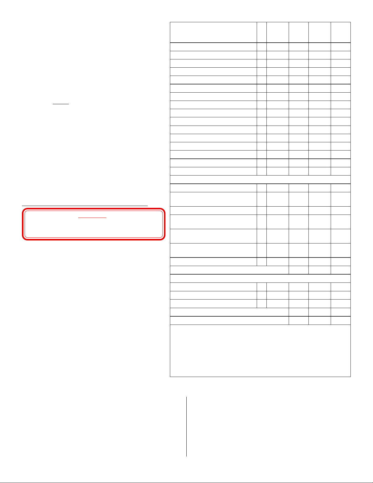
Table 1. Battery versus Standby Current
pukcaByrettaBderiuqeRyrettaBenOseirettaBowT
setuniM51+sruoH4A2.1A9.1
setuniM5+sruoH42A2.0A4.0
Before installation, compute the required standby current for all
accessories powered by the Base Module. The following factors
limit the equipment and devices powered by the Base Module:
• The current drawn by the equipment and devices powered from
the Base Module
• The UL requirement for at least 4 hours plus 15 minutes of
alarm battery life for UL Central Station Burglary, Proprietary
Burglary, Household Burglary, and Household Fire.
• The UL requirement for at least 24 hours (plus 5 minutes of
alarm) battery life for UL Central Station Fire.
3
Page 4
Knowing this, the following rule applies for battery operation:
• The Base Module’s maximum Normal Standby current
cannot exceed the battery(s) Ampere-Hour (AH)
capacity divided by the number of hours of required
battery operation.
Example: two 7 AH batteries installed in a system
requiring 24 hours of backup operation.
7 x 2 = 14 AH
14 AH ÷ 24 Hours required backup = 0.58 Amp
Normal Standby current cannot exceed 0.58 Amps
To properly calculate the Advantage plus system’s battery
capacity you
current required by the system. Calculate a system’s AmpereHour requirements using the following factors:
• the total system standby current load
• hours of required standby operation (24 hours for UL
Central Station Fire, 4 hours for other UL configurations)
• the required duration of alarm signaling (normally 4
minutes for fire, 15 minutes for central station burglary).
NOTE: Consult the Authority Having Jurisdiction (AHJ)
MUST evaluate the Normal Standby and Alarm
before installing any Fire system. Local and/or
state fire ordinances could impose limitations on
the maximum number of smoke detectors
installed in one system.
CABINET AND MODULE INSTALLATION
DO NOT INSTALL ADVANTAGE plus IN
LOCATIONS WHERE TEMPERATURES DROP
BELOW 0°F OR RISE ABOVE 122°F.
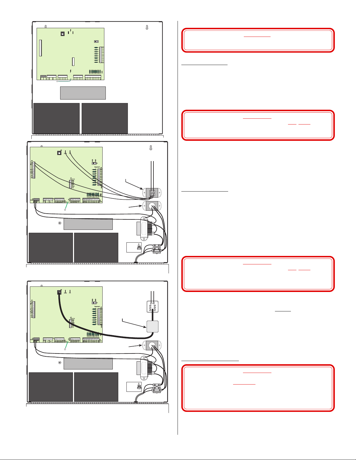
Mount the enclosure next to a standard 120VAC power
source to simplify AC wiring. See Figure 3 and do the
following:
1. Install the six Base Module standoffs by pressing them in
from the back of the cabinet. Also install the standoffs for
any optional modules.
2. Using the cabinet as a guide, mark the top two mounting
hole locations on the mounting surface.
3. Mount the top screws and place the cabinet keyholes on
the screws. Tighten the top screws and secure the cabinet
with the bottom screws.
4. Mount the Base Module on the standoffs installed in step
#1.
5. Mount any additional modules inside the cabinet on the
pop-in standoffs installed in step #1.
CAUTION!
ybdnatS
tnerruC
emaNyrosseccAytQ
latoT
.Am).aE(
mralA
ybdnatS
tnerruC
tnerruC
latoT
mralA
.Am).aE(
tnerruC
eludoMesaB 1051051002002
sulp
DCL
dapyeK52521
DELsulpdapyeK5259-52
eludoMoiduAtramS002002
eludoMnoisnapxE031031
eludoMsulPleT054
eludoMnInetsiL0303
eludoMsseleriW )1etoNees( 051051
rosneSoiduAegatnavdA55
kaerBssalGegatnavdA2162
redaeRdraCelbitapmoCdnageiW
XX0-78303detsiLgnireenignErosneS
XX0-51813detsiLgnireenignErosneS
XX1-51813detsiLgnireenignErosneS
XX1-08813detsiLgnireenignErosneS
X-30513detsiLgnireenignErosneS
4#hguorht1#stuptuOyrailixuA
W4-002SD
W4-DH002SD
)
esaB
W4BM
AW4BM
)yaleRxuA/w
EW4BM
SW4BM
)rednuoSBd58/w
002LOE
)esaBW4-002BM/w002SD(
W4-002BM/wDH002SD(
)daeHeriW-4052SD/wesaB(
esaB/wdaeHeriW-4052SD(
esaB/wdaeHeriW-4052SD(
)noisivrepuSrewoPdnayaleRxuA/w
esaB/wdaeHeriW-4052SD(
)eludoMeniLfodnE(
80.052
80.052
80.084
80.065
80.008
80.036
0303
SLATOT)1(
srotaicnunnAlausiVdnaelbiduA
)2(
SLATOT)3(
.smetsys
tnerruCmralAmretgnolro,tnerruCybdnatSlatoT,rebmunsihT)1( TONNACehtdeecxe
.)1elbaTees(sruohpukcabforebmun
.)spmA5.1(Am005,1otdetimilsitnerruclleBeludoMesaBehT)2(
tnerruClleBdnatnerruCmralAlatoTdenibmoceht,rebmunsihT)3( TONNACdeecxe
.remrofsnart
Figure 2. Advantage plus UL Standby Battery Chart
detacifitreCLUnidesuebtonyamdna,detsiLLUTONsieludoMsseleriWehT:1ETON
emarfnepoehtgnisufiAm006,1ro,remrofsnartdetnuom-gulpehtgnisufiAm009,1
4
Page 5
Base Module
AC AND EARTH GROUND WIRING
CAUTION!
DO NOT CONNECT BASE MODULE JACK J1 UNTIL
ALL TRANSFORMER WIRING IS COMPLETE.
Earth
GND
BatteryBattery
Dedicated
Phone Line
Optional Ditek Data
Loop Protector
(P/N 08061698)
DITEK
DANGER
Fuse
DITEK
WHT
GRN
BLK
Strain Relief
To Dial
Telephone Line
Ditek 120 VAC Surge
Protector (P/N 08061699)
BatteryBattery
115 VAC via either power cord (included)
or from direct supply (enclosed in conduit).
AC Power Wiring
(using plug-mounted transformer)
Run an 18AWG (or larger) 2-conductor cable out the hole in the
cabinet bottom to the plug-mount transformer (or the transformer
enclosure).
The Base Module J1 screw terminal block pins 1 and 2 (labeled AC
16.5V) provides the connections for the 16.5VAC, 50 VA input from
the plug-mount transformer. Connect the power wires into the J1-1
and 2 terminals (polarity is not important).
WARNING!
UNLESS OTHERWISE INSTRUCTED,
DO NOT PLUG
THE TRANSFORMER INTO THE AC OUTLET UNTIL
ALL WIRING IS COMPLETE.
Connect the wires to the transformer terminals.
When ready to plug the transformer into the AC outlet, remove the
outlet cover plate screw and place it through the transformer case tab.
Plug the transformer into the bottom outlet, insert the screw through
the transformer and cover plate, then tighten. This secures the
transformer, preventing accidental disconnection.
AC Power Wiring
(using open frame transformer)
The open frame transformer comes pre-installed inside the chassis
with a fuse block and a DITEK 120 VAC surge protector.
AC power coming inside the chassis connects at the fuse block as
shown in Figure 3. You can bring AC power to the fuse block via
either the AC power cord (included), or wire it directly from a 120
VAC power line.
The Base Module J1 screw terminal block pins 1 and 2 (labeled AC
16.5V) provides the connections for the 16.0VAC, 43 VA input from
the open frame transformer. Connect the power wires from the
transformer to the J1-1 and 2 terminals (polarity is not important).
WARNING!
UNLESS OTHERWISE INSTRUCTED,
DO NOT PLUG
THE TRANSFORMER CORD INTO THE AC OUTLET
OR TURN THE CIRCUIT BREAKER “ON” UNTIL
ALL WIRING IS COMPLETE.
Optional Ditek
Data Protector
(P/N 08060085)
Ditek 120 VAC Surge
Protector (P/N 08061699)
Earth
GND
DANGER
BatteryBattery
115 VAC via either power cord (included)
or from direct supply (enclosed in conduit).
Fuse
Strain Relief
Figure 3. Advantage plus Enclosure Layout
DITEK
3
2
1
WHT
GRN
BLK
5
4
6
7
8
SYSTEM GROUNDING
NOTE: All Advantage plus modules isolate earth ground
from signal ground. This is done to meet UL
requirements, and also allows all the interconnect
modules to share the same signal ground when there
may be a large difference in potential between earth
grounds. Earth ground must remain isolated from
signal ground.
Earth Ground Wiring
WARNING!
IF USING THE 115 VAC, 43 VA OPEN FRAME
TRANSFORMER
EARTH GROUND TO THE CHASSIS EARTH GROUND
STUD. THE ELECTRICAL GROUND AT THE OPEN
FRAME TRANSFORMER ACTS AS THE EARTH
NOTE: Always install AC and Earth Ground wiring per Article
250 of the National Electrical Code.
5
DO NOT CONNECT AN EXTERNAL
GROUND IN THIS CHASSIS.
Page 6

Connect one end of a heavy gauge wire (12 gauge solid recommended) to a known good earth ground. Keep the distance from the
earth ground as short as possible, with no sharp bends.
Strip the other end of the earth ground wire and crimp it into the lug
supplied in the installation kit. Secure the lug, along with the Base
Module Earth Ground lead to the chassis stud located on the left side
of the chassis. Tighten the screw, ensuring all wires make good
connection.
NOTE: Also connect the Earth Ground leads of all other
optional modules installed inside the chassis to the
chassis earth ground stud.
The earth ground provides the modules protection against static
electrical shocks and high power surges. It also provides a convenient earth ground connection for lightning protection.
Bonding Signal Grounds
The signal ground of all interconnected modules must always be
bonded together. Bonding the signal grounds of interconnected
modules greatly reduces communication problems and lightning
damage.
The bonding conductor should follow the data bus (RS-485)
wherever it goes. You can accomplish this using a spare wire inside
an interconnecting cable, the cable’s drain wire, or a shield of the
individually twisted pair, individually shielded RS-485 data cable.
Convenient Base Module signal ground connections can be found at
on J5 pins 1, 19 and 20 labeled “GND” (this is
NOT Earth Ground).
If using a cable’s foil shield for bonding, terminate the shield to a
short length of uninsulated 22 AWG wire before punching down to
an unused GND pin.
NOTE: See each module’s installation instructions for the
appropriate bonding connections.
BASE MODULE PRE-INSTALLATION TEST
WHEN PLUGGING IN THE TRANSFORMER, A SHORT
ON A BASE MODULE 12 VOLT LINE CAN BLOW THE
TRANSFORMER. ALWAYS USE BATTERY POWER
TO PERFORM THE PRE-INSTALLATION TEST.
If the Base Module cannot pass this test, replace it and test the new
unit. Do this test with no telephone or field wiring connections and
only battery power applied.
1. Set the LCD plus keypad’s internal jumper to address #1.
2. Connect the LCD plus keypad ground and power to Base Module
J2 pins 1 and 6 respectively.
3. Connect the LCD keypad DATA+ and DATA- to Base Module
J4 pins 1 and 2 respectively.
4. Place the Base Module TEST/OPER switch (S1) in the TEST
position.
5. Power the panel up by carefully plugging the battery leads to the
backup battery(s). The Black lead connects to the negative
terminals of the 12VDC batteries. Connect the Red lead to the
positive battery terminals.
6. If within 5 seconds a “SETUP MODE” message appears on the
LCD display, the Base Module is probably operational.
7. Power the panel down by carefully unplugging the battery leads
from the backup battery(s).
ADVANTAG
E plus
Throughout these procedures refer to the Installation Diagram shown
in Figure 7.
NOTE: Before installing a UL Certified Fire System read and
understand the requirements in chapter two (residential)
or chapter three (commercial) of NFPA 72, “National
Fire Alarm Code.”
CAUTION!
WIRING
BATTERY WIRING
To supply the minimum required backup power in case of AC power
loss, install the 12VDC, 7AH, sealed lead acid battery(s) inside the
enclosure. For UL Fire installations, use the fused battery leads and
the second 7 AH battery from the ULF Install Kit.
Connect the Black lead to J1 pin 3 (labeled BAT-) and the Red lead
to J1 pin 4 (labeled BAT+) . Connect the Black lead to the negative
terminal of the 12VDC battery(s) and connect the Red lead to the
positive battery(s) terminal.
Observe polarity when making the battery connections. Connecting
the leads backward can overheat the power supply.
WARNING!
UNLESS OTHERWISE INSTRUCTED,
DO NOT
CONNECT THE BATTERY(S) UNTIL ALL
WIRING IS COMPLETE.
BASE MODULE J2 WIRING
“GND” and “+12V” and (J2 Pins 1-4 and 6-9)
Base Module J2 pins 1 through 4 (labeled GND) and J2 pins 6
through 9 (labeled +12V) serve as un-switched +12VDC auxiliary
power connections for optional devices.
These current limited outputs can supply up to 1,600mA of current
for optional devices.
NOTE: UL requires that at least one LCD plus keypad be
powered directly from the Base Module. This LCD
plus keypad can display module down status if modules
lose power.
Bell (J2 Pins 11 and 12)
Base Module J2 pins 11 and 12 (labeled BELL- and + respectively) are the connections for bells, horns or combination horn/
strobes operating on 12 VDC up to 1,500 mA (1.5 Amps). Select the
bell or DC option if a siren has a built-in driver.
Observe polarity when connecting wires.
Table 2 lists audible and visual devices that are compatible with
Advantage plus.
Table 2. Compatible Audible/Visual Devices
kcoleehW
)s(ledoM
2FD-HC,2FC-HC,FB-HCV6.51-0.01Am02--semihC
RFH-21-PSL,RFV21-M1SLV5.61-5.01--Am551ebortS
RFV-21-MPSL,RFV-21-M1SLV5.61-5.01--Am012ebortS
R-21-6G-BMV4.41-6.9Am08--lleB
R-FH-W-21-01G-BMV4.41-6.9Am08Am05ebortS/lleB
RFH-21-PSM,RFV-21-1SMV6.51-5.01--Am722ebortS
R-42/21-4TM,R42/21TMV6.51-5.01Am001--nroH
RFV-SL-4TM,RFV-SL-21-TMV6.51-5.01Am001Am551ebortS/nroH
RFV-MSL-4TM,RFV-MSL-21-TMV6.51-5.01Am001Am012ebortS/nroH
RFV-SM-21-4TM,RFV-SM-21-TMV6.51-5.01Am001Am722ebortS/nroH
W-21-ZIM,R-21-ZIM5.01V6.51-Am8nroHiniM
RFV-SL-21-ZIM5.01V6.51-Am861ebortS/nroH
RFV-MSL-21-ZIM5.01V6.51-Am822ebortS/nroH
RFV-SM-21-ZIM5.01V6.51-Am342ebortS/nroH
RFV-5121-SAV6.51-5.01Am562ebortS/nroH
RFV-575121-SAV6.51-5.01Am953ebortS/nroH
RFV-0321-SAV6.51-5.01Am353ebortS/nroH
R-21-HA6.51-0.9Am49nroH
R-42/21-MS
R-42/21-MSD
gnitarepO
egatloV
5.01
6.51-
5.01
6.51-
rednuoS
ebortS
tnerruC
tnerruCstnemmoC
Am52eludoMcnyS
Am83eludoMcnyS
6
Page 7

BASE MODULE J3 WIRING
AX2
9
s
All Base Module audio inputs are balanced and there are two ways to
use them:
• audio verification sensor inputs
• audio from optional SmartAudio or ListenIn Modules
NOTE: When installing SmartAudio or ListenIn Modules in the
Advantage plus system we strongly recommend that you
not connect AudioSensors to the Base Module audio
inputs.
Audio from SmartAudio and ListenIn Modules is a balanced signal,
requiring
two wires for each audio input and output. If you install
either of the modules you must connect the Base Module AU+ and
AU- inputs to the corresponding outputs from the modules.
Audio Input Wiring
YOU MUST USE SEPARATE TWISTED PAIR,
INDIVIDUALLY SHIELDED CABLES FOR THE
AUDIO AND RS-485 DATA BUSSES. RUNNING DATA
AND AUDIO IN THE SAME CABLE CAN RESULT IN
SERIOUS DATA NOISE IN THE AUDIO SIGNAL.
If not installing SmartAudio Modules or ListenIn modules, you can
connect up to four verification AudioSensors to Base Module jack J3.
Audio verification devices should only be Advantage AudioSensors.
NOTE: Advantage plus is NOT compatible with the older
Advantor PA-15 and GBD-III audio sensors.
General Advantage AudioSensor placement rules are:
1. Mount AudioSensors on solid,
2. The AudioSensor should always face toward the protected area
and away from ambient noise sources.
3. Mount the AudioSensor as close as possible to the area being
protected.
4. Mount AudioSensors high enough to avoid blockage, damage
and tampering, but give more thought to sound factors. The ideal
mounting height is 8 to 10 feet from the floor. Never exceed 13
feet unless special circumstances require such height.
5. Mount AudioSensors at least one foot away from corners.
Power, ground, and audio wiring is identical for all system audio
sensors. We recommend using an audio color code of Black
(ground), Green (audio), and Red (+12VDC). Figure 4 and the
installation diagram shows examples of proper wiring using the
standard (BLK, GRN, RED) color code.
NOTE: For best audio quality, the +AS and -AS terminals on
Base Module jack J3 should be the
AudioSensor power and ground.
101112
BAT
V
- +
BELL
+ -
IMPORTANT!
+12 GND
non-vibrating surfaces.
J2
101112
123456789
-AS
-AS
AU-
AU+
AU-
AU+
AU-
AU+
AU-
only source for
AX
MOD
J4
AU+
123456789
+AS
J3
AUDIO
+AS
+12
AX1-
101112
+12
To save wire you may parallel power (Red) and ground (Black) to
several audio sensors.
Always home run and connect each audio
(Green) wire to the Base Module audio sensor input number designated on the Option Summary Sheet. For best audio quality, install
one AudioSensor at each audio input.
Do not connect a ground wire to a +AS terminal, which is +12VDC.
DAT1 & DAT2 (J4 Pins 1 through 4)
Base Module J4 pins 1 through 4 are the RS-485 communication port
connections. The RS-485 communications port gives Advantage
plus its flexibility and expandability.
The Base Module’s RS-485 communication port can interface and
control the following optional modules and devices:
• any combination of up to 16 LCD plus and LED plus
keypads
• eight alarm loop Expansion Modules
• any combination of up to eight SmartAudio Modules and
ListenIn Modules
• seven Access Modules
Use the following guidelines when running cables for an RS-485
communication link:
• Never exceed 2,000 feet from the Base Module
• Always use 22 AWG, individually twisted pair, individually
shielded cable. (See Note below)
• Always observe the proper polarity when making connections
(e.g., DAT+ to DAT+ and DAT- to DAT-).
• Always verify the proper RS-485 address jumper settings on
each module or device.
• Always use the cable’s drain wire, one of the cable’s spare
wires, or a shield to bond the signal grounds (
grounds) of the interfacing modules.
NOTE: RS-485 cable runs of less than 30 feet should not require
twisted pair, individually shielded cable.
Although RS-485 uses a two-wire differential communication, it is
imperative that the signal grounds of the interfacing modules be
bonded together. This common signal ground provides an overall
reference level, eliminating most RS-485 communications problems.
When running RS-485 cables to several modules or devices you can
use both daisy chain and star configurations (see Figure 5).
UL WARNING:
LCD/LCD plus KEYPADS WITH A BLINKING YELLOW
LED, A BLINKING CURSOR AND BEEPING EVERY 10
SECONDS, INDICATE AN RS-485 COMMUNICATIONS
PROBLEM. THE SYSTEM MAY BE INCAPABLE OF
REPORTING FIRE OR BURGLARY ALARMS.
UL requires that at least one LCD/LCD plus keypad be powered
directly from the Base Module to permit display if other modules lose
power.
NOT earth
+
(Supv.)
ealed
years.
ensor Power Rating:
0 Ohms maximum Line
istance
Module and/or ListenIn Module audio outputs
+
Composite audio from optional SmartAudio
J2
TMP
TMP
TEST
GND
+12V
AUD
J1
AudioSensor
SENS
BLK
BLK
GRN
GRN
RED
RED
Ground
6
5
4
3
2
1
J1
SENS
Earth
TMP
TMP
TEST
GND
+12V
AUD
AudioSensor
Figure 4. Advantage plus Jack J3 Wiring
7
Page 8

1 2 3
ux l ary Output Power
4 5 6
7 8 9
0 #
LCD plus
Keypad
Keypad
LCD
Expansion
ListenIn
Module
* Not UL Listed
Module
Access
Module
LCD plus
Keypad
Access
Module
1 2 3
4 5 6
7 8 9
0 #
ListenIn
Module
Base
Module
SmartAudio
Module
SmartAudio
Module
SmartAudio
Module
Expansion
Module
Access
Module
Figure 5. RS-485 Cable Configurations
Auxiliary Outputs (J4 Pins 5 Through 12)
Base Module J4 pins 16 through 19 (labeled AX1- through AX4and their respective +12 outputs) are the Base Module’s four
Auxiliary Outputs. Each output consists of a +12 volt line and a
switched ground.
The “+12” lines supply the power for external devices. You may
daisy-chain external device power from one “+12” line, but home run
the “AX1-” through “AX4-” lines from the Base Module.
NOTE: If optioned for Enable Line Monitor 2, the AX4 output
is automatically dedicated to the line monitor feature.
The current drawn by existing devices (i.e., sensors and keypads)
determines the current available for auxiliary devices. If the current is
available, each auxiliary output can control up to 100mA.
BASE MODULE J5 WIRING
Alarm Loop Wiring
Base Module jacks J5 and J6 contain the inputs for the Base
Module’s 16 alarm loops (labeled A1 through A16). Each loop
location is labeled on the board to assist in installation.
NOTE: Certificated UL systems use the 1KEOL assembly from
their respective UL Installation Kit.
Fire Alarm Loop Wiring
Table 3 lists smoke detectors and other devices compatible with
Advantage plus Fire systems. When installing 4-wire smoke
detectors you must also install Power Supervision Unit(s). Recommended is the DSI EOL 200 (12VDC), or another UL Listed device
of equivalent ratings.
Install the power supervisory unit at the sensor farthest from the Base
Module on each alarm circuit.
Table 3. Compatible Smoke Detectors and Devices
ledoM/rerutcafunaM
)Am(tnerruC
W4-002SD,smetsySnoitceteD80.052CDV72-01
DH002SD,smetsySnoitceteD80.052CDV72-01
W4BM,smetsySnoitceteD80.084CDV03-01
AW4BM,smetsySnoitceteD80.065CDV03-01
EW4BM,smetsySnoitceteD80.008CDV03-01
SW4BM,smetsySnoitceteD80.036CDV03-01
002LOE,smetsySnoitceteD0303CDV03-01
ybdnatS
mralA
If installing 4-wire smoke detectors, wire the detectors as shown in
Figure 6, wiring detector power to an auxiliary output optioned for
Base
Module
1 2 3
4 5 6
7 8 9
0 #
Wireless
Module*
LCD plus
Keypad
LCD
Keypad
1 2 3
4 5 6
7 8 9
LCD plus
Keypad
“DS or PU Resets Smokes.” This configuration allows a system user
to reset the smoke detectors from a keypad.
9.7-12VDC, 100mA each
X
D
Option the Auxiliary Output for "DS
0 #
or PU Resets Smokes" to allow
detector reset from a keypad.
You must also install
(P/N 1KEOL from the ULF Installation Kit) on each Base Module
alarm loop to provide fire loop supervision. Install the 1KEOL
resistors at the farthest point from the Base Module in each active
alarm loop, in parallel with an alarm-on-short sensor.
INACTIVE alarm loops do not require jumpers. See the Options
Sheet for more information.
To meet UL requirements for annunciation supervision, unique
fire sound, and power limit, the annunciators must be wired as
shown on sheet 2 of Figure 7. The Wheelock MT annunciators
must be set for “Code 3” pattern, or the Wheelock AS or AH
sounders used with Wheelock DSM synchronizers.
NOTE: You must use separate burglary annunciators (if
The relay connects between Bell (+) and the Base Module auxiliary
output optioned with the Independent Zone Bell option.
The Tamper alarm loop supervises the annunciator output, sending a
Tamper alarm if the annunciator circuit is cut or shorted. The Tamper
alarm is ignored if it is received with a FIRE alarm.
Intrusion Alarm Loop Wiring
Power and ground to alarm sensors, detectors or devices requiring
auxiliary power must be run on separate wires from the alarm loop.
Obtain 24-hour power from Base Module board J2 pins labeled
“+12” and “GND” respectively.
To provide the required alarm circuit supervision, you must install
one of the supplied 1KEOL end-of-line resistors in series with alarmon-open contacts (such as door switches), or in parallel with alarmon-closure contacts. Install the 1KEOL resistors at the
initiating device from the Base Module on each of the circuits.
NOTE: The Tamper alarm loop does not require a 1KEOL
)Am(tnerruCegatloV
OPTIONAL CARD READER WIRING
The Base Module can support one access controlled door, but be
aware that the access events cannot be uploaded for report generation. Authorized users can view the last 100 events at an LCD plus
keypad. The Base Module maximum number of card holders is also
restricted to 99 (employees 01-99).
NOTE: The card reader is always assigned to Zone A.
The application uses a Base Module auxiliary output for the door lock
interface, and the Base Module’s existing card reader interface.
+12
101112
AX1-
Rating:
maximum
+12
AX2-
+12
AX3-
+12
DAT2
AX4-
- +
DAT1
- +
123456789
TMP
A15 A14 A13 A12 A11 A10 A9
- +
- +
A15
A16
GND
+5V
CR0
CR1
- +
A14
1011121314151617181920
- +
- +
- +
- +
A13
A12
A11
A10
Figure 6. Wiring 4-Wire Smoke Detectors
one 1K Ohm End-of-Line assembly
present).
resistor if the loop does not extend outside the Base
Module chassis.
123456789
J5
LOOPS
GND
BLK
RED
BLU
BLU
1KEOL
farthest
EOL-200
DS
8
Page 9

Dial Telephone Line
Connection
To House
Telephone
678
5
4
321
To Dial
Telco Line
Dedicated Line
Figure 7. Advantage plus Installation Diagram (Sheet 1 of 2)
Connection
To
Dedicated
Line
678
5
4
321
To Base
Module J8
RJ Jack
9
18AWG, 2-Conductor Cable
(15 feet maximum)
Transformer:
Input-120VAC, .31A
Output-16.5 VAC, 50VA
(Supervised)
WARNING!
DO NOT connect the
transformer to a
receptacle controlled by
a switch!
Battery Charging :
400mA max., 10mA min., 12V, 7AH
Sealed Lead-Acid Batteries,
estimated life 3 years.
NOTE: All UL Fire and Burglary installations
must use the fused RJ31X jack included
in the ULB and ULF Installation Kits.
WARNING!
Detection Systems, DS200-4W (Smoke Detector)
Detection Systems, DS200HD-4W (Smoke Detector)
Detection Systems, MB4W (Smoke Detector)
Detection Systems, MB4WA (Smoke Detector)
Detection Systems, MB4WE (Smoke Detector)
Detection Systems, MB4WS (Smoke Detector)
Detection Systems, EOL200 (End of Line Module)
Wheelock CH-BF, CH-CF2, CH-DF2
Wheelock LS1M-12VFR, LSP-12-HFR
Wheelock LS1M-12-VFR, LSPM-12-VFR
Wheelock MB-G6-12-R
Wheelock MMB-G10-12-W-HFR-R
Wheelock MS1-12-VFR, MSP-12-HFR
Wheelock MT12/24R, MT4-12/24-R
Wheelock MT-12-LS-VFR, MT4-LS-VFR
Wheelock MT-12-LSM-VFR, MT4-LSM-VFR
Wheelock MT-12-MS-VFR, MT4-12-MS-VFR
Wheelock MIZ-12-R, MIZ-12-W
Wheelock MIZ-12-LS-VFR
Wheelock MIZ-12-LSM-VFR
Wheelock MIZ-12-MS-VFR
Wheelock AS-1215-VFR
Wheelock AS-121575-VFR
Wheelock AS-1230-VFR
Wheelock AH-12-R
Wheelock SM-12/24-R and DSM-12/24-R
J9
RING
TIP
DEDT
DEDR
----
----
----
----
----
EGND
----
XF2
DUPO
ANS
TLM
----
----
+12V
----
GND
Electrical shock hazard present
during telephone line servicing.
UL LISTED POWER LIMITED CIRCUITS:
1. J2-11,12 Local Bell
2. A1 through A16 Alarm Loops
3. AX1- through AX4- Auxiliary Outputs
4. J3-1 & 2 and 11 & 12 Audio Sensor connections
5. J1-1 through 4 and J1-6 through 9 Voltage Out
1
COMPATIBLE UL LISTED SENSORS & DEVICES:
2
3
4
5
6
7
8
9
10
11
12
13
14
15
16
17
18
19
20
Bell Power Rating :
9.2-12VDC, 1.5 A maximum
+
BELL
+ -
101112
+12 GND
J1
POWER
(Supv.)
AC
BAT
16.5V
- +
+
(Supv.)
See Sheet 2 for
Supervised Fire
Annunciator Wiring
+
Advantage GlassBreak (GBD-S) Power Rating:
+12VDC, 26mA, 100 Ohms max. Line Resistance
Composite audio from optional SmartAudio
Module and/or ListenIn Module audio outputs
COM
GND
+12V
AUD
NO
NC
SENS
GBD-S
Advantage plus Installation Diagram
11/10/97
Recommended Fire Initiating
TELEPHONE LINE:
J8
RING TIP
NOTE:
UL Certificated Fire systems shall be installed
in accordance with Chapter 2 of the National
Fire Alarm Code, ANSI/NFPA 72-1993.
J7
TEST PTS
1
2
3
4
5
6
7
8
9
10
Voice Grade - 300-3300HZ, 16dB loss (typical)
TERMINATIONS:
Use Panduit tool number MCT-100F for all Panduit
connections.
Use UL Recognized limited energy copper cables for all
terminations.
CAUTION!
Incorrect wiring may result
in damage to the unit!
RESET
AUDIO
------+12V
GSTART
AGND
+5V
+5VSTB
LAUD
-------
Alarm Loop Power Rating :
5V, 5mA, 470 Ohms maximum
line resistance
OPER
Supervised
A1
A2
A3
A4
A5
A6
A7
A8
TEST
S1
J6
GND
1
2
A1
- +
3
4
A2
- +
5
6
A3
- +
7
8
A4
- +
9
10
A5
- +
11
12
A6
- +
13
14
A7
- +
15
16
A8
- +
17
18
A9
- +
19
20
GND
Enclosure
LOOPS
Tamper
Auxiliary Output Power Rating :
123456789
J5
LOOPS
GND
1K
Ohm
N/O Loop
No Connection
GND
9.7-12VDC, 100mA each
maximum
J3
AUDIO
RED
AX
MOD
J4
Earth
Ground
+12
AX1-
101112
+12
AX2-
+12
AX3-
+12
DAT2
AX4-
123456789
DAT1
- +
- +
Reader
LED
J2
101112
123456789
-AS
-AS
AU-
AU+
AU-
J1
BLK
BLK
GRN
AU+
AU-
AU+
AU-
AU+
GRN
123456789
+AS
+AS
RED
Card Reader
TMP
6
AudioSensor
TMP
5
4
J2
TEST
3
GND
2
+12V
1
AUD
J1
SENS
RS-485 data to optional Expansion Modules,
SmartAudio Modules, ListenIn Modules,
Access Modules, Wireless Module* and LCD
plus keypads. (* not UL Listed)
GND
GND
+5V
(optional)
A16
A15 A14 A13 A12 A11 A10 A9
1011121314151617181920
- +
- +
- +
- +
A16
CR0
CR1
A15
A14
A13
N/C Loop
1K
Ohm
- +
A12
- +
A11
- +
A10
Advantage AudioSensor Power Rating:
+12VDC, 5mA, 100 Ohms max. Line Resistance
Loop Connection
(Style B)
DS
EOL-200
RED
BLK
BRN
BRN
1KEOL
Listed
4-Wire Smoke
Detectors
Ground and Power from
Base Module J4 pins 11
and 12 respectively.
Switch
1KEOL
Automatic, Manual,
Sprinkler Supervisory or
Waterflow Devices.
LCD/LCD plus Keypad Power Rating:
9-15VDC, 45mA, 5 Ohms maximum
Line Resistance
(Keypad Must Be Supervised)
1
1248
2
3
4
5
6
ADDRESS
JUMPERS
7
8
9
BEEPOUT
10
GND
11
DATA-
12
DATA+
13
+12VIN
Page 10

BELL
+ -
+12 GND
-AS
-AS
AU-
AU+
AU-
AU+
AU-
AU+
AU-
AU+
+AS
+AS
+12
AX1-
+12
AX2-
+12
AX3-
+12
AX4-
DAT2
- +
DAT1
- +
J2
J3
AUDIO
AX
MOD
J4
- +
A10
GND
GND
+5V
CR0
CR1
- +
A11
- +
A12
- +
A13
- +
A14
- +
A15
- +
A16
A16
J5
LOOPS
A15 A14 A13 A12 A11 A10 A9
123456789
1011121314151617181920
123456789
101112
123456789
101112
123456789
101112
GND
-
Burg
Sounder
(Optional)
+
1 4 7 13
NC N0
NC N0
3 6 9 14
NC N0
2 5 8
- Strobe +
COM
COM
COM
Fire
(Optional)
Figure 7. Advantage plus Installation Diagram (Sheet 2 of 2)
AUX 1 (-)
(Fire Bell)
BELL
SUPERVISION
RELAY
Loop 16 (+)
(Tamper)
-
-
MT
HORN
+
-
MT
HORN
+
AUD
+
AUD
OUT
OUT
-
STROBE
+
STROBE
-
+
-
AS
HORN
+
-
AS
HORN
+
SM
CODE 3 FIRE SOUNDERS
NOTE:
UL Certificated Fire systems shall be installed
in accordance with Chapter 2 of the National
Fire Alarm Code, ANSI/NFPA 72-1993.
Supervised Code 3 Fire Annunciator
1KEOL
Connect the card reader to Base Module J5 pins 16 through 19 using
a 22AWG cable and following the color code shown in the Installation Diagram. Connect the card reader’s LED lead to an available
auxiliary output on J4.
NOTE: See the card reader manufacturer’s installation instruc-
tions for reader connections to the card reader cable.
For optimum performance and reliability, the card reader cable run
should be less than 300 feet from the Base Module.
Option the Base Module for the following:
Required Options:
NOTE: All of the following options are for Module 0 (Base
Module).
Modify-Module-Operation
- Enter a name for the door.
Modify-Module-Door-Equipment
- Enter YES for “Door is Active.”
Modify-Module-Door-Codes
- Enter NO for “Toggle security with Card Read.”
Modify-Module-Door-Lock
- Enter door unlocks for XX seconds. (Traditionally 5 - 10
seconds)
NOTE: You may also have door unlocked during shift or fire and
locked when zone is armed as required.
Examples:
A. Customer requests a storage area door be unlocked from 8 - 5,
with a card swipe required for after hour entry. Use door
“Unlocked during shift” assign a period from 08:00 - 17:00 to
a shift and assign this shift as “Storage room door.”
B. Customer requests the door be unlocked during the day, but
automatically lock at System arming. “Option Door Locks
when armed Y.”
C. A combination of A and B works nicely. Door Unlocked from
8 to 5, however if customer leaves early or arrives late door
remains locked until the zone disarms.
Modify-Opn/Close-Levels
- Assign a valid shift to door #1. Enter the desired Arm/
Disarm Level.
Modify-Module-Door-Alarms
- Enter door is allowed open for XX seconds (traditionally 30
- 120 seconds).
Modify-ASOP-Outputs
- Select “Door Lock Control” for one of the auxiliary outputs.
Select “Card reader LED” for one of the auxiliary outputs.
Modify-ASOP-Loop-Options
- Designate an alarm loop as a special input Free Exit (Loop 2
- 16, #1 is used for door contact).
FIELD DOWNLOADING PROCEDURES
Complete the following steps before downloading options:
1. Load the selected account options from the Account Options
Summary Sheet into the options programmer. (See the “SONICS
Database Management Manual,” P/N 09820426).
2. Ensure all account and employee information is in the SONICS
monitoring console database.
3. If the system contains
to Base Module J8.
NOTE: It is crucial that ALL system (Base Module as well as all
optional modules) options be downloaded
attempting system calibrations or tests.
10
no options, connect the dial telephone line
before
Page 11

NEW ACCOUNT DOWNLOADING
Use one the two following procedure for new equipment (no
previous options) or equipment with failed options:
Base Module Calls Monitoring Station Method
1. Inform the operator you are ready to download and give the
account number.
2. Connect the telephone line and place the Base Module TEST/
OPER switch (S1) in the TEST position.
3. Power the panel up by carefully plugging the transformer into the
AC outlet. The LCD plus keypad displays SETUP MODE.
4. Press the “Download” key.
5. Press the “Call” key.
6. Press the “Enter Options” key.
7. Press the “Enter Phone #” key.
8. If the Base Module uses a dial line, enter the monitoring central
station telephone number and press the “Done” key.
If the Base Module uses a dedicated line, simply press the “Done”
key.
9. Press the “Enter Acct #” key.
10.Enter the appropriate 4-digit account number, then press “ENTER.”
NOTE: If the Base Module communicates over a dedicated line
this 4-digit number is determined by the phone line
connection at the ERAD Speaker Module in the
monitoring central station.
11.Press the “Quit” key.
12.Press the “Dial” key.
13.Place the OPER/TEST switch (S1) in the OPER position.
14.The LCD plus keypad displays a “calling for download”
message while the Base Module connects with the Speaker
Module.
15.The SONICS operator selects “Account-Panel-Program ASOP.”
The programming computer transfers account options to the Base
Module. During the download process the LCD plus keypad
displays “DOWNLOADING ACTIVE.”
16.After completing the Base Module options download the
programming computer sends a “MASTER RESET” command.
The Base Module then recontacts SONICS with an “UP Panel”
alarm.
NOTE: An “Error 06” appears in the monitoring console’s
status area if an error occurs during the download
sequence.
17.After receiving the “UP Panel” alarm, the operator must
download all add-on module options using the “Account-Panel-
Download Module,” command and selecting the “All” option.
The LCD plus keypad displays a “DOWNLOADING ACTIVE,
please wait” message during the second options download.
18.After finishing the optional module options download, the
operator must reset the system to complete the download sequence.
Monitoring Station Calls Base Module Method
Use all of the previous steps, except:
5. Press the LCD plus keypad “Answer” key.
Skip steps 6 through 12.
14.LCD plus keypad displays “ready for download.” The Base
Module will answer the telephone line on the first ring.
Proceed with steps 15 through 18.
LCD KEYPAD SETUP AND TEST MODES
NOTE: Only LCD plus keypad #1 operates before the system is
downloaded.
Place an Advantage plus system with no options into the Test Mode
by powering it up with the TEST/OPER switch (S1) in the TEST
position.
The keypad displays a
“Waiting for Master
Controller” message.
After approximately 15
seconds the keypad
displays the Setup Mode
screen shown in Figure 8,
indicating the system is in
the Test Mode.
Test Download
Figure 8. LCD Setup Mode Screen
SETUP MODE
HHMM ENTER sets time
select function
SETTING SYSTEM TIME
Any time the LCD plus keypad displays the “HHMM ENTER sets
time” prompt you may set or change the system clock. Using
military time format (i.e., HH=Hours, MM=Minutes, 4 pm = 16:00
hours), enter the current time then press ENTER. The keypad triple
beeps showing the system has accepted the change.
LCD
plus
KEYPAD TEST MODE
From the Setup Mode
screen, pressing the Test
button displays the Test
Mode screen shown in
Figure 9. The Test Mode
screen offers the following
system tests:
• Walk Test
• Auxiliary Output Test
• Audio Test
Walk Outputs Audio
Figure 9. System Test Screen
TEST MODE
press * for status
select function
Walk Test
NOTE: Walk Test does not operate until the entire Advantage
From the Test Mode
screen, pressing the Walk
button places the system in
the Walk Test Mode and
displays the WALK TEST
screen shown in Figure 10.
Using Walk Test you can
perform a functional system test by entering Walk Test then walking
around the facility violating alarm loops. Each loop violation and
restoral sounds the local bell for 1 second.
After violating the loops return to the keypad and press ENTER to
exit the Walk Test. The System Test screen in Figure 9 reappears.
You can press the keypad “*” key (system status) to see the Walk
Test results. Pressing “*” displays the TEST RESULT screen shown
in Figure 12.
plus system has been downloaded.
WALK TEST
in progress
push ENTER when done
Figure 10. Walk Test Screen
System Status (*)
From the System Test
screen you can check the
system status at any time by
pressing the keypad “*”
key. Pressing “*” displays
the STATUS screen shown
in Figure 11.
Pressing the Status button displays the system status. Displayed
status messages may include:
• low battery • cut telephone line
• RPU down • preamp down
• memory error • options error
select display
Status Call Loops
Figure 11. Status Screen
11
Page 12

Pressing the Loops or Call
buttons displays the status
of system alarm loops
(open, shorted, normal).
The word “tested” appears
in the display if the loop
was tested during a Walk
Test (see Figures 12 and 13
for examples).
While viewing the Loop
Status screen pressing
Prior displays the previous
alarm, pressing Next
displays the next alarm.
tested
Prior Quit
FIRE tested
(loop description text)
Prior Quit
LOOP STATUS
Loop # 16 shorted
Figure 12. Loop Status Screen
Event 01 TUE 17:53
Figure 13. Loop Status Screen
(after Download & Walk Test)
Pressing Quit returns you
to the Setup Mode screen (Figure 8).
Outputs Test
From the Test Mode screen
(Figure 9), pressing the
Outputs button displays
the OUTPUTS TEST
screen shown in Figure 14.
Pressing “0” selects the
Base Module. Pressing
numbers 1 through 8 selects
an attached Expansion
Module (see Figure 15).
After selecting a module,
pressing the associated
keypad key toggle the
outputs on and off. Press the number key to turn each output on, and
press it a second time to return the output to its original state.
• “1” for Aux Output #1 • “4” for Aux Output #4
• “2” for Aux Output #2 • “5” for the local bell
• “3” for Aux Output #3
Pressing ENTER returns you to the Outputs Test screen (Figure 14).
OUTPUT TEST - SELECT
0 = BASE MODULE
1 - 8 = EXPANSION MODULE
EXIT
Figure 14. Outputs Test Screen
OUTPUT TEST MOD #1
toggle by entering
aux output #
push ENTER when done
Figure 15. Outputs Test Screen
Audio Test
From the Test Mode screen
(Figure 9), pressing the
Audio button displays the
AUDIO TEST screen
shown in Figure 16.
NOTE: SAM appears
Tip
Ring SAM Done
Figure 16. Audio Test Screen
on the Audio
Test screen ONLY if the system was downloaded with
SmartAudio Module options.
In addition to displaying the Audio Test screen, pressing the Audio
button automatically sends a test tone to all audio sensors.
Pressing the SAM button
displays the STORED
AUDIO TEST screen
shown in Figure 17.
Pressing the Select button
displays a select SAM to
enable screen that allows
Select Store Done
Figure 17. Stored Audio Test Screen
you to enable any of the
connected SmartAudio Modules for testing. Selecting a SmartAudio
Module (pressing any of keys 1 though 8) redisplays the STORED
AUDIO TEST screen shown in Figure 17.
AUDIO TEST
select function
STORED AUDIO TEST
select function
With the phone line
disconnected, pressing the
Store button forces the
REPLAY SAM AUDIO
TEST
panel to store the next 5
seconds of audio and
displays the REPLAY SAM
AUDIO TEST screen
shown in Figure 18.
Replay Done
Figure 18. Replay SAM Audio
Test Screen
Pressing the Replay button routes the stored audio to the TIP and
RING test points on the panel. Connecting a handset to these test
points allows you to check the system’s audio storage circuitry and
the quality of the audio that will be sent to the central station.
Pressing the Done button returns you to the previous screen.
Tip Ring Audio Test
From the Audio Test
screen, pressing the Tip
Ring button displays the
TIP/RING AUDIO TEST
screen shown in Figure 19.
Using the Tip/Ring Audio
Test you can route audio to
the TIP and RING test points on the panel. Connecting a handset to
these test points allows you to check the quality of the audio that will
be sent to the central station.
With the phone line disconnected, pressing the On button routes
audio from all system audio sensors to the TIP and RING test points
on the panel.
Pressing the Off button removes the audio from the TIP and RING
test points.
Pressing the Done button returns you to the initial Audio Test screen
(Figure 16).
LCD
plus
KEYPAD DOWNLOAD MODE
From the Setup Mode
screen, pressing the
Download button displays
the Download Mode screen
shown in Figure 20. The
Download Mode screen
offers Answer, Call and
Quit options.
TIP/RING AUDIO TEST
select function
On Off Done
Figure 19. Tip/Ring Audio Test Screen
DOWNLOAD MODE
select function
Answer Call Quit
Figure 20. Download Mode Screen
Answer Mode
Use the Answer Mode when you contact the central station and
request an options download. While in the Answer Mode the panel
seizes the line and answers the phone (goes off-hook) on the first
ring.
From the Download Mode
screen, pressing the
Answer button places the
system in the Answer
Mode and displays the
screen in Figure 21.
The Exit button gives you
the option of exiting Download Mode and returns you to the initial
Setup Mode screen (Figure 8).
While at the Answer Mode screen, switching the Base Module’s
TEST/OPER switch (S1) back to OPERATE prepares the panel for
options downloading.
The keypad screen clears, then a “Waiting for download” message
appears on the bottom display line until the central station computer
contacts the panel. Once the download begins the keypad display
changes to a “receiving download” message.
Switch to operate
Exit
Figure 21. Answer Mode Screen
12
Page 13

Call Mode
Use the Call Mode to initiate the options download from the LCD
plus keypad connected to
the Base Module.
From the Download Mode
screen, pressing the Call
button places the system in
the Call Mode and displays
the Call Mode screen
shown in Figure 22.
NOTE: The Quit button in all Download screens gives you the
option of exiting and returning to the initial Setup Mode
screen (Figure 8).
From the Download Mode
screen, pressing the Enter
Options button displays the
screen shown in Figure 23.
Pressing the Quit button
returns you to the Call
Mode screen (Figure 22).
Use this screen to enter the
information required to
begin the download. This
includes the central station
telephone number. Pressing
the Enter Phone# button
displays the screen shown
in Figure 24.
Enter the phone number you want the panel to call. Pressing the
Delay button anywhere in the phone number inserts a three second
delay before continuing the dialing sequence. The telephone number
appears on the second line of the display as you enter it.
Press Done after entering the phone number.
Pressing the Enter Acct#
button displays the screen
shown in Figure 25 and
allows you to enter the
optioned account number
(see the options sheet). The
account number appears on
the second line of the
display as you enter it.
Pressing the Quit button returns you to the Call Mode screen (Figure
22).
Figure 23. Download Mode Screen
DOWNLOAD MODE
select function
Enter
Options Dial Quit
Figure 22. Call Mode Screen
DOWNLOAD MODE
select function
Enter Enter
Phone# Acct# Quit
DOWNLOAD MODE
Enter phone# to call
Delay Done
Figure 24. Phone# Screen
DOWNLOAD MODE
Enter panel account#
Push ENTER when done
Figure 25. Account# Screen
COMMUNICATION LOSS
The LCD plus keypad senses a loss of RS-485 communication with
the control panel and annunciates the loss. One minute after communication loss the keypad alerts the user by beeping once each 10
seconds, blinking the yellow LED and blinking the cursor.
The beeping continues until the user presses any key, at which time
the beeping stops and displays a “System Down Call for Service”
message. The message remains until communications restore.
SYSTEM TEST PROCEDURES
Before turning the system over to the customer always perform a
complete functional test to ensure the system is operating properly.
Use the test procedures detailed on the previous pages as a general
reference to test each Advantage plus system’s operation.
AUDIO TEST
Perform an operational audio test by arming the system and creating
alarms that trigger listenback audio. If the system contains SmartAudio Modules, use the Advantor Calibrator set to AUDSEN and
TRIP to trigger audio activations.
Have the operator verify receiving the stored audio (if applicable) and
that the listenback audio is distortion free in all areas. Ensure the
impact sounds are clearly distinguishable and that normal level
speech is intelligible.
RS-485 pickup in audio sounds like clicking. Hearing this clicking
indicates improper data and audio bus wiring between modules.
Dial Mode
Use the Dial Mode to force
the Base Module to dial the
central station. From the
Download Mode screen,
pressing the Dial button
places the system in the
Dial Mode and displays the
Dial Mode screen shown in Figure 26.
While at the Dial Mode screen, switching the panel’s TEST/OPER
switch (S1) back to OPERATE prepares the panel to dial for options
downloading.
The keypad screen clears, then a “Calling for download” message
appears on the bottom keypad display line. Once the download
begins the keypad display changes to a “receiving download”
message.
After completing the download the keypad display automatically
returns to the main screen shown in Figure 8.
Switch to operate
Exit
Figure 26. Dial Mode Screen
13
Page 14

FCC REGULATIONS
This equipment has been tested and found to comply with the limits
set for a Class B digital device, pursuant to Part 15 of the FCC Rules.
These limits are designed to provide reasonable protection against
harmful interferences in a residential installation.
This equipment generates, uses and can radiate radio frequency
energy and, if not installed and used in accordance with the instructions, may cause harmful interference to radio communications.
However, there is no guarantee that interference will not occur in a
particular installation.
If the equipment does cause harmful interference with radio or
television reception, which can be determined by turning the
equipment off and on, the user is encouraged to try and correct the
interference by one or more of the following measures:
• Reorient the receiving antenna
• Increase the separation between the equipment and receiver
• Connect the equipment into an outlet on a circuit different
from that of the receiver
• Consult the dealer or an experienced radio/TV technician for
help
The user may find the following booklet prepared by the Federal
Communications Commission helpful: “How to Identify and Resolve
Radio-TV Interference Problems.” This booklet is available from the
U.S. Government Printing Office, Washington DC 20402, Stock No.
004000003454.
FCC TELEPHONE REQUIREMENTS
This equipment complies with Part 68 of the FCC Rules. Included
with the system is a label that must be affixed on the lower right
outside of the cabinet. The label contains, among other information,
the equipment’s FCC Registration Number (2J8USA-23510-AL-E)
and the Ringer Equivalence Number (REN, 0.3B). This information
must be provided to the telephone company upon request.
The REN determines the number of devices that can connect to a
telephone line and still have all devices ring when called. In most
areas the sum of the REN’s of all devices on one line should not
exceed five (5.0). To be certain of the number of devices that may be
connected to a line, as determined by the REN, contact the local
telephone company for the maximum REN for the calling area.
If this equipment harms the telephone network, the Telephone
Company may temporarily discontinue service. If possible, they will
notify the customer in advance. When advance notice is not practical,
the customer is notified as soon as possible and informed of his right
to file a complaint with the FCC. The telephone company may ask
that you disconnect the equipment until you correct the problem or
until you are sure that the equipment is not malfunctioning.
The telephone company may make changes in its facilities, equipment, operations, or procedures that could affect the proper functioning of this equipment. If they do, the customer is notified in advance
to provide them the opportunity to maintain uninterrupted telephone
service.
This equipment may not be used on coin service provided by the
telephone company. Connection to party lines is subject to state
tariffs.
When installing the Advantage plus alarm dialing system, call your
local telephone company and give them the following information:
1. The telephone number of the line the Advantage plus alarm
dialing system will be attached.
2. The FCC Registration number of the Advantage plus alarm dialing
system.
3. The Advantage plus alarm dialing system Ringer Equivalence
Number (REN), which is 0.3B.
The Base Module connects to the telephone line via a standard USOC
RJ31X jack (supplied). If this type of jack is not available where
installing the Base Module you will need to order it from the telephone company.
CANADIAN IC EQUIPMENT WARNING
To ensure that certified equipment is attached correctly and only to
the networks of participating carriers, Industry Canada (IC) requires
the following written statement:
NOTICE: The Industry Canada label identifies certificated
“
equipment. This certification means that the equipment meets certain
telecommunications network protective, operational, and safety
requirements. IC does not guarantee the equipment will operate to the
user’s satisfaction.
Before installing this equipment, user’s should ensure that it is
permissible to connect to the facilities of the local telecommunications
company. Users must also install the equipment using an acceptable
method of connection.
In some cases, the company’s inside wiring associated with a single
line individual service may be extended by means of a certified
connector assembly (telephone extension cord). The customer should
be aware that compliance with the above conditions may not prevent
degradation of service in some situations.
Repairs to certified equipment should be made by an authorized
Canadian maintenance facility designated by the supplier. Any repairs
or alterations made by the user to this equipment; or equipment
malfunctions, may give the telecommunications company cause to
request the user to disconnect the equipment.
User’s should ensure for their own protection that the electrical ground
connections of the power utility, telephone lines and internal metallic
water pipe system, if present, are connected together. This precaution
may be particularly important in rural areas.”
USERS SHOULD NOT ATTEMPT TO MAKE SUCH
CONNECTIONS THEMSELVES, BUT SHOULD CONTACT
THE APPROPRIATE ELECTRIC INSPECTION
AUTHORITY, OR ELECTRICIAN, AS APPROPRIATE.
The Load Number (LN) assigned to each terminal device denotes the
percentage of the total load to be connected to a telephone loop which is
used by the device, to prevent overloading. The termination on a loop
may be any combination of devices subject only to the requirement that
the total of the Load Numbers of all the devices does not exceed 100.
The Load Number for this product is 4.
CAUTION!
ADVANTOR CORPORATION HARDWARE LIMITED WARRANTY STATEMENT
Advantor Corporation warrants each new product of its manufacture, to be free from defects in material and workmanship.
It will repair or replace defective parts for a period of 24 months from the date of manufacture, providing the equipment
has not been subjected to abnormal conditions such as misuse, abuse, misapplication, alteration, lightning damage or
damage by an Act of God. This excludes packing, handling and shipping charges from the Customer. The limited warranty
is restricted to the original purchaser.
ALL OTHER WARRANTIES, EXPRESSED OR IMPLIED, INCLUDING MERCHANTABILITY, THE
FITNESS OF EQUIPMENT FOR A PARTICULAR PURPOSE OR WITH RESPECT TO CLAIMS OF ANY
THIRD PARTY BY THE WAY OF INFRINGEMENT OR THE LIKE, ARE EXCLUDED.
14
 Loading...