

Page 1
Electronic Counters
10 mHz to 18 GHz/27 GHz
R5372/5373
■ Wide Selection
■ Digital TRAHET Technique
■ Wide FM Allowable Range
■ Digital Comparator Function and Wide Range of Built-In
Calculation Functions
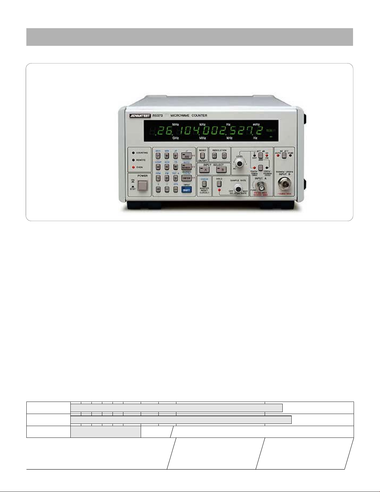
R5372/5373
Microwave Frequency Counters
Recent research in communications and broadcast systems
using microwaves in applications such as broadcast satellites,
telephone circuits and the new field of submillimeter microwave and millimeter-wave communications systems have resulted in dramatic development in components and practical
product designs. This research and development work requires highly accurate frequency measurements. Previous
approaches to measure frequencies in these bands involved the
use of frequency converters or converting oscillators. These
methods, however, were difficult to use as it required troublesome tuning and calculations to determine the actual frequency.
T o solve these problems, ADVANTEST has employed a digital
TRAHET technique to achieve 1 Hz resolution with a gate time
of just one second. It enables not only frequency measurement
but the application of offset to frequency results and calculation of standard deviation, ppm, maximum values, minimum
values and other useful parameters. In addition, a digital
comparator has been provided and totalizing and measurements of the carrier frequency of pulse-modulated signals are
also possible.
(Photo is R5373)
■ Measurements up to the Microwave and Millimeter-
wave Bands
Measurement ranges extend from 10 mHz to 18 GHz for the
R5372 and 10 mHz to 27 GHz for the R5373. It enables a single
counter to be used for broadcast satellite, satellite communications, pilot-signal measurements for radio equipment and
many more diverse applications.
■ Reciprocal Counting Technique for High-Resolution
Measurements
The 10 mHz to 10 MHz mode for the A input uses a reciprocal
technique that calculates the frequency from the period of the
input signal, thereby achieving high resolution in a short
counting time. This enables high-resolution measurements of
the pulse width of pulse-modulated signals and of pulse
repetition frequencies. Making a measurement is as simple as
setting the required measurement resolution; the rest is automatic with extremely easy selection of number of displayed
digits, counting time and frequency.
Selection Guide
10mHz 1Hz 1MHz 1GHz 10GHz 100GHz
R5372
R5373
Measurement method
Major applications
174
10 mHz to 18 GHz
10 mHz to 27 GHz
Reciprocal Direct Counting Digital TRAHET
FM broadcasts
and VHF/UHF
broadcasts
SHF Broadcasts
Microwave circuits
Broadcast satellite
(BS)
Submillimeter-
wave circuits
Communications
50 GHz commercial
satellites (CS)
radio services
Page 2
Electronic Counters
Ideal For Frequency Measurements Over a Wide Band Range
R5372/5373
■ Digital TRAHET T echnique for Microwave Frequency
Measurements
The digital TRAHET technique combines the advantages of
the transfer technique which provides relatively high-sensitivity measurements and the heterodyne technique which
provides high resolution. Implementing these under microprocessor control, a dramatic improvement in cost performance can be achieved. The frequency ranges covered are 500
MHz to 18 GHz (R5372), 500 MHz to 27 GHz (R5373). After
heterodyning using the digital TRAHET technique, direct
counting is used to provide 1 Hz resolu-tion in just 1 second.
■ Wide Allowable FM Range
Almost all microwave carrier signals are FM modulated by
noise and parasitic FM, demanding from a counter the
ability to tolerate a wide range of FM. In manual measurements, for a signal of 1.4 GHz or greater, these counters can
tolerate ±125 MHz or more. In the range 500 MHz to 1.4
GHz, they can tolerate up to ±25 MHz. For automatic
measurements, the tolerance for FM is 10 MHz
p-p in the worst case.
■ Calculation Functions and Digital Comparator
Provided as Standard
The R5372/5373 feature a built-in microprocessor which is
used not only to control the measurement system but to
simplify operations and perform calculations on measurement results as well.
Using these calculation functions, a moving difference display, scaling, 8–by–8 digit arithmetic operations and displays
of calculated measured values of A/B inputs and B/C inputs
are possible. These features greatly enhance versatility.
Key setting Description
MAX Maximum-value hold
MIN Minimum-value hold
∆ F Deviation (Defined as the difference between maximum and minimum values)
COMP Digital Comparator (GO/NO-GO test)
AVG Averaging (101 to 104 samples)
δ Standard deviation
ACQ Acquisition mode
TR TR4110 Series marker frequency measurement
MANL Manual acquisition mode
PPM Parts per million
TOT A A input totalize
CLR-KB Clear keyboard
x, ÷, OFS Arithmetic operation display
■ FM Deviation Measurements Are Simple
FPU and STL testing of TV relay equipment require measurements of transmitting output and frequencies as well as FM
deviation measurements. The ∆F mode can be used to perform
easy deviation measurements of FM modulated frequencies.
Measurement by means of an external trigger signal is also
possible.
■ Relay Station (STL or FPU) FM Deviation
Measurements
The R5372/5373 have a wide range of calculation functions
which greatly simplify FM deviation measurements. By using an
external signal to open a gate in sync, the ∆F mode is selected.
After this, the delay knob can be turned to perform automatic
internal calculation of the maximum and minimum values after
measurements are started. By using an external start signal (1 µs
min.) synced to an arbitrary amplitude point on a modulated
signal, it is possible to determine the frequency variation with
respect to amplitude of an FM-modulated (or other) signal.
■ Radio Equipment Frequency Measurements Using an
IF Offset Display
The R5372/5373 have an IF offset display function which can be
used to directly display the received frequency of a radio receiver. Simply input the IF fr equency of the heterodyne receiver
as an offset frequency from the keyboard and measure the local
oscillator frequency to directly display the received frequency.
The offset value can be set at any digit down to 0.1 Hz resolution
when setting in MHz units. For local oscillator frequencies
higher than the received frequency , the offset is simply input as
a negative value.
X
F
IF;30MHz
RECEIVER
F
L
R5372/5373
FX=FL+IF
■ High-Accuracy Frequency Measurements on Radio
Receivers
F
X
RECEIVER
FL
Local Frequency
IF
R5372/5373
FX=FL+IF
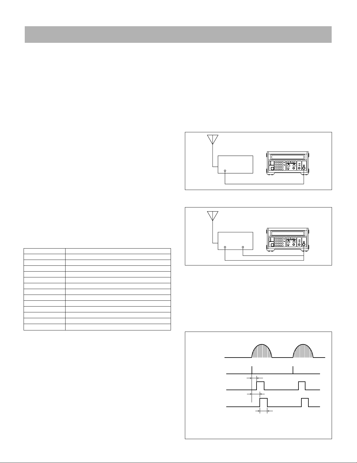
■ Measurement of Oscillating Frequencies In
Magnetrons For Microwave Ovens
Since magnetrons in microwave ovens usually employ intermittent oscillations synched to the power frequency , measurement
with conventional frequency counters has been extremely difficult. The R5372/5373 have a power sync mode to provide
accurate synchronization without external apparatus for measuring oscillating frequencies. By adjusting the delay knob, the
profile of the oscillating frequencies can also be measured.
Magnetron
Oscillating output
LINE sync signal
(Internal)
GATE OUT
Td : Delay
TG : Gate time
Measurement of oscillating frequencies in magnetrons
Td
Td
TG
175
Page 3

Electronic Counters
10 mHz to 18 GHz/27 GHz
R5372/5373 (Continued From Previous Page)
Input Input A Input B
Specifications
Frequency measurement 10 mHz to 10 MHz (DC coupling), 500 MHz to 18 GHz (R5372)
range 10 Hz to 10 MHz (AC coupling), 500 MHz to 27 GHz (R5373)
Input impedance Approx. 1 MΩ/60 pF max. Approx. 50 Ω Approx. 50 Ω
Input sensitivity 25 mVrms 25 mVrms
Input attenuator 0 dB, 20 dB ANS AUTO, 20 dB
Maximum measurement
input
Damage level input 10 Vrms (400 Hz to 1 MHz) 6 Vrms
Coupling DC and AC AC AC
Trigger level ––
Resolution / counting time See Fig. 10 MHz/0.1 µs to 0.1 Hz/10 s switched in decade steps
Measurement accuracy ±1 count ± time base accuracy
Measurement methodReciprocal method Direct counting method
Input connector BNC
*1 Trigger error: ±0.3% with respect to sinewave input of 40 dB or higher S/N
500 mVrms/ATT.0 dB 500 mVrms/ANS OFF 0 dBm/ATT.AUTO
5 Vrms/ATT.20 dB 5 Vrms/ANS ON +10 dBm/ATT. 20 dB
6 Vrms (1 MHz to 10 MHz)
100 Vrms (DC to 400 Hz)
Approx. –1 V to 1V continuously variable
(–10 V to +10 V with ATT at 20 dB)
±(Trigger error*1/measurement period)±1 count ± time
base accuracy (See Fig. for measurement period)
Pulse Modulated Carrier Frequency Measurement
(in manual mode)
Frequency range:
100 MHz to 550 MHz (INPUT A)
500 MHz to 18 GHz (INPUT B, R5372)
500 MHz to 27 GHz (INPUT B, R5373)
Pulse width: Minimum 0.5 µs
Pulse repetition frequency (fR): 10 Hz to 5 MHz
10 MHz to 550 MHz
+10 dBm/ATT. AUTO
+20 dBm/ATT.20 dB
+10 dBm/ATT.AUTO
+20 dBm/ATT.20 dB
±1 count ± time base accuracy ± residual stability
(Residual stability: 1/10 x Measurement frequency (GHz) counts rms)
Heterodyne conversion followed by direct counting using a digital
SMA-type (with N type adaptor) (R5373)
TRAHET technique
N-type (R5372)
Time Base
Time Base Stability:
Standard Option 21 Option 22 Option 23
Aging rate
Long-term stability 1 × 10⁻⁷/yr 8 × 10⁻⁷/yr 5 × 10⁻⁸/yr 2 × 10⁻⁸/yr
Temperature stability (+25°C ± 25°C)
2 × 10⁻⁸/day 5 × 10⁻⁹/day 2 × 10⁻⁹/day 5 × 10
8 × 10⁻⁸/mo 5 × 10⁻⁸/mo 2 × 10⁻⁸/mo 1 × 10⁻⁸/mo
± 5 × 10
-8
± 5 × 10
-8
± 1 × 10
-8
-10
± 5 × 10
/day
-9
Resolution: Set in decades from 0.1 Hz to 10 MHz (1/gate time).
Note however that the setting for resolution (gate time) must
exceed the width of the pulse modulated wave being measured by
at least 0.4 µs.
Accuracy: ±1 count ± time base accuracy
Units: Hz, kHz, MHz, GHz
Totalize: (Input A: 10 mHz to 10 MHz band)
Counting range: DC to 10 MHz
Counting capacity: 0 to 9,999,999,999
10010110210310410510610710
100
33
10
3.3
1
0.33
Measurement time (s)
0.1
0.033
0.01
10m 0.1 1 10 100 1k 10k 100k 1M 10M
Input frequency (Hz)
Maximum resolution: MSD 1 to 2: 9-digit display
MSD 3 to 9: 8-digit display
(resolution up to 0.1 mHz)
30 300 3k 30k 300k 3M
8
(Resolution)
(10mHz)(1mHz)(0.1mHz)
(0.1Hz)
(1Hz)
(10Hz)
(100Hz)
Time base output: Frequency 10 MHz, voltage 1 Vp-p (min.) output
impedance approx. 50 Ω, BNC connector
External Frequency Standard Input: 1 MHz, 2 MHz, 2.5 MHz, 5
MHz and 10 MHz
Voltage 1 to 10 Vp-p
Input impedance Approx. 500 Ω, BNC connector
Calculation Functions
•Digital comparator (with respect to keyed-in upper and lower
limits)
•Maximum value hold, minimum value hold
•Deviation measurement (maximum – minimum)
•Standard deviation
•Averaging
•PPM
•Offset display, drift display
•Scaling display
•Sum and difference display by automatic measurement of inputs
A and B
•Harmonic frequency display
•Arithmetic operations
Fig. 1 Measurement Time, Resolution and Number of Periods
With Respect To Input Frequency
176
Page 4

Electronic Counters
Microwave Counters With Built–In Calculation Functions
R5372/5373
General Specifications
Measurement modes (Inputs B and C):
AUTO 300 ms (Input B) and 1 s max. (Input C) Capture time (from
reset to beginning of counting)
Allowable FM index 10 MHzp-p min.
MANUAL Fixed frequency base set by keyed input, no required
capture time.
Bandwidth (allowable FM) at 0.5 GHz to 1.4 GHz and ±25 MHz
min.
Synchronous trigger modes:
INT Internal triggering with the gate opening and closing in sync
with the pulse modulated input signal.
EXT. START An externally applied start signal is used to open the
gate. (The gate can only be opened when the internal detector
output is on.) The start input signal is a 1.5 V ± (2 to 10) Vp-p
pulse with 1 µs min. (sinewave also usable).
EXT. GATE An external applied start signal is used to open and
close the gate.
LINE The gate is opened in sync with the power line frequency.
(The gate can only be opened when the internal detector
output is on.)
Sampling rate: 50 ms to 5 s continuously variable and HOLD
Delay time: 25 µs to 30 ms, continuously variable and OFF (delay
from INT./EXT./LINE trigger until the start of counting).
Memory backup: Panel setting conditions are held as long as the
AC line is feeding power. Contents of this memory are held for
approximately 2 weeks by an internal Ni-Cd battery even without
connecting the power cable. Full charging of this battery requires
2 to 3 days.
Display: 7-segment green LEDs, 12-digit memory display with fixed
decimal point, character height approx. 11 mm
Operating environment:
Temperature 0 to +40°C
Humidity 85% RH max.
Storage temperature: –20 to +60°C
Option No. Standard Opt. 32 Opt. 42 Opt. 44
Line voltage 90 V to 110 V 103 V to 132 C 198 V to 242 V 207 V to 250 V
48 Hz to 66 Hz
Power requirements: Specified at time of ordering
Power consumption: 90 VA max. (R5372/5373)
Outer dimensions:
Approx. 255 (W) × 132 (H) × 420 (D) mm (R5372/5373)
Mass: 10 kg max.
Input/Output Functions
R5372 R5373
GPIB interface Option 01 Option 01
BCD data output Option 02 Option 02
*Either Option 01 or option 02 can be selected (not both).
*These options may be added after delivery of the unit by factory retrofitting.
GPIB interface:
Standard 488-1978
Function Output of displayed data and remote control of all front
panel functions.
AUX INPUT/OUTPUT:
Gate signal output, detector output, external reset signal input,
measurement complete signal output.
Input/output level TTL
Connector 14-pin (Amphenol type 57-40140 equiv.)
D-A converted analog output (from AUX INPUT/OUTPUT
connector):
No. of converted digits: Any 3 display digits
Output voltage: –4.995 V to +4.995 V ± 20 mV/+23°C ± 5°C
Output impedance: 100 Ω max.
Digital comparator output (from AUX INPUT/OUTPUT connector):
Level TTL negative logic, open collector output
Standard Accessories
Item Model Product code Remarks
Power cable A01402 Angle type
Input cable A01036-1500 BNC-BNC
Input cable MI-04 N-N
Input cable A01002 SMA-SMA
Accessories (Sold separately)
For R5372/5373
R16058 Transit Case
A02448 Rack Mount Set (EIA)
A02248 Rack Mount Set (JIS)
177
 Loading...