

Page 1
LoRaWAN Node BB-WSW Series
Industrial LoRaWAN Node
Certication
CE
This product has passed the CE test for
environmental specications. Test conditions for
passing included the equipment being operated
within an industrial enclosure. In order to protect
the product from being damaged by ESD
(Electrostatic Discharge) and EMI leakage, we
strongly recommend the use of CE-compliant
industrial enclosure products.
FCC Class A
Note: This equipment has been tested and
found to comply with the limits for a Class
A digital device, pursuant to part 15 of the
FCC Rules. These limits are designed to
provide reasonable protection against harmful
interference when the equipment is operated
in a commercial environment. This equipment
generates, uses, and can radiate radio
frequency energy and, if not installed and used
in accordance with the instruction manual,
may cause harmful interference to radio
communications. Operation of this equipment
in a residential area is likely to cause harmful
interference in which case the user will be
required to correct the interference at his own
expense.
This device complies with Part 15 of the FCC
Rules. Operation is subject to the following two
conditions:
(1) This device may not cause harmful
interference, and
(2) this device must accept any interference
received, including interference that may cause
undesired operation.
Caution: Any changes or modications not
expressly approved by the party responsible for
compliance could void the user’s authority to
operate this equipment. This transmitter must
not be co-located or operating in conjunction
with any other antenna or transmitter.
This equipment complies with FCC radiation
exposure limits set forth for an uncontrolled
environment. This equipment should be installed
and operated with minimum distance 20 cm
between the radiator & your body.
Package List
• 1 x Industrial LoRaWAN node
• 1 x Antenna
• 1 x Cable (BB-WSW2C42 with 2 x cable)
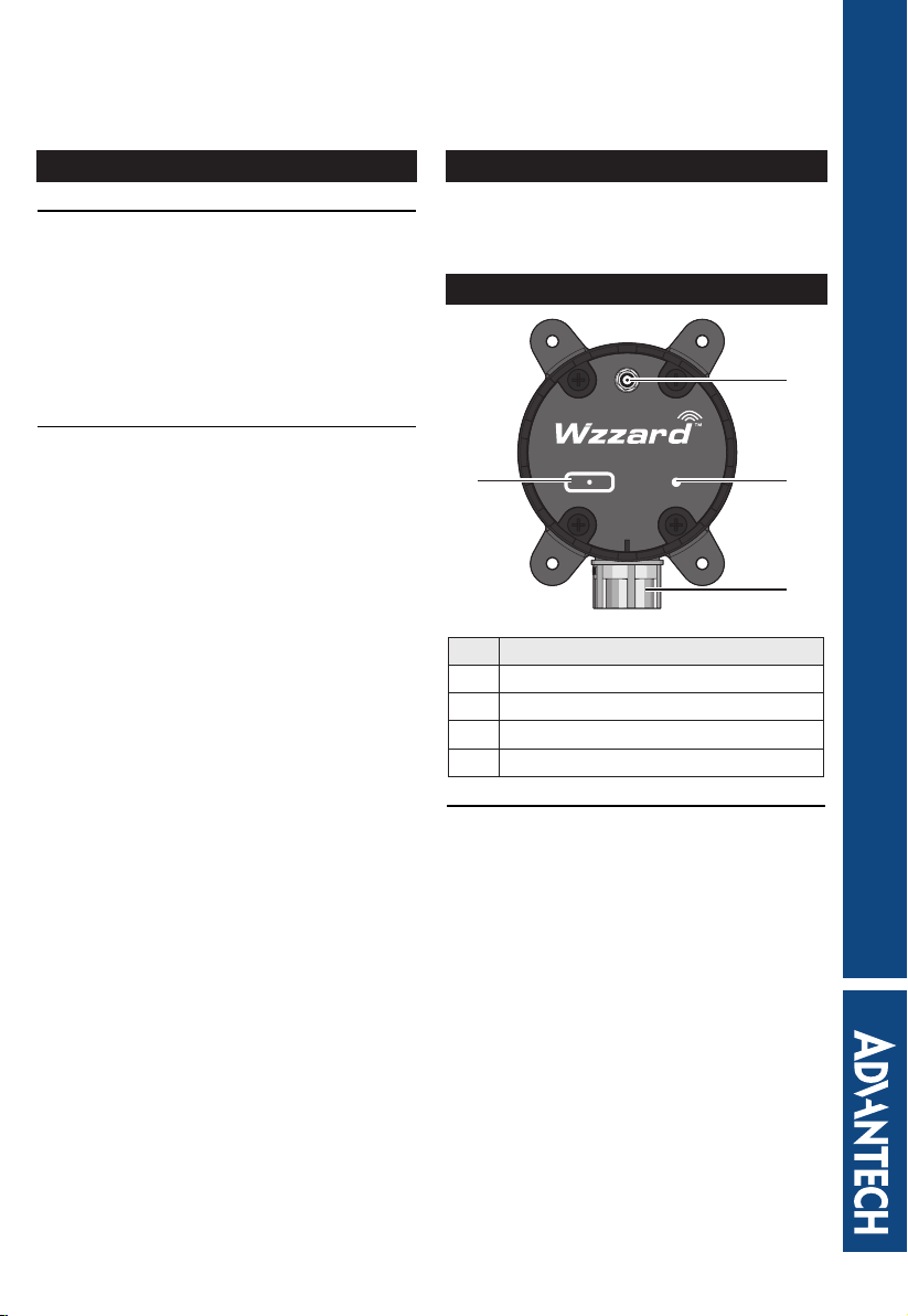
Overview
1
Intelligent Edge Node - Wireless LoRa
4
No Item
1 Antenna slot
2 Status LED
3 Cable conduit
4 Status/Sleep/Reset button
Buttons and LED
The device includes a multifunction button. The
various functions are described as follows:
• To display the status function, press the
button for less than 3 seconds.
■ If LED blinks in 3 second intervals, the
device is in sleep mode.
■ If LED lights solid in 3 second intervals,
the device is in operations mode.
• To change modes from sleep to operation,
press the button between 5 and 15
seconds.
• To reset to factory default settings, press
the button for more than 15 seconds.
advantech-bb.com
Status/Sleep/Reset
Status
2
3
Startup Guide
Page 2

Conguring the LoRaWAN
It is recommended to congure the LoRaWAN
before installing in a permanent location.
The following procedure is written for a
Windows operating system.
1. Locate the screws securing the device cap
and remove them.
2. Remove the cap to expose the internal
connectors.
3. A type A male to micro B USB cable is
required for the following step. Connect
the micro USB connector to the slot on the
device.
4. Power up the target computer and allow it
to boot up completely.
5. Connect the remaining end to a USB slot
on a computer.
6. Once the device and computer are
connected, the computer detects the
USB connection and a virtual COM port is
created.
In the event that the USB connection is
not detected by the operating system, use
the following instructions to download and
install the required driver:
■ Open a browser and navigate to the
following website: https://www.silabs.
com/products/interface/usb-bridges/
classic-usb-bridges/device.cp2104.
■ For Windows 7/8 operating systems,
download the CP210x_Windows_
Driver.
■ For Windows 10 operating systems,
download the CP210x_Universal_
Windows_Driver
■ After downloading, install the driver on
the computer.
NOTE: you may be required to obtain
administrator privilege to install.
7. Open the operating system’s Device
Manager. Go to Start > Control Panel >
Device Manager and select COM & LPT
port entry.
8. Click the drop-down menu to select the
installed COM port and click Apply.
The LoRa Wzzard Utility displays as shown
in the following gure.
For further information about the LoRa
Wzzard Utility, refer to “Starting the
LoRaWAN Node Utility”.
Once the device is congured, it can be
disconnected from the computer to prepare
it for installation on the selected site. After
the device is installed and connected to
respective sensor, the LoRa Wzzard Utility
is then used to customize system, device,
and radio settings and connect it to the
Internet/network.
9. Disconnect the USB cable from the slot on
the device.
10. Replace the cap on the device and secure
it with the screws if it is necessary at this
time.
See “Hardware Installation” to continue.
Page 3
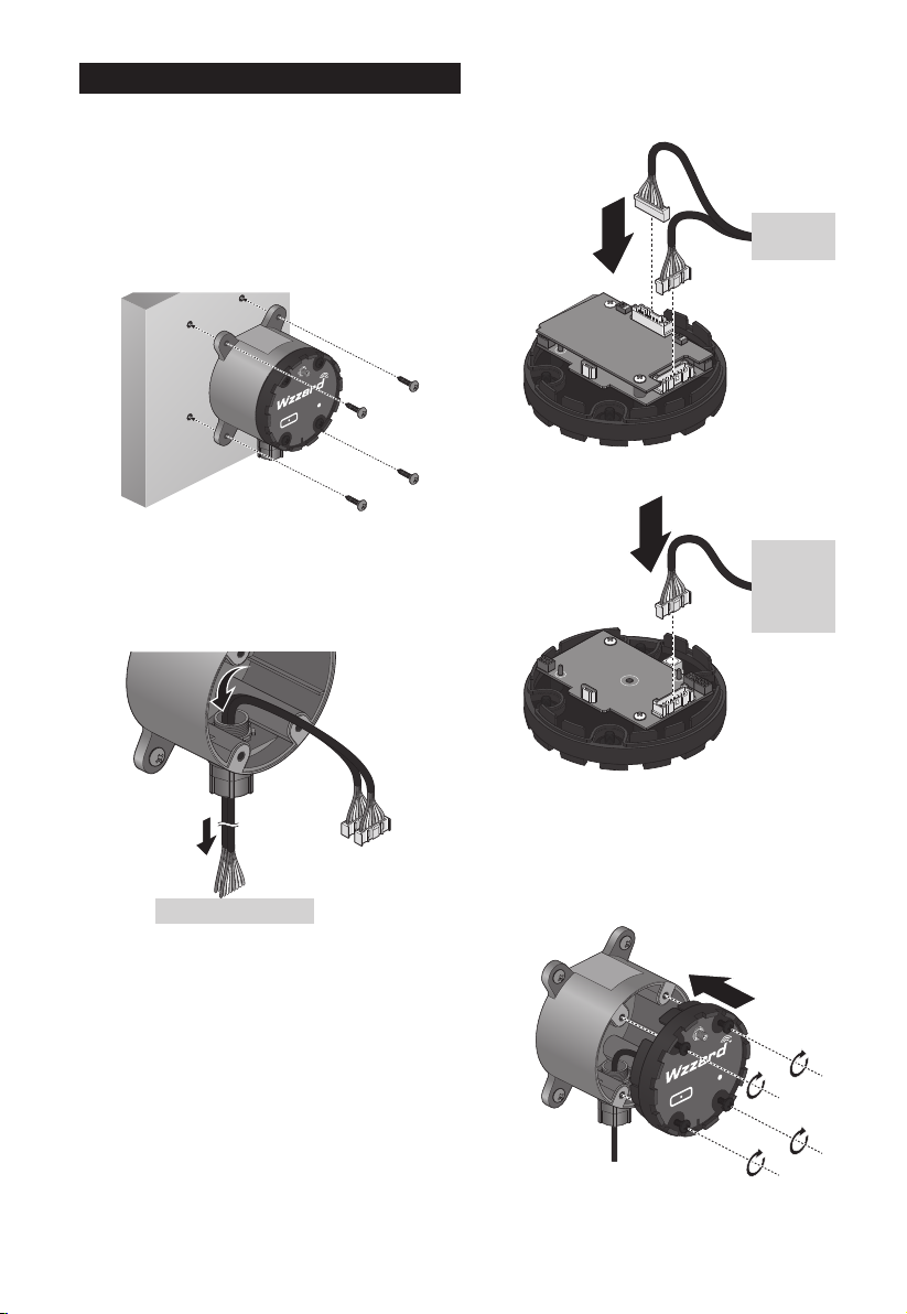
Hardware Installation
Step one, wall mounting:
1. Locate the area to install and mark the
four screw locations. If necessary, drill pilot
holes.
If installing in concrete, it is recommended
to use wall sinks.
2. Align the LoRaWAN to the holes on the
location and secure with the screws.
advantech-bb.com
Status
Intelligent Edge Node - Wirele ss Lo Ra
Status/Sleep/Reset
4. Connect the sensor cables to the
connectors on the device.
■ Node with AI/DI/DO
Connector 1
Connect
to sensor
Connector 2
■ Node with RS485
Step two, routing data cables:
3. Insert the sensor cable through the channel
on the device.
NOTE: Position the cable connector so that
it can be connected to the board.
Connect to sensor
Connect
to power
and
sensor
5. Align the top cover with the base and install
while gently pulling the data cable slack.
If there is resistance when pulling, do not
pull the cable further to avoid damaging the
connector.
6. Secure the top cover with the screws.
advantech-bb.com
Status
Intelligent Edge Node - Wire less L oR a
Status/Sleep/Reset
Page 4

Step three, installing the antenna:
7. Connect the antenna by rotating the
antenna connector in a clockwise direction.
advantech-bb.com
Status
Intelligent Edge Node - Wirel ess Lo Ra
Status/Sleep/Reset
NOTE: Positioning of antenna is crucial for
effective wireless connectivity.
PIN Denition
The following pin denitions are for the cables
supported by the listed LoRaWAN devices:
• Node with AI/DI/DO
■ BB-WSW2C42100-1 (915 MHz)
■ BB-WSW2C42100-2 (868 MHz)
■ BB-WSW2C42100-3 (923 MHz)
PIN Color
Connector 1 Connector 2
Denition Denition
1 Grey AI1 PWR
2 White GND V-
3 Blue AI2 DI1
4 Green GND GND
5 Yellow AI3 DI2
6 Pink GND GND
7 Red AI4 DO
8 Brown GND GND
• Node with RS485
■ BB-WSW2C00015-1 (915 MHz)
■ BB-WSW2C00015-2 (868 MHz)
■ BB-WSW2C00015-3 (923 MHz)
PIN Color Denition
1 Grey PWR
2 White V-
3 Blue NC
4 Green NC
5 Yellow NC
6 Pink NC
7 Red D+
8 Brown D-
Page 5
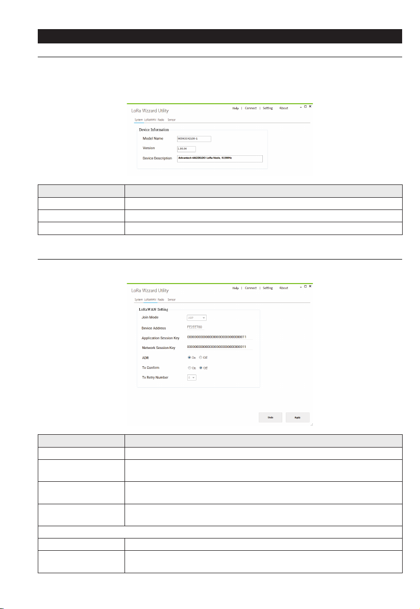
Starting the LoRaWAN Node Utility
System Page
The System page displays the BB-WSW node information.
Right click on the System page to select reboot the BB-WSW node, reset BB-WSW node or upgrade
the rmware.
Item Description
Model Name Display the model name of the device.
Version Display the current rmware version of the device.
Device Description Display the description of the device.
LoRaWAN Page
The LoRaWAN page allows users to conguration the LoRaWAN settings.
Item Description
Join Mode Click the drop-down menu to select the LoRaWAN join mode.
ADR
Tx Conrm
Tx Retry Number
Join Mode is ABP
Device Address Display the 4 bytes hexadecimal device address of end device.
Application Session
Key
Click the radio button to enable the mechanism for optimizing data rates,
airtime and energy consumption in the network.
Click the radio button to enable the function that conrm the transmission
is success or not via a ACK frame from remote LoRaWAN receiver.
Click the drop-down menu to select the number of retransmission that
LoRaWAN sender considers the transmission failed.
Enter the key used for encryption and decryption of the LoRaWAN packet
payload.
Page 6

Item Description
Network Session Key Enter the key used to check the validity of messages (MIC check).
Join Mode is OTAA
Device EUI Display the 8 bytes hexadecimal unique identier of end device.
Application EUI
Application Key Enter the key used to derive the session keys.
Radio
The Radio page allows users to conguration the LoRa Radio settings.
Item Description
Band
RF Power (dBm) Display the output power of the radio.
Data Rate
Channel Frequency
(Hz)
Channel Selection Click the check box to select the LoRa channel to use.
Enter the 8 bytes hexadecimal unique identier of the application provider
of the end device.
Display the LoRaWAN radio band for different region: AS923, EU868, or
US915.
Click the drop-down menu to select the settings of LoRa Spreading Factor
(SF), Bandwidth and Data Rate. LoRa operates with SF from 7 to 12. SF7
is the shortest time on air, SF12 is the longest time.
Enter the LoRa channel frequency. The frequency range for the radio band
is as following:
• AS923: 920,000,000 ~ 925,000,000 Hz.
• EU868: 863,000,000 ~ 870,000,000 Hz.
• US915: The frequency of channel is xed.
Each channel frequency needs to be separated by more than 200,000 Hz.
Page 7

Sensor
Digital/Analog Input
The Digital/Analog Input page allows users to conguration the DI/AI settings.
Item Description
Interval of Sync.
Sensor Data (sec.)
Analog Input
Digital Input
Enter the value to dene the interval denes how often the LRPv2 node
reads DI/AI data.
Set the setting for the analog inputs:
• Mode: Click the drop-down menu to select AI measure mode.
• Negative: Click the check box to set enable if the analog input may be
negative value possibly.
• Value: Display the analog input value.
Set the setting for the digital inputs:
• Enable: Click the check box to enable to read DI data or not.
• Value: Display the digital input value.
Digital Output
The Digital Output page allows users to conguration the DO settings.
Item Description
Digital Output Click the radio button to write a High or Low value to a digital pin.
Page 8

Modbus
UART
The UART page allows users to conguration the UART settings. The UART settings must to match
with the settings on the attached Modbus RTU device.
Item Description
Baud Rate
Parity
Data Bits
Stop Bits
Click the drop-down menu to select the transmission speeds of the
connected devices.
Click the drop-down menu to select the method of detecting errors in
transmission.
Click the drop-down menu to select the number of data bits in each
character.
Click the drop-down menu to select the end of every character allows the
receiving signal hardware to detect the end of a character.
Modbus RTU Read
The Modbus RTU Read page allows users to conguration the Modbus Read settings.
Item Description
Enable Click the check box to enable the Modbus Read command function.
Slave ID Enter the value to dene the unique unit address of Modbus slave.
Page 9

Item Description
Function Code
Address Enter to designate the read from starting address for the Modbus registry.
Quantity
Polling Time (ms)
Modbus Timeout (ms)
Modbus RTU Write
The Modbus RTU Write page allows users to conguration the Modbus Write settings.
Item Description
Slave ID Enter the value to dene the unique unit address of Modbus slave.
Function Code
Address Enter to designate the write from starting address for the Modbus registry.
Quantity
Value Enter the value to specify the value written to Modbus Slave.
Write Click Apply to write the settings to Modbus RTU.
Click the drop-down menu to select the master device delivers packets
to the slave device containing instructions as dened in the function code
elds.
Enter to designate the number of read cycles. Each function code has
different quantity range.
• 01: 1 ~ 32
• 02: 1 ~ 32
• 03: 1 ~ 23
• 04: 1 ~ 23
Enter the value to specify the frequency with which the Modbus command
is re-issued.
Enter the value to specify the time duration in milliseconds for the LRPv2
node to wait for a response after it has issued a command.
Click the drop-down menu to select the master device delivers packets
to the slave device containing instructions as dened in the function code
elds.
Enter to designate the number of write cycles. Each function code has
different quantity range.
• 05: 1
• 06: 1
Page 10

Device Payload
Common
Common Uplink
ACK
When device receive setting frame from LoRaWAN network server, the device will send ACK frame
to network server, representing the device has set setting frame.
FPort: 64
Bytes 1 1 2
Sport Ret Checksum
• Sport: Previous setting frame FPort
• Ret: 0x0 is successful and 0x1 is unsuccessful
• Checksum: Previous setting frame checksum
Common Downlink
System Set
System set frame can set system command to device include reboot or reset to default.
FPort: 9
Bytes 1
cmd
• cmd: 0x1 is reboot and 0x2 is reset to default
BB-WSW2C00015
Uplink
Modbus Uplink Data
Modbus uplink data length is not xed, it depend on Modbus payload, can be 6 to 51 bytes.
FPort: 5
Bytes 1 2 1 1 Not Fixed (1-46)
ID Addr FL TR Payload
• ID: Modbus slave ID
• Addr: Modbus address
• FL: Function code and payload length
• TR: Transactions and return code
• Payload: Modbus payload from Modbus sensor
Page 11

bits 5 3
Function Length
• Function: Modbus function code
• Length: this frame payload length, unit is words or bits depend on function code
bits 4 4
Transactions Return
• Transactions: device transactions index
• Return: if return is 1, representing Modbus protocol is timeout
Downlink
Modbus Transactions Set
WSW2C00015 can set Modbus transaction from remote.
Bytes 1 1 1 2 2 1
Tran En ID Addr Poll FL
• Tran: A number representing index of Modbus transactions, can be 1 ~ 6
• En: Representing whether Modbus transactions is enable or disable, can be 1 or 0
• ID: Representing slave ID used for Modbus transactions, can be 1 ~ 247 or 255
• Addr: Representing slave address used for Modbus transactions, can be 1 ~ 65535
• Poll: Representing polling interval time, can be 1 ~ 65535, unit is 10 secs
• FL: Function code and payload length
bits 5 3
Function Length
• Modbus function code, can be 1 ~ 4
• Length: Representing read length used for Modbus transactions , can be 1 ~ 32 (FC is 1 or 2)
and 1 ~ 23 (FC is 3 or 4)
Modbus Write
Bytes 1 1 2 Not Fixed (1-46)
ID FC Addr Payload
• ID: Modbus slave ID
• FC: Function code, can be 5 or 6
• Addr: Modbus slave address
• Payload: Write Data
Page 12

BB-WSW2C42100
Uplink
Sensor Uplink Data
FPort: 6
Bytes 2 2 2 2 2 1
AI1_R AI2_R AI3_R AI4_R AIM DIDO
• AI[N]_R: Analog input [N] Raw data, can be 0 to 65535
• AIM: Analog input mode
• DIDO: Digital input and digital output
Bytes 3 1 3 1
AI1_MODE AI1_NEG AI2_MODE AI2_NEG
Bytes 3 1 3 1
AI3_MODE AI3_NEG AI4_MODE AI4_NEG
• AI[N]_MODE: Representing analog input [N] operate mode
■ AI0_MODE: Disable
■ AI1_MODE: 10V
■ AI2_MODE: 5V
■ AI3_MODE: 1V
■ AI4_MODE: 20mA
• AI[N]_ENG: Representing analog input [N] whether support negative value, can be 0 or 1
Bytes 1 1 1 1 1 1 2
DI1_V DI1_E DI2_V DI2_E DO1_A DO1_E reserve
• DI[N]_V: Digital input [N] data, can be 0 or 1
• DI[N]_E: Digital input [N] enable or disable, can be 0 or 1
• DO1_A: Digital output 1 on or off, can be 0 or 1
• DO1_E: Digital output 1 enable or disable, can be 0 or 1
Example: FF010000ABCD0201C4013C AI1
Raw Data: 0xFF01 (65281)
AI2 Raw Data: 0x0000(0)
AI3 Raw Data: 0xABCD (43981)
AI4 Raw Data:0x0201 (513)
AI mode: 0xC401
AI4 Eng: 1
AI4 mode: 4 (100b)
AI4 Rang -20 mA ~ 20 mA
AI4 = -20 + ((20 - (-20)) / 65535) * 513 = -19.6868 mA
AI3 Eng: 0
AI3 mode: 4 (100b)
Page 13

AI3 Rang 0 mA ~ 20 mA
AI3 = 0 + ((20 - (0)) / 65535) * 43981 = 13.4221 mA
AI2 Eng: 0
AI2 mode: 0 (0b)
AI2 is disable
AI1 Eng: 0
AI1 mode: 1(1b)
AI1 Rang 0 V ~ 10 V
AI1 = 0 + ((10 - (0)) / 65535) * 65281 = 9.9612 V
DIDO: 0x3C
DI1_V: 0
DI1_E: 0 disable
DI2_V: 1
DI2_E: 1
DO1_A: 1 ON
DO1_E: 1
Downlink
Interval Set
Bytes 1 2
reserve Interval
• Interval: Representing polling interval time, 1 ~ 65535, 10 sec. units
Digital Output Set
Bytes 1 2
Action reserve
• Action: Signies if digital output is on or off
Page 14

Specications
Power
• External Input: 9 ~ 36 V
DC
Mechanical
• Physical Connection: 12.7 mm (0.5”)
conduit, sensor interface cable included;
8-wire, 26-gage, 1.8 m (70.87”)
• Sensor Inputs:
■ Analog input (±10 V
0 ~ 20 mA)
■ Digital input (0 ~ 48 V
■ Digital output (0 ~ 30 V
• Optional External Antenna:
Antenna
Type
Antenna
Connector
Dipole SMA Male
Reverse
, ±5 VDC, ±1 VDC,
DC
)
DC
)
DC
Frequency Gain
EU868 1.7 dBi
US915 2.01 dBi
AS923 2.01 dBi
• Mounting: Magnetic mounting via an
internal magnet Holding force, 2.13 kg
(4.7 lbs); four mounting ears, M5 (#10)
• Enclosure: IP66-rated, ber-reinforced
polyester PBT
• Weight: 0.4 kg (0.88 lbs)
Technology
• Wireless: LoRaWAN 868/915/923 MHz
• LED: Network connectivity
Environmental
• Installation: Indoor or outdoor
• Operating Temperature: -40°C ~ 75°C
(-40°F ~ 167°F)
• Storage Temperature: -40°C ~ 85°C
(-40°F ~ 185°F)
• Operating Humidity: 10 ~ 95%
noncondensing
Digital Inputs
• Voltage Range: 0 ~ 48 V
DC
• VIL: 0.8 V (max)
• V
: 2 V (min)
IH
• Pull-Up Current: 32 μA
• Type: Source/Sink (PNP/NPN) software-
selectable input
• Isolation: None
Analog Inputs
• Input Range: ±10 V
0 ~ 20 mA
, ±5 VDC, ±1 VDC,
DC
• Resolution: 16 bit
• Input Load Resistance: 100 MΩ
(0 ~ 5 V
), 120 Ω, (0 ~ 20 mA)
DC
• Accuracy:
■ ±1% (Voltage) at 25°C
■ ±1% (Current) at 25°C
Serial Communication
• Port Type: RS485
• No. of Ports: 1
• Protocol: Modbus RTU
• Data Bits: 8
• Stop Bits: 1, 2
• Parity: None, odd, even, space, mark
• Baud Rate: 2400 ~ 115200 bps
• Serial Signals: Data+, Data-
• Protection: Built-in 15 kV ESD protection
for all signals
Console for Conguration
• Port Type: Micro USB
• No. of Ports: 1
• Data Bits: 8
• Stop Bits: 1
• Parity: None
• Baud Rate: 115200 bps
• Serial Signals: TxD, RxD
Regulatory Approvals
• Shock: IEC60068-2-27
• Free Fall: IEC60068-2-32
• Vibration: IEC60068-2-6
For more information on this and other Advantech
products, please visit our website at:
http://www.advantech.com/products/
For technical support and service:
http://www.advantech.com/support/
© 2019 Advantech Co., Ltd.
 Loading...