

Page 1
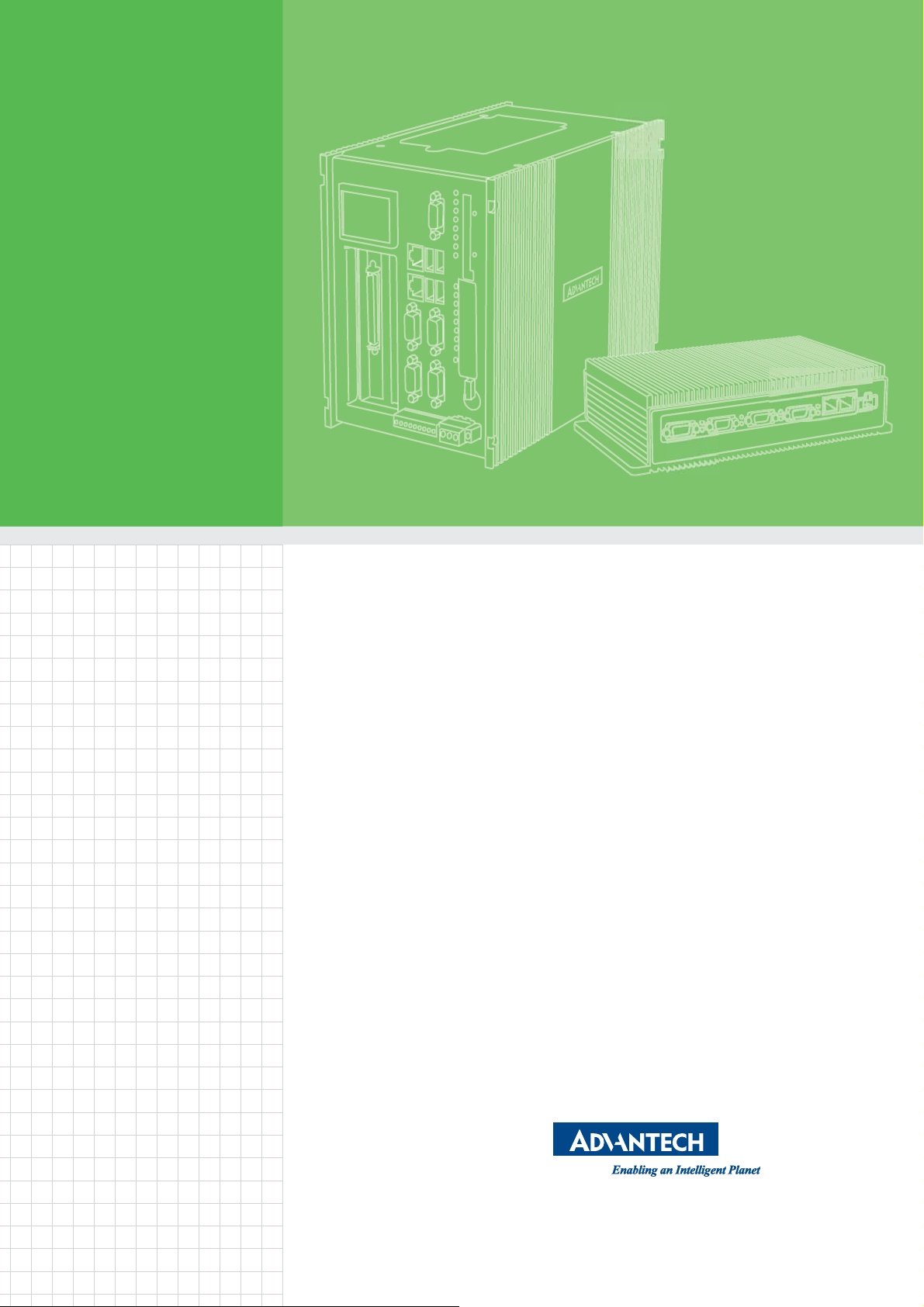
User Manual
UNO-2484G
電腦
Intel® Core™ i Standard-Size
Automation Computer with 4 x
GbE, 1 x mPCIe, 1 x HDMI, 1 x
DP, 4 x USB 3.0, and 4 x COM
Page 2
!
Ҕނ፦֖ԖݩҢᖂܴ!
!
ഢӜᆀǺġ
Equipment name
ႝတ
!
ࠠဦ
ȐࠠԄȑǺġ
Type designation
(Type)
UNO-2484G (سӈࠠဦፎୖـԛᇥܴ)
ൂϡ烤
nitġ
Ҕނ፦ϷځϯᏢ಄ဦ
ႉ
Leadġ
ĩőţĪġ
Mercuryġ
ĩʼnŨĪġ
ᙿ
Cadmiumġ
ĩńťĪġ
Ϥሽሐ
Hexavalent
chromium
ĩńų+6Ī
ӭྜྷᖄ
Polybrominated
biphenyls
ġ
ĩőŃŃĪġ
ӭྜྷΒ⾸
Polybrominated
diphenyl ethers
ġ
ĩőŃŅņĪġ
ႝၡ݈ġ ɡġ Ʉġ Ʉġ Ʉġ Ʉġ Ʉġ
ϣѦෘġġ
ĩѦෘǵϣ
ࢎǾ
Īġ
Ʉġ Ʉġ Ʉġ Ʉġ Ʉġ Ʉġ
ځѬڰۓ
ಔҹġġ
ĩᖥํĪġ
ɡġ Ʉġ Ʉġ Ʉġ Ʉġ Ʉġ
Ꮻьġ ɡġ Ʉġ Ʉġ Ʉġ Ʉġ Ʉġ
ഢԵIJįȺຬрıįIJġŸŵġĦȻϷȺຬрıįıIJġŸŵġĦȻ߯ࡰҔނ፦ϐԭϩК֖ໆຬрԭϩК֖ໆ୷ྗǶġ
ഢԵijįȺɄȻ߯ࡰ၀Ҕނ፦ϐԭϩК֖ໆ҂ຬрԭϩК֖ໆ୷ྗǶġ
ഢԵĴįȺɡȻ߯ࡰ၀Ҕނ፦ࣁ௨ନҞǶ
ġ
Declaration of the Presence Condition of the Restricted Substances Marking
Restricted substances and its chemical symbols
Note 1烉“Exceeding 0.1 wt %” and “exc eeding 0.01 wt %” indi cate that the percenta ge content of the restric ted substance exceeds the
reference percentage value of presence condition.
Note 2烉“˕” indicates that the percentage content of the rest ricted substance does not exceed the perc entage of reference value of presence.
Note 3烉The “−” indicates that the restricted substance corresponds to the exemption.
!
Ҕނ፦֖ԖݩҢᖂܴ!
!
ഢӜᆀǺġ
Equipment name
ႝတ
!
ࠠဦ
ȐࠠԄȑǺġ
Type designation
(Type)
UNO
2484G (سӈࠠဦፎୖـԛᇥܴĪ
ൂϡ烤
nitġ
Ҕނ፦ϷځϯᏢ಄ဦ
ႉ
Leadġ
ĩőţĪ
ġ
Mercury
ġ
ĩʼnŨĪġ
ᙿ
Cadmiumġ
ĩńťĪġ
Ϥሽሐ
Hexavalent
chromium
ĩńų+6Ī
ӭྜྷᖄ
Polybrominated
biphenyls
ġ
ĩőŃŃĪġ
ӭྜྷΒ⾸
Polybrominated
diphenyl ethers
ġ
ĩőŃŅņĪġ
ႝၡ݈ġ ɡġ Ʉġ Ʉġ Ʉġ Ʉġ Ʉġ
ϣѦෘġġ
ĩѦෘǵϣ
ࢎǾ
Īġ
Ʉġ Ʉġ Ʉġ Ʉġ Ʉġ Ʉġ
ځѬڰۓ
ಔҹġġ
ĩᖥํĪġ
ɡġ Ʉġ Ʉġ Ʉġ Ʉġ Ʉġ
Ꮻьġ ɡġ Ʉġ Ʉġ Ʉġ Ʉġ Ʉġ
ഢԵIJįȺຬрıįIJġŸŵġĦȻϷȺຬрıįıIJġŸŵġĦȻ߯ࡰҔނ፦ϐԭϩК֖ໆຬрԭϩК֖ໆ୷ྗǶġ
ഢԵijįȺɄȻ߯ࡰ၀Ҕނ፦ϐԭϩК֖ໆ҂ຬрԭϩК֖ໆ୷ྗǶġ
ഢԵĴįȺɡȻ߯ࡰ၀Ҕނ፦ࣁ௨ନҞǶ
ġ
Declaration of the Presence Condition of the Restricted Substances Marking
Restricted substances and its chemical symbols
Note 1烉“Exceeding 0.1 wt %” and “exc eeding 0.01 wt %” indica te that the percentage content of the restric ted substance exceeds the
reference percentage value of presence condition.
Note 2烉“˕” indicates that the percentage content of the rest ricted substance d oes not exceed the percentage of reference value of presence.
Note 3烉The “−” indicates that the restricted substance corresponds to the exemption.
UNO-2484G User Manual ii
Page 3

Copyright
Part No. 2003248402 Edition 3
Printed in Taiwan May 2018
The documentation and the software included with this product are copyrighted 2017
by Advantech Co., Ltd. All rights are reserved. Advantech Co., Ltd. reserves the right
to improve the products described in this manual at any time without notice. No part
of this manual may be reproduced, copied, translated or transmitted in any form or by
any means without the prior written permission of Advantech Co., Ltd. The information provided in this manual is intended to be accurate and reliable. However, Advantech Co., Ltd. assumes no responsibility for its use, nor for any infringements of the
rights of third parties, which may result from its use.
Acknowledgements
IBM, PC/AT, PS/2 and VGA are trademarks of International Business Machines Corporation.
Intel®, Core™ and Atom™ are the trademarks of Intel Corporation
Microsoft Windows and MS-DOS are registered trademarks of Microsoft Corp.
All other product names or trademarks are properties of their respective owners.
Support
For more information on this and other Advantech products, please visit our websites
at: http://www.advantech.com
For technical support and service, please visit our support website at:
http://support.advantech.com/
iii UNO-2484G User Manual
Page 4

This manual is applicable to the following models:
UNO-2484G, UNO2484G
UNO-2484G-6731AE, UNO-2484G-6731AE,
UNO-2484G-6531AE, UNO-2484G-6532AE,
UNO-2484G-6331AE, UNO-2484G-6332AE,
UNO2484G6731701E-T, UNO2484G6731702E-T, UNO2484G6731703E-T,
UNO2484G6731704E-T, UNO2484G6731705E-T, UNO2484G6731706E-T,
UNO2484G6731707E-T, UNO2484G6731708E-T, UNO2484G6731709E-T,
UNO2484G6731801E-T, UNO2484G6731802E-T, UNO2484G6731803E-T,
UNO2484G6731804E-T, UNO2484G6731805E-T, UNO2484G6731806E-T,
UNO2484G6731807E-T, UNO2484G6731808E-T, UNO2484G6731809E-T,
UNO2484G6731901E-T, UNO2484G6731902E-T, UNO2484G6731903E-T,
UNO2484G6731904E-T, UNO2484G6731905E-T, UNO2484G6731906E-T,
UNO2484G6731907E-T, UNO2484G6731908E-T, UNO2484G6731909E-T,
UNO2484G6732001E-T, UNO2484G6732002E-T, UNO2484G6732003E-T,
UNO2484G6732004E-T, UNO2484G6732005E-T, UNO2484G6732006E-T,
UNO2484G6732007E-T, UNO2484G6732008E-T, UNO2484G6732009E-T,
UNO2484G6732101E-T, UNO2484G6732102E-T, UNO2484G6732103E-T,
UNO2484G6732104E-T, UNO2484G6732105E-T, UNO2484G6732106E-T,
UNO2484G6732107E-T, UNO2484G6732108E-T, UNO2484G6732109E-T,
UNO2484G6732201E-T, UNO2484G6732202E-T, UNO2484G6732203E-T,
UNO2484G6732204E-T, UNO2484G6732205E-T, UNO2484G6732206E-T,
UNO2484G6732207E-T, UNO2484G6732208E-T, UNO2484G6732209E-T,
UNO2484G6531701E-T, UNO2484G6531702E-T, UNO2484G6531703E-T,
UNO2484G6531704E-T, UNO2484G6531705E-T, UNO2484G6531706E-T,
UNO2484G6531707E-T, UNO2484G6531708E-T, UNO2484G6531709E-T,
UNO2484G6531801E-T, UNO2484G6531802E-T, UNO2484G6531803E-T,
UNO2484G6531804E-T, UNO2484G6531805E-T, UNO2484G6531806E-T,
UNO2484G6531807E-T, UNO2484G6531808E-T, UNO2484G6531809E-T,
UNO2484G6531901E-T, UNO2484G6531902E-T, UNO2484G6531903E-T,
UNO2484G6531904E-T, UNO2484G6531905E-T, UNO2484G6531906E-T,
UNO2484G6531907E-T, UNO2484G6531908E-T, UNO2484G6531909E-T,
UNO2484G6532001E-T, UNO2484G6532002E-T, UNO2484G6532003E-T,
UNO2484G6532004E-T, UNO2484G6532005E-T, UNO2484G6532006E-T,
UNO2484G6532007E-T, UNO2484G6532008E-T, UNO2484G6532009E-T,
UNO2484G6532101E-T, UNO2484G6532102E-T, UNO2484G6532103E-T,
UNO2484G6532104E-T, UNO2484G6532105E-T, UNO2484G6532106E-T,
UNO2484G6532107E-T, UNO2484G6532108E-T, UNO2484G6532109E-T,
UNO2484G6532201E-T, UNO2484G6532202E-T, UNO2484G6532203E-T,
UNO2484G6532204E-T, UNO2484G6532205E-T, UNO2484G6532206E-T,
UNO2484G6532207E-T, UNO2484G6532208E-T, UNO2484G6532209E-T,
UNO2484G6331701E-T, UNO2484G6331702E-T, UNO2484G6331703E-T,
UNO2484G6331704E-T, UNO2484G6331705E-T, UNO2484G6331706E-T,
UNO-2484G User Manual iv
Page 5

UNO2484G6331707E-T, UNO2484G6331708E-T, UNO2484G6331709E-T,
UNO2484G6331801E-T, UNO2484G6331802E-T, UNO2484G6331803E-T,
UNO2484G6331804E-T, UNO2484G6331805E-T, UNO2484G6331806E-T,
UNO2484G6331807E-T, UNO2484G6331808E-T, UNO2484G6331809E-T,
UNO2484G6331901E-T, UNO2484G6331902E-T, UNO2484G6331903E-T,
UNO2484G6331904E-T, UNO2484G6331905E-T, UNO2484G6331906E-T,
UNO2484G6331907E-T, UNO2484G6331908E-T, UNO2484G6331909E-T,
UNO2484G6332001E-T, UNO2484G6332002E-T, UNO2484G6332003E-T,
UNO2484G6332004E-T, UNO2484G6332005E-T, UNO2484G6332006E-T,
UNO2484G6332007E-T, UNO2484G6332008E-T, UNO2484G6332009E-T,
UNO2484G6332101E-T, UNO2484G6332102E-T, UNO2484G6332103E-T,
UNO2484G6332104E-T, UNO2484G6332105E-T, UNO2484G6332106E-T,
UNO2484G6332107E-T, UNO2484G6332108E-T, UNO2484G6332109E-T,
UNO2484G6332201E-T, UNO2484G6332202E-T, UNO2484G6332203E-T,
UNO2484G6332204E-T, UNO2484G6332205E-T, UNO2484G6332206E-T,
UNO2484G6332207E-T, UNO2484G6332208E-T, UNO2484G6332209E-T,
UNO-2484G-7731AE, UNO-2484G-7531AE, UNO-2484G-7331AE
UNO-2484G-7732AE, UNO-2484G-7532AE, UNO-2484G-7332AE
UNO2484G7731801E-T, UNO2484G7731802E-T, UNO2484G7731803E-T
UNO2484G7731804E-T, UNO2484G7731805E-T
UNO2484G7731806E-T, UNO2484G7731807E-T, UNO2484G7731808E-T
UNO2484G7731809E-T, UNO2484G7731810E-T
UNO2484G7731901E-T, UNO2484G7731902E-T, UNO2484G7731903E-T
UNO2484G7731904E-T, UNO2484G7731905E-T
UNO2484G7731906E-T, UNO2484G7731907E-T, UNO2484G7731908E-T
UNO2484G7731909E-T, UNO2484G7731910E-T
UNO2484G7732001E-T, UNO2484G7732002E-T, UNO2484G7732003E-T
UNO2484G7732004E-T, UNO2484G7732005E-T
UNO2484G7732006E-T, UNO2484G7732007E-T, UNO2484G7732008E-T
UNO2484G7732009E-T, UNO2484G7732010E-T
UNO2484G7732101E-T, UNO2484G7732102E-T, UNO2484G7732103E-T
UNO2484G7732104E-T, UNO2484G7732105E-T
UNO2484G7732106E-T, UNO2484G7732107E-T, UNO2484G7732108E-T
UNO2484G7732109E-T, UNO2484G7732110E-T
UNO2484G7732201E-T, UNO2484G7732202E-T, UNO2484G7732203E-T
UNO2484G7732204E-T, UNO2484G7732205E-T
UNO2484G7732206E-T, UNO2484G7732207E-T, UNO2484G7732208E-T
UNO2484G7732209E-T, UNO2484G7732210E-T
UNO2484G7531801E-T, UNO2484G7531802E-T, UNO2484G7531803E-T
UNO2484G7531804E-T, UNO2484G7531805E-T
UNO2484G7531806E-T, UNO2484G7531807E-T, UNO2484G7531808E-T
UNO2484G7531809E-T, UNO2484G7531810E-T
UNO2484G7531901E-T, UNO2484G7531902E-T, UNO2484G7531903E-T
UNO2484G7531904E-T, UNO2484G7531905E-T
UNO2484G7531906E-T, UNO2484G7531907E-T, UNO2484G7531908E-T
UNO2484G7531909E-T, UNO2484G7531910E-T
UNO2484G7532001E-T, UNO2484G7532002E-T, UNO2484G7532003E-T
UNO2484G7532004E-T, UNO2484G7532005E-T
v UNO-2484G User Manual
Page 6

UNO2484G7532006E-T, UNO2484G7532007E-T, UNO2484G7532008E-T
UNO2484G7532009E-T, UNO2484G7532010E-T
UNO2484G7532101E-T, UNO2484G7532102E-T, UNO2484G7532103E-T
UNO2484G7532104E-T, UNO2484G7532105E-T
UNO2484G7532106E-T, UNO2484G7532107E-T, UNO2484G7532108E-T
UNO2484G7532109E-T, UNO2484G7532110E-T
UNO2484G7532201E-T, UNO2484G7532202E-T, UNO2484G7532203E-T
UNO2484G7532204E-T, UNO2484G7532205E-T
UNO2484G7532206E-T, UNO2484G7532207E-T, UNO2484G7532208E-T
UNO2484G7532209E-T, UNO2484G7532210E-T
UNO2484G7331801E-T, UNO2484G7331802E-T, UNO2484G7331803E-T
UNO2484G7331804E-T, UNO2484G7331805E-T
UNO2484G7331806E-T, UNO2484G7331807E-T, UNO2484G7331808E-T
UNO2484G7331809E-T, UNO2484G7331810E-T
UNO2484G7331901E-T, UNO2484G7331902E-T, UNO2484G7331903E-T
UNO2484G7331904E-T, UNO2484G7331905E-T
UNO2484G7331906E-T, UNO2484G7331907E-T, UNO2484G7331908E-T
UNO2484G7331909E-T, UNO2484G7331910E-T
UNO2484G7332001E-T, UNO2484G7332002E-T, UNO2484G7332003E-T
UNO2484G7332004E-T, UNO2484G7332005E-T
UNO2484G7332006E-T, UNO2484G7332007E-T, UNO2484G7332008E-T
UNO2484G7332009E-T, UNO2484G7332010E-T
UNO2484G7332101E-T, UNO2484G7332102E-T, UNO2484G7332103E-T
UNO2484G7332104E-T, UNO2484G7332105E-T
UNO2484G7332106E-T, UNO2484G7332107E-T, UNO2484G7332108E-T
UNO2484G7332109E-T, UNO2484G7332110E-T
UNO2484G7332201E-T, UNO2484G7332202E-T, UNO2484G7332203E-T
UNO2484G7332204E-T, UNO2484G7332205E-T
UNO2484G7332206E-T, UNO2484G7332207E-T, UNO2484G7332208E-T
UNO2484G7332209E-T, UNO2484G7332210E-T
UNO-2484G User Manual vi
Page 7

Product Warranty (2 years)
Advantech warrants the original purchaser that all of its products will be free from
defects in materials and workmanship for two years from the date of purchase.
This warranty does not apply to any products that have been repaired or altered by
persons other than repair personnel authorized by Advantech, or that have been subject to misuse, abuse, accident, or improper installation. Advantech assumes no liability under the terms of this warranty as a consequence of such events.
Because of Advantech’s high quality control standards and rigorous testing, most
customers never need to use our repair service. If an Advantech product is defective,
it will be repaired or replaced free of charge during the warranty period. For out-ofwarranty repairs, customers will be billed according to the cost of replacement materials, service time, and freight. Please consult your dealer for more details.
If you believe your product is defective, follow the steps outlined below.
1. Collect all the information about the problem encountered. (For example, CPU
speed, Advantech products used, other hardware and software used, etc.) Note
anything abnormal and list any onscreen messages displayed when the problem occurs.
2. Call your dealer and describe the problem. Please have your manual, product,
and any relevant information readily available.
3. If your product is diagnosed as defective, obtain an return merchandize authori-
zation (RMA) number from your dealer. This allows us to process your return
more quickly.
4. Carefully pack the defective product, a completed Repair and Replacement
Order Card, and a proof of purchase date (such as a photocopy of your sales
receipt) into a shippable container. Product returned without a proof of purchase
date are not eligible for warranty service.
5. Write the RMA number clearly on the outside of the package and ship the pack-
age prepaid to your dealer.
Declaration of Conformity
CE
This product has passed the CE test for environmental specifications when shielded
cables are used for external wiring. We recommend the use of shielded cables. This
type of cable is available from Advantech. Please contact your local supplier for
ordering information.
FCC Class A
This equipment has been tested and found to comply with the limits for a Class A digital device, pursuant to part 15 of the FCC Rules. These limits are designed to provide reasonable protection against harmful interference when the equipment is
operated in a commercial environment. This equipment generates, uses, and can
radiate radio frequency energy and, if not installed and used in accordance with the
instruction manual, may cause harmful interference to radio communications. Operation of this equipment in a residential area is likely to cause harmful interference. In
such cases, users are required to correct the interference at their own expense.
vii UNO-2484G User Manual
Page 8

警告使用者
這是甲類測試產品,在居住的環境中使用時,可能會造成射頻干擾,在這種情況下,
使用者會被要求採取某些適當的對策。
Technical Support and Assistance
1. Visit the Advantech website at www.advantech.com/support to obtain the latest
product information.
2. Contact your distributor, sales representative, or Advantech's customer service
center for technical support if you need additional assistance. Please have the
following information ready before you call:
– Product name and serial number
– Description of your peripheral attachments
– Description of your software (operating system, version, application software,
etc.)
– A comprehensive description of the problem
– The exact wording of any error messages
Safety Precaution - Static Electricity
Follow these simple precautions to protect yourself from harm and the products from
damage.
To avoid electrical shock, always disconnect the power from your PC chassis
before manual handling. Do not touch any components on the CPU card or
other cards while the PC is powered on.
Disconnect the power before making any configuration changes. The sudden
rush of power after connecting a jumper or installing a card may damage sensitive electronic components.
UNO-2484G User Manual viii
Page 9

Safety Instructions
1. Read these safety instructions carefully.
2. Retain this user manual for future reference.
3. Disconnect the equipment from all AC outlets before cleaning. Use only a damp
cloth for cleaning. Do not use liquid or spray detergents.
4. For pluggable equipment, the power outlet socket must be located near the
equipment and easily accessible.
5. Protect the equipment from humidity.
6. Place the equipment on a reliable surface during installation. Dropping or letting
the equipment fall may cause damage.
7. The openings on the enclosure are for air convection. Protect the equipment
from overheating. Do not cover the openings.
8. Ensure that the power source voltage is correct before connecting the equip-
ment to a power outlet.
9. Position the power cord away from high-traffic areas. Do not place anything over
the power cord.
10. All cautions and warnings on the equipment should be noted.
11. If the equipment is not used for a long time, disconnect it from the power source
to avoid damage from transient overvoltage.
12. Never pour liquid into an opening. This may cause fire or electrical shock.
13. Never open the equipment. For safety reasons, the equipment should be
opened only by qualified service personnel.
14. If one of the following situations occurs, have the equipment checked by service
personnel:
– The power cord or plug is damaged.
– Liquid has penetrated into the equipment.
– The equipment has been exposed to moisture.
– The equipment is malfunctioning, or does not operate according to the user
manual.
– The equipment has been dropped and damaged.
– The equipment shows obvious signs of breakage.
15. Do not leave this equipment in an environment where the storage temperature
may fluctuate below -20 °C (-4 °F) or above ~ 60 °C (140 °F).
16. Batteries are at risk of exploding if incorrectly replaced. Replace only with the
same or equivalent type as recommended by the manufacturer. Discard used
batteries according to the manufacturer’s instructions.
17. Danger d'explosion si la batterie est mal remplace. Remplacer uniquement par
le meme type ou equivalent recommandé par le fabricant. Jeter les piles usagées selon les instructions du fabricant.
18. In accordance with the IEC 704-1:1982 specifications, the sound pressure level
at the operator position does not exceed 70 dB (A).
DISCLAIMER: These instructions are provided according to IEC 704-1. Advantech
disclaims all responsibility for the accuracy of any statements contained herein.
ix UNO-2484G User Manual
Page 10

安全指示
1.請仔細閱讀此安全操作說明。
2.請妥善保存此用戶手冊供日後參考。
3.用濕抹布清洗設備前,請確認拔除電源線。請勿使用液體或去污噴霧劑清洗
設備。
4.對於使用電源線的設備,設備周圍必須有容易接觸到的電源插座。
5.請勿在潮濕環境中試用設備。
6.請在安裝前確保設備放置在可靠的平面上,意外摔落可能會導致設備損壞。
7.設備機殼的開孔適用於空氣對,從而防止設備過熱。請勿覆蓋開孔。
8.當您連接設備到電源插座前,請確認電源插座的電壓符合要求。
9.請將電源線佈置在人們不易絆倒的位置,請勿在電源線上覆蓋任何雜物。
10.請注意設備上所有的警告標示。
11.如果長時間不使用設備,請拔除與電源插座的連結,避免設備被超標的電
壓波動損壞。
12.請勿讓任何液體流入通風口,以免引起火灾或短路。
13.請勿自行打開設備。為了確保您的安全,請透過經認證的工程師來打開設
備。
14.如遇下列情况,請由專業人員維修:
電源線或插頭損壞;
設備內部有液體流入;
設備曾暴露在過度潮濕環境中使用;
設備無法正常工作,或您無法透過用戶手冊來正常工作;
設備摔落或損壞;
設備有明顯外觀損;
15.請勿將設備放置在超出建議溫度範圍的環境,即不要低於 -20 ℃(‐4℉)
或高於 60℃(140℉),否則可能會造成設備損壞。
16.注意:若電池更換不正確,將有爆炸危險。因此,只可以使用製造商推薦
的同一種或者同等型號的電池進行替換。請按照製造商的指示處理舊電池。
17.根據 IEC704‐1:1982規定,操作員所在位置音量不可高於 70分貝。
18.限制區域:請勿將設備安裝於限制區域使用。
19.免責聲明:請安全訓示符合 IEC704‐1要求。研華公司對其內容之準確性不
承擔任何法律責任。
UNO-2484G User Manual x
Page 11

Contents
Chapter 1 Overview...............................................1
1.1 Introduction ............................................................................................... 2
1.2 Safety Precautions .................................................................................... 2
1.3 Accessories............................................................................................... 3
Chapter 2 Hardware Functionality.......................5
2.1 Introduction ............................................................................................... 6
Figure 2.1 Front panel of the UNO-2484G single-stack model.... 6
Figure 2.2 Front panel of the UNO2484G dual-stack model .......6
2.2 UNO-2484G Interface ............................................................................... 6
2.2.1 COM Port Interface (COM1, COM2, COM3, COM4) .................... 6
2.3 LAN: Ethernet Connector .......................................................................... 6
2.4 Power Connector ...................................................................................... 6
2.5 USB Connector ......................................................................................... 7
2.6 RTC Battery .............................................................................................. 7
2.7 Power Button/Power Management ........................................................... 7
2.8 Reset Button ............................................................................................. 7
2.9 PCI Express Mini Card Socket.................................................................. 7
Figure 2.3 First stack motherboard.............................................. 8
Figure 2.4 Second stack extension board ................................... 8
Chapter 3 Initial Setup ..........................................9
3.1 Chassis Grounding.................................................................................. 10
Figure 3.1 Chassis grounding connection ................................. 10
3.2 Connect the Power Supply...................................................................... 10
3.3 Open/Close the Rear Cover.................................................................... 11
3.4 Hard Disk Installation .............................................................................. 13
3.4.1 HDD/SSD Installation for Single-Stack UNO-2484G .................. 13
3.4.2 HDD/SSD Installation for Double-Stack UNO-2484G ................. 15
3.4.3 HDD/SSD Installation with UNO-2484G-S2AE Extension Module .
....................................................................................................19
3.5 Extension Kit (UNO-2484G-EKAE) Installation....................................... 23
Appendix A System Settings/Pin Assignments ..25
A.1 CN10 Internal GPIO Pin Header ............................................................. 26
Table A.1: CN10 Internal GPIO Pin Header .............................. 26
A.2 Board Connectors and Jumpers ............................................................. 26
Figure A.1 Connector and jumper locations (front view)............ 27
Table A.2: Connectors and Jumpers ......................................... 27
A.3 Power Connector (PWR)......................................................................... 28
Table A.3: Power Connector Pin Assignments.......................... 28
A.4 DP Connector.......................................................................................... 28
Table A.4: DisplayPort Adaptor Cable Pin Assignments ........... 28
Table A.5: USB 3.0 Connector Pin Assignments....................... 29
A.5 HDMI Display Connector......................................................................... 29
Table A.6: HDMI Display Connector .......................................... 29
A.6 COM1/COM2/COM3/COM4 RS232/422/485 Connector ........................ 30
A.7 Mini PCIE Slot (MINIPCIE)...................................................................... 31
A.8 LAN RJ45 Connector .............................................................................. 32
xi UNO-2484G User Manual
Page 12

A.9 CN15/CN53 Internal USB 2.0 Pin Header .............................................. 33
Table A.7: CN15/CN53 Internal USB 2.0 Pin Header................ 33
A.10 Screw Type and Quantity for Mounting Module...................................... 33
A.11 Modifying the Serial Port Mode............................................................... 34
A.12 BIOS Setting of TPM 2.0......................................................................... 36
UNO-2484G User Manual xii
Page 13

Chapter 1
1 Overview
This chapter provides an overview
of UNO-2484G specifications.
Introduction
Safety Precautions
Accessories
Page 14
1.1 Introduction
The UNO-2484G is an embedded hardware-ready platform capable of shortening
development time. The system offers a wide range of networking interfaces to satisfy
the various needs of different applications. Equipped with the latest Intel® Core™ i
processor, 8 GB of DDR4 RAM, four GbE LAN, and four USB 3.0 ports, the UNO2484G supports one DP and one HDMI display as well as Advantech’s iDoor modules.
The UNO-2484G can tolerate a wide operating temperature range (-20 ~ 60 °C) and
features one mini PCIe (or three additional mPCIe ports via a mini-card extender) for
convenient expansion. This allows the UNO-2484G to be integrated with Wi-Fi, 3G,
and I/O expansion modules and industrial protocols via iDoor technology.
With support for multiple drivers and operating systems, including Windows 7, Windows 10, and Linux, users can easily integrate applications on application-ready platforms in order to offer versatile functions for diverse requirements.
1.2 Safety Precautions
The following sections provide instructions for setting up each connection. In most
cases, users will simply need to connect a standard cable.
Warning! Always disconnect the power cord from the chassis before manual han-
dling. Do not make any configuration changes when the power is on.
The sudden rush of power can damage sensitive electronic components. Only experienced electronics personnel should open the chassis.
Warning! Toujours à la terre pour éliminer toute charge d'électricité statique avant
toucher UNO-2484G. Appareils électroniques modernes sont très sensibles à charges d'électricité statique. Utilisez un bracelet antistatique à
tout moment. Placez tous composants électroniques sur une surface
antistatique ou dans un statique-sac blindé.
Caution! Always ground yourself to remove any static electric charge before
touching UNO-2484G. Modern electronic devices are very sensitive to
static electric charges. Use a grounding wrist strap at all times. Place all
electronic components on a static-dissipative surface or in a staticshielded bag.
Caution! Toujours débrancher le cordon d'alimentation de votre boîtier lorsque
vous êtes travailler. Ne branchez pas lorsque l'appareil est allumé. Un
afflux soudain de puissance peut endommager les composants électroniques sensibles. Seulement connu personnel de l'électronique
devraient ouvrir le châssis.
UNO-2484G User Manual 2
Page 15

1.3 Accessories
The following accessories should be included with the product:
Pin connector for power wiring (Advantech P/N: 1652002209)
Warranty card
If any of the above items are missing or damaged, contact your distributor or sales
representative immediately.
Operating Temperature: -20 ~ 60 °C (-4 ~ 140 °F)
Power Requirements: 10 - 36 V
Power Consumption: 55 W (typical), 92.5 W (max.)
System Hardware Specifications
– CPU:
Intel® Core™ i7-7600U(2.8 GHz)/i7-7300U(2.6 GHz)/i7-7100U(2.4 GHz)
Intel® Core™ i7-6600U (2.6 GHz)/i5-6300U (2.4 GHz)/i3-6100U (2.3 GHz)
– Memory: 8 GB DDR4 2133 MHz
– Graphics Engine: Intel® HD Graphics
– Ethernet: Intel® i210 GbE, 802.10av, IEEE1588/802.1AS, 803.3az
– Storage:
Supports 2 x SSD or HDD (RAID support)
1 x full-size mSATA (supports mPCIe)
– Expansion: 1 x full-size mPCIe slot (can support an additional 3 x full-size
mPCIe with the integration of a secondary extension mini card)
– Display:1 x HDMI, supports 1920 x 1080 @60Hz 24bpp and 1 x DP
DC
Chapter 1 Overview
Because UNO-2484G features a modularized design, Advantech offers both single
and double-stack models.
Single-stack models:
UNO-2484G-6731AE/UNO-2484G-6531AE/UNO-2484G-6331AE
Double-stack models:
UNO-2484G-6732AE/UNO-2484G-6532AE/UNO-2484G-6332AE
The double-stack model combines a single-stack model with an extension kit (UNO2484G-EKAE) for integrating iDoor technology.
3 UNO-2484G User Manual
Page 16

UNO-2484G User Manual 4
Page 17

Chapter 2
2 Hardware
Functionality
This chapter explains how to
setup the UNO-2484G’s hardware
functions, including connecting
peripherals and setting switches
and indicators.
Introduction
UNO-2484G Interface
LAN/Ethernet Connector
Power Connector
USB Connector
RTC Battery
Power Button/Power Manage-
ment
Reset Button
PCI Express Mini Card Socket
Page 18

2.1 Introduction
The following figures show the connectors on UNO-2484G. Information regarding
each peripheral is provided in the following sections.
Figure 2.1 Front panel of the UNO-2484G single-stack model
Figure 2.2 Front panel of the UNO2484G dual-stack model
2.2 UNO-2484G Interface
he UNO-2484G is equipped with four standard COM serial communication ports –
COM1, COM2, COM3, and COM4. The port settings can be adjusted from the BIOS
menu. Drivers are installed automatically during OS installation.
2.2.1 COM Port Interface (COM1, COM2, COM3, COM4)
The UNO-2484G features four RS-232/422/485, DB9, 50 ~ 115.2 kbps.
2.3 LAN: Ethernet Connector
UNO-2484G is equipped with a four Gigabit LAN controller. The controller chip used
is an Intel i210 Ethernet controller that is fully compliant with IEEE 802.3u 10/100/
1000 Base-T. The Ethernet port is a standard RJ-45 jack, and LED indicators are on
the front to show its Link (Green LED) and Active (Green LED) status.
2.4 Power Connector
The UNO-2484G is equipped with a phoenix power connector that is compatible with
10 ~ 36 V
the system from damage caused by reversed wiring of ground and power lines. (For
more information, refer to Appendix A.4.)
external power and features reversed wiring protection. This protects
DC
UNO-2484G User Manual 6
Page 19

2.5 USB Connector
The USB interface supports plug-and-play functionality, which enables users to connect or disconnect a device at any time without powering off the system. Equipped
with four USB connectors, the UNO-2484G provides complete plug-and-play and
hot-swapping capabilities for up to 127 external devices. The USB interface can be
disabled in the system BIOS. Additionally, the provision of four USB ports complies
with USB EHCI, Rev. 3.0. (Refer to Appendix A.5 for pin assignments.)
2.6 RTC Battery
The UNO-2484G has an RTC battery to ensure that the BIOS and system clock settings are retained even after brief power disconnections.
Type: Panasonic BR2032
Output Voltage: 3 V
DC
2.7 Power Button/Power Management
Press the “PWR” button to power on or power off the UNO-2484G(ATX type). The
UNO-2484G supports the ACPI (Advanced Configuration and Power Interface).
Besides power on/off, it supports multiple suspend modes, such as Power on Suspend (S1), Suspend to RAM (S3), Suspend to Disk (S4). In S3 and S4 suspend
mode, the power consumption can be less than 2W, which meets Energy Star
requirements.
Chapter 2 Hardware Functionality
2.8 Reset Button
Press the “Reset” button to activate the hardware reset function.
2.9 PCI Express Mini Card Socket
The UNO-2484G single-stack model supports one full-size socket for PCI Express
mini cards.The (MINI1) interface supports USB, PCIe, and mSATA signals and can
automatically detect the device type to provide the required support. This function
can be accessed via Wi-Fi, 3G communication module, or mSATA SSD.
The UNO-2484G double-stack model combines a single-stack model with an UNO2484G-EKAE extension kit. In addition to the mini PCIe slot on the first stack, the
double-stack model also supports three additional full-size PCI Express mini card
sockets on the second stack. The MINI1 interface on the second stack supports USB
and PCIe signals. The MINI2 and MINI3 interfaces only support PCIe signals.
Note! In addition to the mini PCIe (MINI1) socket, the system features a SIM
card slot for supporting 3G/LTE functionality. However, users are
required to install a 3G/LTE mini PCIe module to enable this function.
7 UNO-2484G User Manual
Page 20
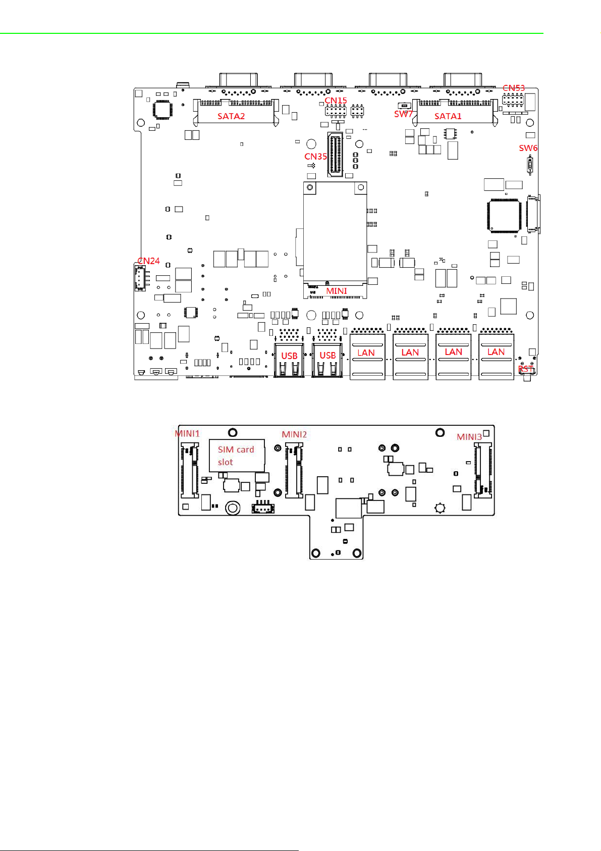
Figure 2.3 First stack motherboard
Figure 2.4 Second stack extension board
UNO-2484G User Manual 8
Page 21

Chapter 3
3 Initial Setup
This chapter explains the process
for initializing the UNO-2484G.
Chassis Grounding
Connect the Power Supply
Open/Close the Rear Cover
Hard Disk Installation
Extension Kit Installation
Page 22

3.1 Chassis Grounding
The UNO-2484G provides adequate EMI protection and a stable grounding base.
Moreover, an easy-to-connect chassis grounding point is also provided.
Figure 3.1 Chassis grounding connection
3.2 Connect the Power Supply
The UNO-2484G is intended to be supplied by a listed power adapter or DC power
source rated 10 ~ 36V
please contact Advantech for additional information.
DC, 8A, and TMA 60 °C. Should you require further assistance,
UNO-2484G User Manual 10
Page 23

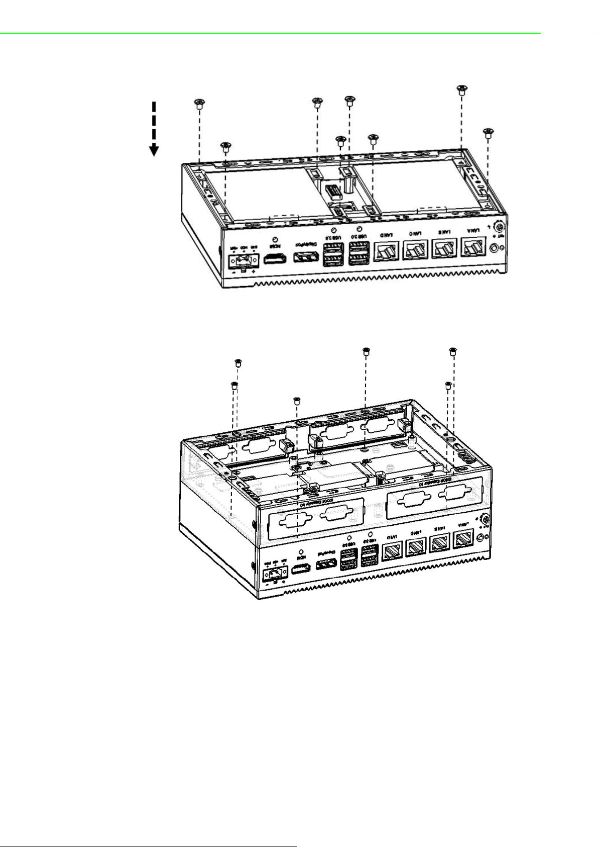
3.3 Open/Close the Rear Cover
The rear cover can be opened in order to install a mPCIe module, mSATA SSD, or
HDD, or to adjust the switch settings.
Open the Rear Cover
1. Remove the four rubber feet.
2. Remove the two affixing screws of the rear cover.
Chapter 3 Initial Setup
3. Slide to open the rear cover.
11 UNO-2484G User Manual
Page 24

Close the Rear Cover:
1. Align the guide pillars between the rear cover and bracket then slide the rear
cover in place and fix in position.
2. Secure the rear cover in place using two screws. Then attach the four rubber
feet.
UNO-2484G User Manual 12
Page 25

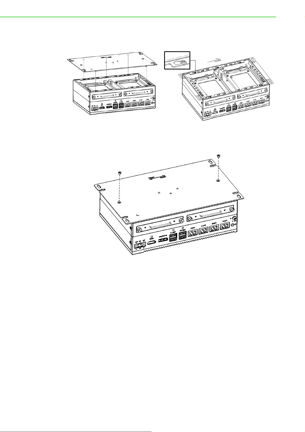
3.4 Hard Disk Installation
3.4.1 H DD/SSD Installation for Single-Stack UNO-2484G
1. Remove the rear cover
2. Remove the HDD bracket by unscrewing the four affixing screws on the HDD
bracket
Chapter 3 Initial Setup
3. Attach the HDD/SSD to the HDD bracket using screws
13 UNO-2484G User Manual
Page 26
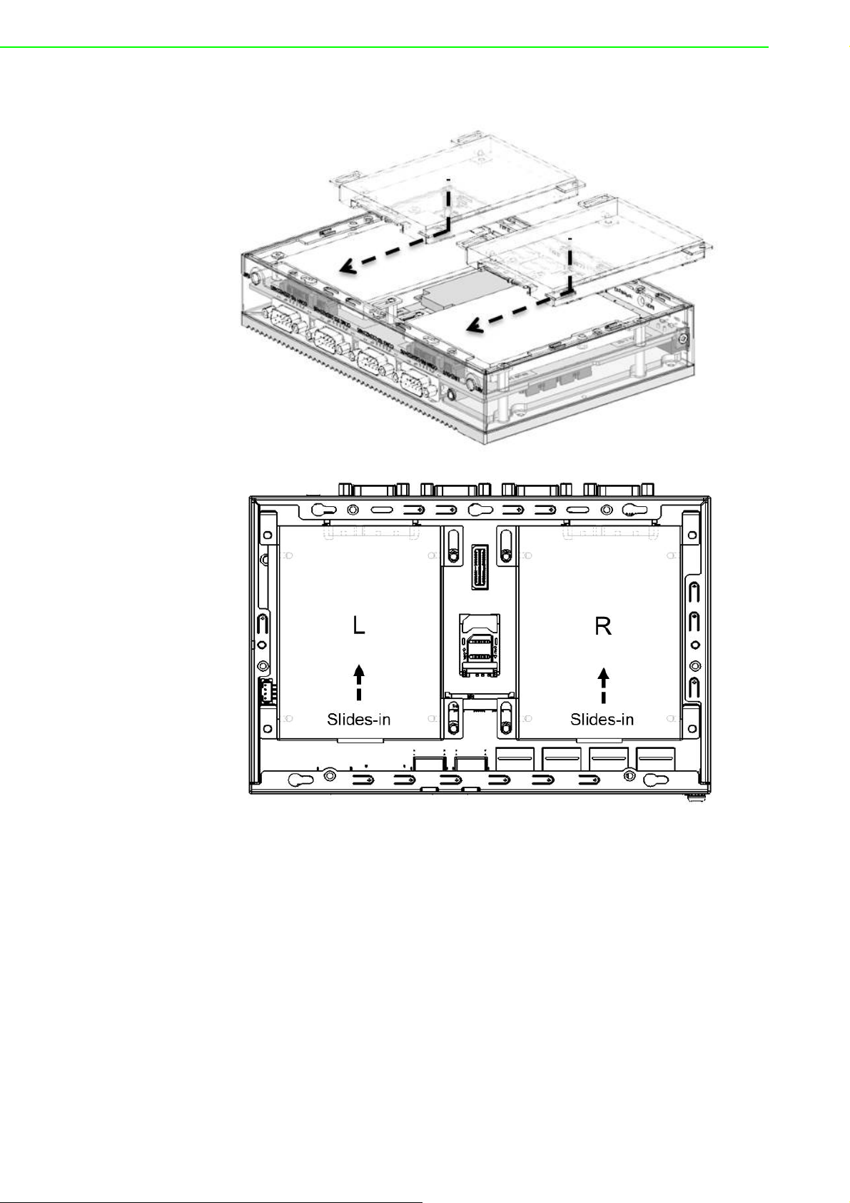
4. Slide the HDD/SDD attached to the bracket into the chassis
UNO-2484G User Manual 14
Page 27

5. Secure the HDD bracket in place using four screws
6. Replace the rear cover.
Chapter 3 Initial Setup
3.4.2 HDD/SSD Installation for Double-Stack UNO-2484G
1. Remove the rear cover.
2. Unscrew the five affixing screws to remove the second stack extension kit
15 UNO-2484G User Manual
Page 28

3. Remove the HDD bracket by unscrewing the four screws on the HDD bracket
4. Attach the HDD/SSD to the HDD bracket using screws
UNO-2484G User Manual 16
Page 29

5. Slide the HDD/SDD attached to the bracket into the chassis
Chapter 3 Initial Setup
17 UNO-2484G User Manual
Page 30
6. Affix the HDD bracket in place using four screws
7. Reattach the second stack extension kit using five screws.
8. Replace the rear cover.
UNO-2484G User Manual 18
Page 31
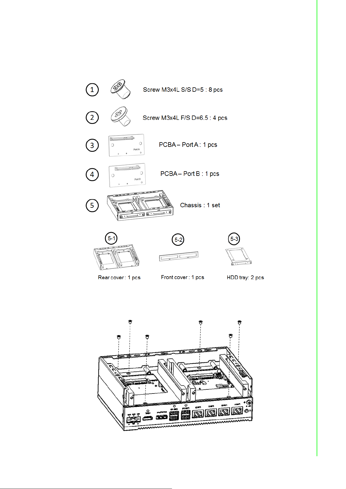
3.4.3 HDD/SSD Installation with UNO-2484G-S2AE Extension
Module
Below is the list of components provided with the UNO-2484G-S2AE extension module.
Chapter 3 Initial Setup
1. Secure the second stack extension kit rear cover (5-1) in place using the screws
provided (1).
19 UNO-2484G User Manual
Page 32
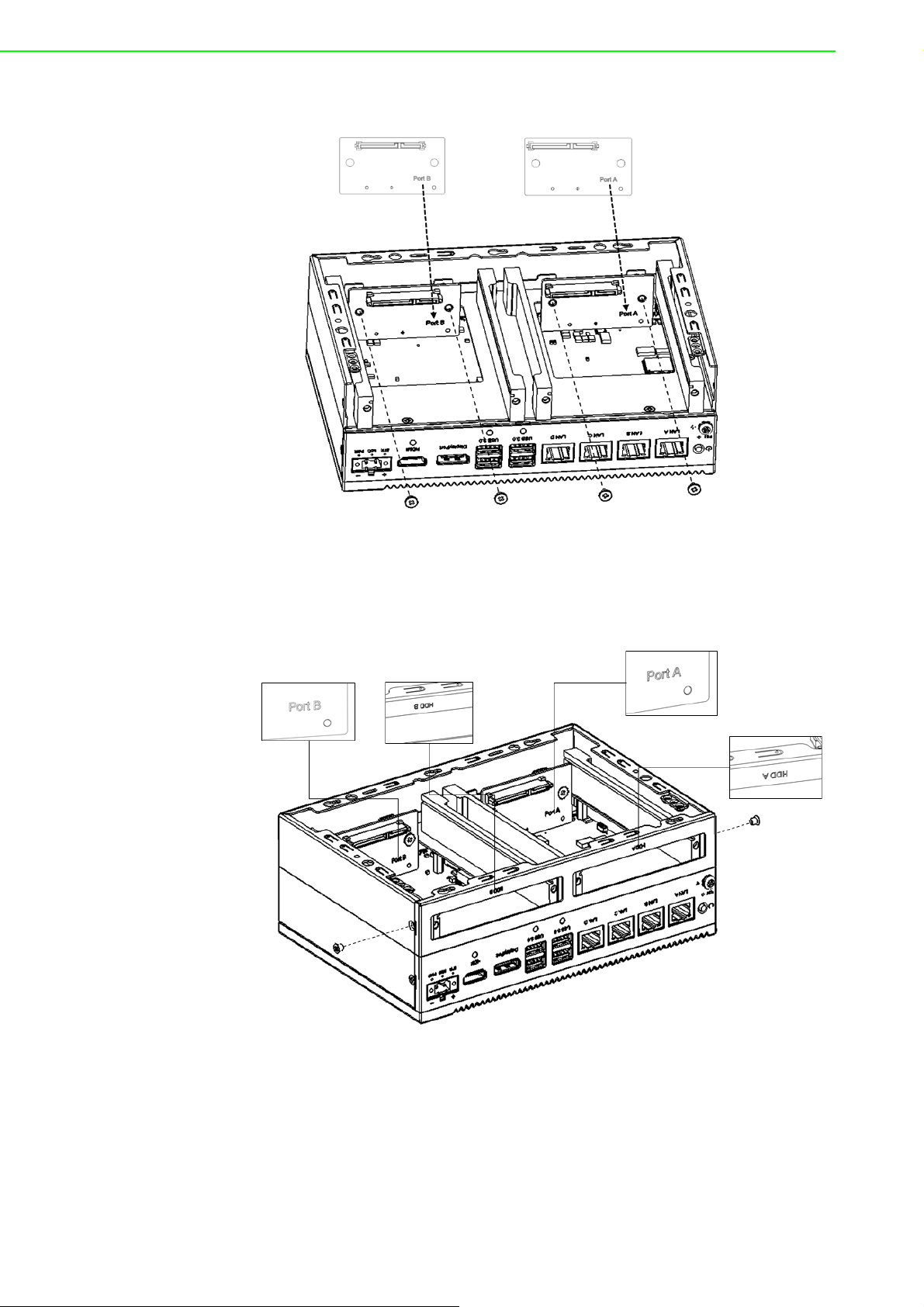
2. Lock PCBA Port A (3) and Port B (3) with screws (2).
3. Secure the front cover (5-2) in place using the screws provided (1). Ensure that
the HDD A port of the front cover and Port A on the PCBA are located on the
same side.
UNO-2484G User Manual 20
Page 33

4. Secure the HDD to the HDD tray (5-3) using the screws located at the internal
side of the first stack layer.
5. Insert the HDD with tray into the slot and tighten the thumb screws.
Chapter 3 Initial Setup
21 UNO-2484G User Manual
Page 34
6. Align the guide pillars between the rear cover and bracket, and then slide the
rear cover in place to fix in position.
7. Secure the rear cover in place using the screws provided. Then attach the rub-
ber feet.
UNO-2484G User Manual 22
Page 35

3.5 Extension Kit (UNO-2484G-EKAE) Installation
1. Remove the rear cover
2. Attach the second extension kit stack to the first stack.
Chapter 3 Initial Setup
3. Secure the rear cover in place using the two screws provided. Then attach the
four rubber feet.
23 UNO-2484G User Manual
Page 36

UNO-2484G User Manual 24
Page 37

Appendix A
A System Settings/Pin
Assignments
Page 38

A.1 CN10 Internal GPIO Pin Header
Table A.1: CN10 Internal GPIO Pin Header
Pin Signal
1+5V
2GPIO0
3GPIO1
4GPIO2
5GPIO3
6GPIO4
7GPIO5
8GPIO6
9GPIO7
10 GND
A.2 Board Connectors and Jumpers
The UNO-2484G board features several connectors and jumpers. The following sections explain how to configure the UNO-2484G hardware settings.
UNO-2484G User Manual 26
Page 39

Appendix A System Settings
/
Figure A.1 Connector and jumper locations (front view)
Table A.2: Connectors and Jumpers
Label Function
DCIN Power-in connector
HDMI HDMI connector
DP DisplayPort connector
USB USB 3.0 connector
LAN RJ45 connector
PWR Power button
RST Reset button
COM COM port connector
COM5/COM7 Internal COM port pin header
MINI PCI Express mini card socket/mSATA
SATA1/SATA2 SATA connector
CN4 RTC battery connector
CN10 Internal GPIO pin header
CN15/CN53 Internal USB 2.0 pin header
CN21 Audio line-out
CN24
CN35
SW6
SW7
SW8
Internal power connector; the voltage is the same as that for DCIN
Board-to-board connector
AT/ATX mode switch. ON -> ATX mode, OFF -> AT mode.
Clear COMS switch. Pin 1 -> normal, Pin 3 -> Clear
Disable internal COM5~8, Pin (1-2) -> enable, Pin (3-4) -> disable
Pin Assignments
27 UNO-2484G User Manual
Page 40

A.3 Power Connector (PWR)
Table A.3: Power Connector Pin Assignments
Pin Signal Description
1 Power-In V+
2 Power-In V- (GND)
A.4 DP Connector
10 ~ 36V
DC
Table A.4: DisplayPort Adaptor Cable Pin Assignments
Pin Signal Name
1 ML_Lane 0 (p)
2GND
3 ML_Lane 0 (n)
4 ML_Lane 1 (p)
5GND
6 ML_Lane 1 (n)
7 ML_Lane 2 (p)
8GND
9 ML_Lane2 (2)
10 ML_Lane 3 (p)
11 GND
12 ML_Lane 3 (n)
13 CONFIG1
14 CONFIG2
15 AUX CH (p)
16 GND
17 AUX CH (n)
18 Hot Plug
19 Return
20 DP_PWR
UNO-2484G User Manual 28
Page 41

/
Table A.5: USB 3.0 Connector Pin Assignments
Pin Signal Name Description
1 VBUS Power
2D-
3D+
4 GND Ground for power return
5 StdA_SSRX-
6 StdA_SSRX+
7 GND_DRIAN Ground for signal return
8 StdA_SSTX-
9 StdA_SSTX+
USB2.0 differential pair
SuperSpeed receiver differential pair
SuperSpeed transmitter differential pair
Appendix A System Settings
A.5 HDMI Display Connector
Table A.6: HDMI Display Connector
Pin Signal Pin Signal
1 TMDS Data2+ 2 TMDS Data2 Shield
3 TMDS Data2- 4 TMDS Data1+
5 TMDS Data1 Shield 6 TMDS Data1-
7 TMDS Data0+ 8 TMDS Data0 Shield
9 TMDS Data0- 10 TMDS Clock+
11 TMDS Clock Shield 12 TMDS Clock-
13 CEC 14 Reserved
15 SCL 16 SDA
17 DDC/CEC/HEC Ground 18 +5 V Power (max. 50 mA)
19 Hot Plug Detect
Pin Assignments
29 UNO-2484G User Manual
Page 42
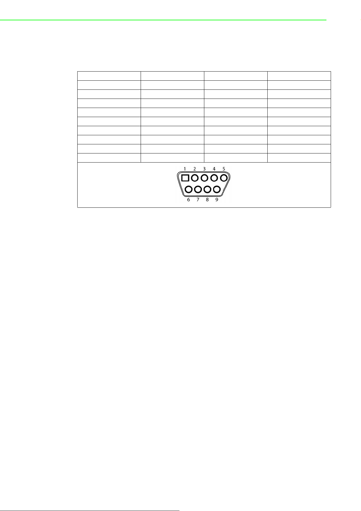
A.6 COM1/COM2/COM3/COM4 RS232/422/485
Connector
Pin RS232 RS422 RS485
1 DCD TX- D-
2RXTX+D+
3TXRX+
4DTRRX-
5GNDGNDGND
6DSR
7RTS
8CTS
9RI
UNO-2484G User Manual 30
Page 43

/
A.7 Mini PCIE Slot (MINIPCIE)
Supports PCI1.1, PCI1.2 power definition.
Pin Signal Description Pin Signal Description
+3.3Vaux /
52
+3.3V
50 GND 49 Reserved NC
48 +1.5V 47 Reserved NC
46 NC NC 45 Reserved NC
44 NC NC 43
42 NC NC 41 +3.3Vaux
40 GND 39 +3.3Vaux
38 USB_D+
36 USB_D- 35 GND
34 GND 33 PETp0 PCI Express differential transmit pair
32 SMB_DATA
30 SMB_CLK 29 GND
28 +1.5V 27 GND
26 GND 25 PERp0 PCI Express differential receive pair
24 +3.3Vaux 23 PERn0
22 PERST# Functional reset to the card 21 GND
W_DISABLE
20
#
18 GND 17 Reserved NC
Key Key Key Key
16 NC NC 15 GND
14 NC NC 13 REFCLK+
12 NC NC 11 REFCLK-
10 NC NC 9 GND
8 NC NC 7 CLKREQ# Reference clock request signal
6 1.5V 5 NC NC
4GND 3NC NC
+3.3Vaux /
2
+3.3V
PCI1.1 was +3.3V, PCI1.2 was +3.3Vaux 51 Reserved NC
USB serial data interface compliant to
the USB 2.0 specification
SMBus data signal compliant to the
SMBus 2.0 specification
Active low signal. This signal is used by
the system to disable radio operation on
add-in cards that implement radio frequency applications. When implemented,
this signal requires a pull-up resistor on
the card.
PCI1.1 was +3.3V , PCI1.2 was
+3.3Vaux
37 GND
31 PETn0
19 Reserved NC
1 WAKE#
PIN43_MPCIE_
PWRSEL
The pin to select the Pin 2, 52 power
output for +3.3Vaux or +3.3V (PCI1.1
was Reserved and PIC1.2 was GND
Open drain active low signal. This signal is used to request that the system
return from a sleep/suspended state to
service a function initiated wake event.
Appendix A System Settings
Pin Assignments
Note 1: +3.3V aux is suspend power; power out to device +3.3V/1.1A
Note 2: +3.3V is core power
Note 3: +1.5V is core power; power out to device +1.5V/0.5A
31 UNO-2484G User Manual
Page 44

A.8 LAN RJ45 Connector
RJ45 Pin Signal Description
In BASE-T: Media-dependent interface[0]:
1 MDI0+
2 MDI0-
3 MDI1+
6 MDI1-
1000BASE-T: In MDI configuration, MDI[0]+/- corre-
sponds to BI_DA+/- and in MDI-X configuration MDI[0]+/corresponds to BI_DB+/-.
10BASE-T and 100BASE-TX: In MDI configuration,
MDI[0]+/- is used for the transmit pair and in MDIX
configuration MDI[0]+/- is used for the receive pair.
In BASE-T: Media-dependent interface[1]:
1000BASE-T: In MDI configuration, MDI[1]+/- corre-
sponds to BI_DB+ and in MDI-X configuration MDI[1]+/corresponds to BI_DA+/-.
10BASE-T and 100BASE-TX: In MDI configuration,
MDI[1]+/- is used for the receive pair and in MDI-X
configuration MDI[1]+/- is used for the transmit pair.
4MDI2+
In BASE-T: Media-dependent interface[3:2]:
1000BASE-T: In MDI and in MDI-X configuration,
MDI[2]+/- corresponds to BI_DC+/- and MDI[3]+/- corre-
5MDI2-
sponds to BI_DD+/-.
100BASE-TX: Unused.
7MDI3+
8MDI3-
10Link 100Link 1000 Link Active
Off Orange Green Green
10BASE-T: Unused.
Left LED Right LED
UNO-2484G User Manual 32
Page 45

/
A.9 CN15/CN53 Internal USB 2.0 Pin Header
Table A.7: CN15/CN53 Internal USB 2.0 Pin Header
Pin Signal
1+5V
2+5V
3USB1-
4USB2-
5USB1+
6USB2+
7GND
8GND
9NC
Appendix A System Settings
Pin Assignments
A.10 Screw Type and Quantity for Mounting Module
33 UNO-2484G User Manual
Page 46

A.11 Modifying the Serial Port Mode
The default setting for the serial ports is RS-232 mode. The setting can be configured
to RS-422 or RS-485 modes by following the instructions below.
1. Power on the UNO-2484G device and press "Delete" to enter the BIOS configu-
ration menu.
2. Select "Advanced"=>”IT8768E Super IO Configuration”.
3. Select the serial port (e.g., select “Serial Port 1 Configuration”).
UNO-2484G User Manual 34
Page 47

/
Appendix A System Settings
4. Select “COM1 mode” and choose from “RS232 mode”, “RS422 mode”, or
“RS485 mode”.
Pin Assignments
35 UNO-2484G User Manual
Page 48

A.12 BIOS Setting of TPM 2.0
The UNO-2484G series supports TPM2.0 function. This function can be enabled or
disabled in the BIOS configuration menu by following the instructions below.
1. Power on the UNO-2484G device and press “Delete” to enter the BIOS configu-
ration menu.
2. Select “Advanced”=> “Trusted Computing”.
3. Select “Security Device Support”.
UNO-2484G User Manual 36
Page 49

/
4. Choose “Enabled” or “Disabled” to enable/disable TPM2.0 function in the BIOS
menu.
Appendix A System Settings
Pin Assignments
37 UNO-2484G User Manual
Page 50

UNO-2484G User Manual 38
Page 51

Appendix A System Settings
/
Pin Assignments
39 UNO-2484G User Manual
Page 52

www.advantech.com
Please verify specifications before quoting. This guide is intended for reference
purposes only.
All product specifications are subject to change without notice.
No part of this publication may be reproduced in any form or by any means,
such as electronically, by photocopying, recording, or otherwise, without prior
written permission from the publisher.
All brand and product names are trademarks or registered trademarks of their
respective companies.
© Advantech Co., Ltd. 2017
 Loading...