

Advantech UNO-1252G-Q0AE, UNO-1252GQ0A1501E-T, UNO-1252GQ0A1505E-T, UNO-1252GQ0A1502E-T, UNO-1252GQ0A1508E-T User Manual
...Page 1
User Manual
UNO-1252G
Intel® Quark™ Palm-Size DinRail Automation Computer with
2 x LAN, 2 x mPCIe, 2 x COM,
8 x DI/O, 2 x USB, 1 x microSD,
1 x SIM
Page 2
UNO-1252G User Manual ii
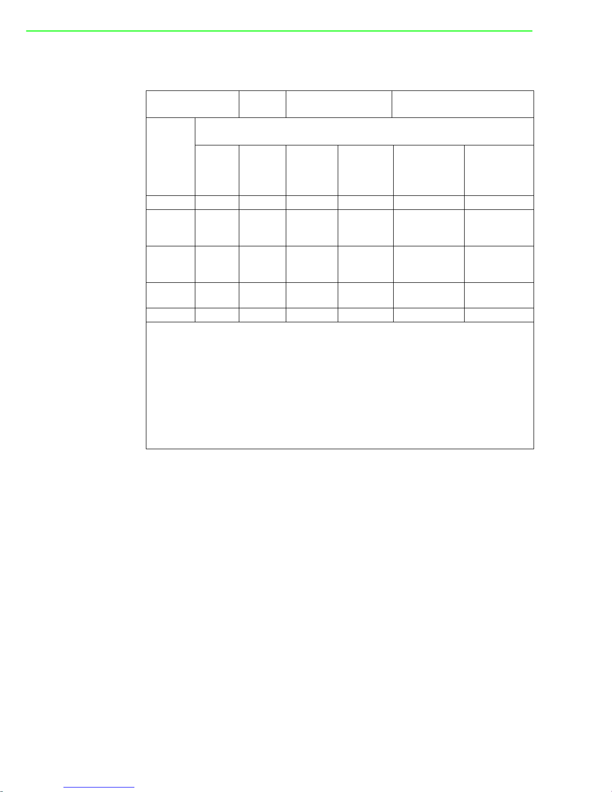
限用物質含有情況標示聲明書
設備名稱:
Equipment name
電腦
型號 (型式):
Type designation (Type)
UNO-1252G 系列
( 系列型號參見說明書 )
單元 Unit
限用物質及其化學符號
Restricted substances and its chemical symbols
鉛 Lead
(Pb)
汞
Mercury
(Hg)
鎘
Cadmium
(Cd)
六價鉻
Hexavalent
chromium
(Cr
+6
)
多溴聯苯
Polybrominated
biphenyls
(PBB)
多溴二苯醚
Polybrominated
diphenyl ethers
(PBDE)
電路板 - ○ ○ ○ ○ ○
機殼
( 外殼、支
架…等)
○○ ○ ○ ○ ○
其它固定
組件
(螺絲)
-○ ○ ○ ○ ○
配件
(線材)
○○ ○ ○ ○ ○
記憶卡 ○ ○ - ○ ○ ○
備考 1.“ 超出 0.1 wt %” 及 “ 超出 0.01 wt %” 係指限用物質之百分比含量超出百分比含
量基準值。
Note 1. “Exceeding 0.1 wt %” and “exceeding 0.01 wt %” indicate that the percentage content
of the restricted substance exceeds the reference percentage value of presence condition.
備考 2.“ ○ ” 係指該項限用物質之百分比含量未超出百分比含量基準值。
Note 2. “○”indicates that the percentage content of the restricted substance does not exceed
the percentage of reference value of presence.
備考 3.“ - ” 係指該項限用物質為排除項目。
Note 3. The “-” indicates that the restricted substance corresponds to the exemption.
Page 3

iii UNO-1252G User Manual
Copyright
The documentation and the software included with this product are copyrighted 2017
by Advantech Co., Ltd. All rights are reserved. Advantech Co., Ltd. reserves the right
to make improvements in the products described in this manual at any time without
notice. No part of this manual may be reproduced, copied, translated or transmitted
in any form or by any means without the prior written permission of Advantech Co.,
Ltd. Information provided in this manual is intended to be accurate and reliable. However, Advantech Co., Ltd. assumes no responsibility for its use, nor for any infringements of the rights of third parties, which may result from its use.
Acknowledgements
IBM, PC/AT, PS/2 and VGA are trademarks of International Business Machines Corporation.
Intel®, Core™, Atom™ and Quark™ are the trademarks of Intel Corporation
Yocto Project™ is a registered trademark of The Linux Foundation.
All other product names or trademarks are properties of their respective owners.
Support
For more information on this and other Advantech products, please visit our websites
at: http://www.advantech.com
For technical support and service, please visit our support website at:
http://support.advantech.com/
Part No. 2003W25202 Edition 3
Printed in Taiwan March 2017
Page 4
UNO-1252G User Manual iv
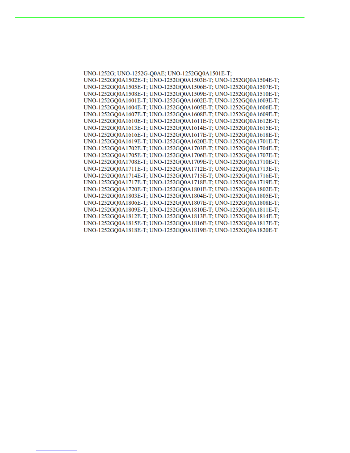
This manual applies to the below model which is abbreviated as UNO-1252G series
products in this article.
*Model number: UNO-1252G
*Part number:
Page 5

v UNO-1252G User Manual
Product Warranty (2 years)
Advantech warrants to you, the original purchaser, that each of its products will be
free from defects in materials and workmanship for two years from the date of purchase.
This warranty does not apply to any products which have been repaired or altered by
persons other than repair personnel authorized by Advantech, or which have been
subject to misuse, abuse, accident or improper installation. Advantech assumes no
liability under the terms of this warranty as a consequence of such events.
Because of Advantech’s high quality-control standards and rigorous testing, most of
our customers never need to use our repair service. If an Advantech product is defective, it will be repaired or replaced at no charge during the warranty period. For outof-warranty repairs, you will be billed according to the cost of replacement materials,
service time and freight. Please consult your dealer for more details.
If you think you have a defective product, follow these steps:
1. Collect all the information about the problem encountered. (For example, CPU
speed, Advantech products used, other hardware and software used, etc.) Note
anything abnormal and list any onscreen messages you get when the problem
occurs.
2. Call your dealer and describe the problem. Please have your manual, product,
and any helpful information readily available.
3. If your product is diagnosed as defective, obtain an RMA (return merchandize
authorization) number from your dealer. This allows us to process your return
more quickly.
4. Carefully pack the defective product, a fully-completed Repair and Replacement
Order Card and a photocopy proof of purchase date (such as your sales receipt)
in a shippable container. A product returned without proof of the purchase date
is not eligible for warranty service.
5. Write the RMA number visibly on the outside of the package and ship it prepaid
to your dealer.
Declaration of Conformity
CE
This product has passed the CE test for environmental specifications when shielded
cables are used for external wiring. We recommend the use of shielded cables. This
kind of cable is available from Advantech. Please contact your local supplier for
ordering information.
FCC Class A
Note: This equipment has been tested and found to comply with the limits for a Class
A digital device, pursuant to part 15 of the FCC Rules. These limits are designed to
provide reasonable protection against harmful interference when the equipment is
operated in a commercial environment. This equipment generates, uses, and can
radiate radio frequency energy and, if not installed and used in accordance with the
instruction manual, may cause harmful interference to radio communications. Operation of this equipment in a residential area is likely to cause harmful interference in
which case the user will be required to correct the interference at his own expense.
Page 6

UNO-1252G User Manual vi
Technical Support and Assistance
1. Visit the Advantech web site at www.advantech.com/support where you can find
the latest information about the product.
2. Contact your distributor, sales representative, or Advantech's customer service
center for technical support if you need additional assistance. Please have the
following information ready before you call:
– Product name and serial number
– Description of your peripheral attachments
– Description of your software (operating system, version, application software,
etc.)
– A complete description of the problem
– The exact wording of any error messages
Safety Precaution - Static Electricity
Follow these simple precautions to protect yourself from harm and the products from
damage.
To avoid electrical shock, always disconnect the power from your PC chassis
before you work on it. Don't touch any components on the CPU card or other
cards while the PC is on.
Disconnect power before making any configuration changes. The sudden rush
of power as you connect a jumper or install a card may damage sensitive electronic components.
Page 7

vii UNO-1252G User Manual
Safety Instructions
1. Read these safety instructions carefully.
2. Keep this User Manual for later reference.
3. Disconnect this equipment from any AC outlet before cleaning. Use a damp
cloth. Do not use liquid or spray detergents for cleaning.
4. For plug-in equipment, the power outlet socket must be located near the equip-
ment and must be easily accessible.
5. Keep this equipment away from humidity.
6. Put this equipment on a reliable surface during installation. Dropping it or letting
it fall may cause damage.
7. The openings on the enclosure are for air convection. Protect the equipment
from overheating. DO NOT COVER THE OPENINGS.
8. Make sure the voltage of the power source is correct before connecting the
equipment to the power outlet.
9. Position the power cord so that people cannot step on it. Do not place anything
over the power cord.
10. All cautions and warnings on the equipment should be noted.
11. If the equipment is not used for a long time, disconnect it from the power source
to avoid damage by transient overvoltage.
12. Never pour any liquid into an opening. This may cause fire or electrical shock.
13. Never open the equipment. For safety reasons, the equipment should be
opened only by qualified service personnel.
14. If one of the following situations arises, get the equipment checked by service
personnel:
– The power cord or plug is damaged.
– Liquid has penetrated into the equipment.
– The equipment has been exposed to moisture.
– The equipment does not work well, or you cannot get it to work according to
the user's manual.
– The equipment has been dropped and damaged.
– The equipment has obvious signs of breakage.
15. DO NOT LEAVE THIS EQUIPMENT IN AN ENVIRONMENT WHERE THE
STORAGE TEMPERATURE MAY GO BELOW -20° C (-4° F) OR ABOVE 60° C
(140° F) for UNO-1252G.THIS COULD DAMAGE THE EQUIPMENT. THE
EQUIPMENT SHOULD BE IN A CONTROLLED ENVIRONMENT.
16. CAUTION: DANGER OF EXPLOSION IF BATTERY IS INCORRECTLY
REPLACED. REPLACE ONLY WITH THE SAME OR EQUIVALENT TYPE
RECOMMENDED BY THE MANUFACTURER, DISCARD USED BATTERIES
ACCORDING TO THE MANUFACTURER'S INSTRUCTIONS.
17. ATTENTION: Danger d'explosion si la batterie est mal REMPLACE. REM-
PLACER UNIQUEMENT PAR LE MEME TYPE OU EQUIVALENT RECOMMANDÉ PAR LE FABRICANT, jeter les piles usagées SELON LES
INSTRUCTIONS DU FABRICANT.
18. The sound pressure level at the operator's position according to IEC 704-1:1982
is no more than 70 dB (A).
DISCLAIMER: This set of instructions is given according to IEC 704-1. Advantech
disclaims all responsibility for the accuracy of any statements contained herein.
警告使用者:這是甲類資訊產品,在居住的環境中使用時, 可能會造成射頻干擾,在
這種情況下,使用者會被要求採取某些適當對策。
Page 8

UNO-1252G User Manual viii
安全指示
1. 請仔細閱讀此安全操作說明。
2. 請妥善保存此用戶手冊供日後參考。
3. 用濕抹布清洗設備前,請從插座拔下電源線。請不要使用液體或去汙噴霧劑清洗
設備。
4. 對於使用電源線的設備,設備周圍必須有容易接觸到的電源插座。
5. 請不要在潮濕環境中使用設備。
6. 請在安裝前確保設備放置在可靠的平面上,意外跌落可能會導致設備損壞。
7. 設備外殼的開口是用於空氣對流,從而防止設備過熱。請勿覆蓋開孔。
8. 當您連接設備到電源插座上前,請確認電源插座的電壓是否符合要求。
9. 請將電源線佈置在人們不易絆到的位置,並不要在電源線上覆蓋任何雜物。
10. 請注意設備上的所有警告和注意標語。
11. 如果長時間不使用設備,請將其同電源插座斷開,避免設備被超標的電壓波動損
壞。
12. 請不要讓任何液體流入通風口,以免引起火災或者短路。
13. 請不要自行打開設備。為了確保您的安全,請由經過認證的工程師來打開設備。
14. 如遇下列情況,請由專業人員來維修:
電源線或者插頭損壞;
設備內部有液體流入;
設備曾暴露在過於潮濕的環境中使用;
設備無法正常工作,或您無法通過用戶手冊來使其正常工作;
設備跌落或者損壞;
設備有明顯的外觀破損。
15. 請不要把設備放置在超出我們建議的溫度範圍的環境,即不要低於 0°C
(32°F)或高於 40°C (104°F),否則可能會損壞設備。
16. 注意:若電池放置不正確,將有爆炸的危險。因此,只可以使用製造商推薦的同
一種或者同等型號的電池進行替換。請按照製造商的指示處理舊電池。
17. 根據 IEC 704-1:1982 的規定,操作員所在位置的聲壓級不可高於 70dB(A)。
18. 限制區域:請勿將設備安裝於限制區域使用。
19. 免責聲明:該安全指示符合 IEC 704-1 的要求。研華公司對其內容的準確性不承
擔任何法律責任。
Page 9

ix UNO-1252G User Manual
Contents
Chapter 1 Overview...............................................1
1.1 Introduction ............................................................................................... 2
1.2 Safety Precautions .................................................................................... 2
1.3 Accessories............................................................................................... 3
Chapter 2 Hardware Functionality.......................5
2.1 Introduction ............................................................................................... 6
Figure 2.1 Front Panel of UNO-1252G ........................................ 6
Figure 2.2 Top Panel of UNO-1252G .......................................... 6
Figure 2.3 Bottom Panel of UNO-1252G ..................................... 6
2.2 Isolated Serial Interface (COM1~COM2) .................................................. 7
2.2.1 Isolated RS-232/485 Interface (COM1) ........................................ 7
2.2.2 Isolated RS-232 Interface (COM2) .............................................. 7
2.3 Ethernet LAN Connector........................................................................... 7
2.4 Power Connector ...................................................................................... 7
2.5 USB Connector ......................................................................................... 7
2.6 Digital Input/Output Interface .................................................................... 8
Figure 2.4 Wet Contact Connection............................................. 8
Figure 2.5 Wet Contact Connection............................................. 8
2.7 LED Indicators........................................................................................... 9
2.8 microSD card Slot ..................................................................................... 9
2.9 SIM card Slot............................................................................................. 9
2.10 PCI Express Mini Card Socket................................................................. 9
Figure 2.6 PCI Express Mini Card Socket on board .................... 9
2.11 iDoor Expansion I/O................................................................................ 10
2.12 Antenna Mounting................................................................................... 10
2.13 RTC Battery Specification...................................................................... 10
2.14 Power Management................................................................................ 10
2.15 Reset Button ........................................................................................... 10
Chapter 3 Initial Setup ........................................11
3.1 Chassis Grounding.................................................................................. 12
Figure 3.1 Chassis Grounding Connection................................ 12
3.2 Inserting a SD card/SIM card.................................................................. 12
3.3 Installing a Wireless module Card and Antenna (Optional) .................... 13
3.4 3.4 Installing iDoor expansion I/O ........................................................... 14
3.5 Din-rail Kit Assembly ............................................................................... 14
Figure 3.2 UNO-1252G with Din-rail mounting .......................... 14
3.6 Connecting Power................................................................................... 15
Chapter 4 Software Functionality......................17
4.1 Console Port Setting ............................................................................... 18
Figure 4.1 PuTTY Configuration ................................................ 18
Figure 4.2 Log in to UNO-1252G............................................... 18
4.2 LAN A Connection................................................................................... 19
Figure 4.3 Enable LAN A functionality ....................................... 19
Figure 4.4 LAN A connection status .......................................... 19
Figure 4.5 LAN A IP Address..................................................... 20
4.3 LAN B Connection................................................................................... 20
Figure 4.6 Enable LAN B functionality ....................................... 20
Figure 4.7 LAN B connection status .......................................... 21
Page 10

UNO-1252G User Manual x
Figure 4.8 LAN B IP Address .................................................... 21
4.4 Assign IP Address for LAN Port.............................................................. 22
Figure 4.9 Assigning an IP Address example........................... 22
4.5 Digital Input & Output.............................................................................. 22
4.5.1 Setting of Digital Output.............................................................. 22
4.5.2 Checking of Digital Input............................................................. 23
Appendix A System Settings and Pin Assignments
25
A.1 Board Connectors and Switches............................................................. 26
Figure A.1 Connector & Switch Locations (front))...................... 26
Table A.1: Connectors and Jumpers ......................................... 26
A.2 Isolated RS-232/485 Serial Port (COM1)................................................ 26
Table A.2: RS-232/485 Serial Port Pin Assignments................. 26
Table A.3: Jumper for COM1 RS-232/485 switch...................... 27
A.3 Isolated RS-232 Standard Serial Port (COM2)....................................... 27
Table A.4: RS-232 Serial Port PIN Assignment......................... 27
A.4 USB Connector....................................................................................... 28
Table A.5: USB 2.0 Connector Pin Assignments....................... 28
A.5 LAN Connector ....................................................................................... 28
Table A.6: LAN Connector Pin Assignments ............................. 28
A.6 Isolated Digital I/O Connector ................................................................. 29
Table A.7: Isolated Digital I/O Connector .................................. 29
A.7 Power Connector (PWR) ........................................................................ 29
Table A.8: Power connector pin assignments ........................... 29
Page 11

Chapter 1
1 Overview
This chapter provides an overview
of UNO-1252G specifications.
Sections include:
Introduction
Hardware specification
Safety precautions
Page 12
UNO-1252G User Manual 2
1.1 Introduction
The UNO-1252G is an embedded Application Ready Platform (ARP) that can
shorten your development time and offers a wide array of networking interfaces to
fulfill the extensive needs in different projects. UNO-1252G employs Intel’s latest
Quark technology and provides rich interfaces including up to 2 x isolated serial port,
2 x LAN, 2 x USB ports, 8 x isolated DI/O and 1 x iDoor I/O expansion. UNO-1252G
supports wireless PCI Express Mini Card (mPCIe card) and Advantech latest iDoor
technology for various Internet of Things (IoT) applications.
The UNO-1252G can operate in wide temperatures (from -20 to 60°C). The UNO1252G also adopts Intel Quark CPUs with great power efficiency for gateway plat-
forms.
The UNO-1252G provides multiple expansion including two mPCIe cards, one
microSD and SIM card support. With these expansions the UNO-1252G has great
expandability from Wi-Fi, 3G, I/O expansion and industrial fieldbus protocols by iDoor
technology.
The UNO-1252G with Intel Quark CPUs supports Yocto Linux which is an open
embedded OS system allowing users to integrate applications easily by taking the
form of Board Support Package (BSP) layers for which a standard format has been
developed. That can provide versatile functions to fulfill diverse requirements.
1.2 Safety Precautions
The following sections tell how to make each connection. In most cases, you will simply need to connect a standard cable.
Warning! Always disconnect the power cord from your chassis whenever you are
working on it. Do not connect while the power is on. A sudden rush of
power can damage sensitive electronic components. Only experienced
electronics personnel should open the chassis.
Warning! Toujours à la terre pour éliminer toute charge d'électricité statique avant
toucher UNO-1252G. Appareils électroniques modernes sont très sensibles à charges d'électricité statique. Utilisez un bracelet antistatique à
tout moment. Placez tous composants électroniques sur une surface
antistatique ou dans un statique-sac blindé.
Caution! Always ground yourself to remove any static electric charge before
touching the product. Modern electronic devices are very sensitive to
static electric charges. Use a grounding wrist strap at all times. Place all
electronic components on a static-dissipative surface or in an anti-static
bag.
Caution! Toujours débrancher le cordon d'alimentation de votre boîtier lorsque
vous êtes travailler. Ne branchez pas lorsque l'appareil est allumé. Un
afflux soudain de puissance peut endommager les composants électroniques sensibles. Seulement connu personnel de l'électronique
devraient ouvrir le châssis.
Page 13

3 UNO-1252G User Manual
Chapter 1 Overview
1.3 Accessories
Please refer below for the accessory list:
3-pin phoenix connector for power wiring (Advantech P/N: 1652003206)
8-pin phoenix connector for Digital I/O wiring (Advantech P/N: 1652005896)
Din-Rail Mounting kit (Advantech P/N: 1960018849T021 )
3 x screws for Din-Rail kit (Advantech P/N: 1930000686)
2 x screws for mPCIe card (Advantech P/N: 1935020300)
Warranty card
If anything is missing or damaged, contact your distributor or sales representative
immediately.
Page 14

UNO-1252G User Manual 4
Page 15

Chapter 2
2 Hardware
Functionality
This chapter shows how to setup
the UNO-1252G’s hardware functions, including connecting
peripherals, setting switches and
indicators.
Sections include:
Introduction
Isolated RS-232/485 Interface
Isolated RS-232 Interface
Ethernet LAN Connector
Power Con nector
USB Co nnector
Isolated Digital Input/Output
LED Indicators
microSD card Slot
SIM card Slot
PCI Express Mini Card Socket
iDoor Expansion I/O
Antenna Mounting
RTC Battery Specification
Power Management
Reset Button
Page 16

UNO-1252G User Manual 6
2.1 Introduction
The following figures show the panel configuration on UNO-1252G. More information
of each peripheral is included in the following sections.
Figure 2.1 Front Panel of UNO-1252G
Figure 2.2 Top Panel of UNO-1252G
Figure 2.3 Bottom Panel of UNO-1252G
Page 17

7 UNO-1252G User Manual
Chapter 2 Hardware Functionality
2.2 Isolated Serial Interface (COM1~COM2)
UNO-1252G offers standard isolated RS-232/485 (COM1), one isolated RS-232
(COM2) serial communication interface ports:
Isolation Protection 1,000 VDC
Overvoltage Protection 30 VDC
2.2.1 Isolated RS-232/485 Interface (COM1)
The UNO-1252G offers one isolated RS-232/485 serial communication interface
ports as COM1. The default COM port mode is RS-485. User can switch either to
RS-232 or RS-485 mode by setting the switch. The terminal resistance for long distance signal transmission in RS-485 mode is also set by the switch.
Refer to Appendix A.2 for their pin assignments and switch setting.
2.2.2 Isolated RS-232 Interface (COM2)
The UNO-1252G offers one standard isolated RS-232 serial communication interface
ports as COM2. The COM2 is designed as console port for user's configuration.
Refer to Appendix A.3 for their pin assignments.
2.3 Ethernet LAN Connector
The UNO-1252G is equipped with two 10/100MB LAN controllers. The controller
employed Texas Instrument DP83848K Ethernet chipset that is fully compliant with
IEEE 802.3u 10/100Base-T CSMA/CD standards. The Ethernet port provides a standard RJ-45 jack on board, and LED indicators on the front side to show its Link
(Orange LED) and Active (Green LED) status.
2.4 Power Connector
The UNO-1252G comes with a Phoenix connector that carries 10~36 VDC external
power input, and features reversed wiring protection. Therefore, it will not cause any
damage to the system by reversed wiring of ground line or power line. Refer to
Appendix A.7
2.5 USB Connector
The UNO-1252G provides one USB2.0 host and one USB device connectors. The
USB interface supports Plug and Play, which enables user to connect or disconnect a
device without turning off the computer. The USB host port is EHCI Rev. 2.0 compliant also provides hot swapping for up to 127 external devices. Refer to Appendix A.5
for their pin assignment.
Page 18

UNO-1252G User Manual 8
2.6 Digital Input/Output Interface
There are four digital inputs and four digital outputs configured from GPIO pins for
most of on/off trigger and status reading.
Digital Input
Input Channels 4
Input Voltage (Wet Contact)
– Logic 0: 0~3 VDC
– Logic 1: 10~30 VDC
Input Current
– 10 VDC @ 2.67mA
– 20 VDC @ 5.64mA
– 30 VDC @ 8.91mA
Isolation Protection 1,000 VDC
Overvoltage Protection 30 VDC
Figure 2.4 Wet Contact Connection
Digital Output
Output Channels 4
Output Voltage: 5~30 VDC
Output Capability Sink: Max. 24 mA per channel
Open Collector to 30 V
Figure 2.5 Wet Contact Connection
Page 19

9 UNO-1252G User Manual
Chapter 2 Hardware Functionality
2.7 LED Indicators
There are eight LEDs indicating the status of the system power, RTC battery, SD
card, LAN port transmit/receive and PL1~3 for user’s configurations.
PWR: Green light means normal, orange light means standby.
BTR: Red means RTC battery being abnormal, please check the RTC battery.
Tx/Rx 1~2: Flashing green means COM 1 and COM2 signals are being trans-
mitted and received.
SD: Flashing green means the microSD card is being writing and reading.
PL 1~3: User can configure the LED indicators’ behavior through GPIO control.
2.8 microSD card Slot
There is one microSD slot on board for standard microSD card storage. User can
insert microSD card from the bottom panel shown in Figure 2.3.
2.9 SIM card Slot
There is one Mini-SIM card slot on board for standard Mini-SIM card (2FF) usage.
User can insert standard Mini-SIM card from the bottom panel shown in Figure 2.3.
2.10 PCI Express Mini Card Socket
The UNO-1252G supports two full-size PCI Express Mini (mPCIe) card expansion,
refer to Figure 2.5. The first interface (CN5) provides PCI Express (PCIe) signal, and
the second interface (CN3) provides USB signal and connecting with SIM card slot.
The mPCIe expansion are mainly targeted to support iDoor technology/module for
diversified applications. Users can install iDoor module easily from the iDoor expansion I/O on the front panel shown in Figure 2.1.
Figure 2.6 PCI Express Mini Card Socket on board
Page 20

UNO-1252G User Manual 10
2.11 iDoor Expansion I/O
There is an iDoor Expansion I/O on the front panel shown in Figure 2.1 that allows
user to install iDoor modules with extra I/O for specific applications. For more iDoor
product information, please visit Advantech’s website. http://www.advantech.com
2.12 Antenna Mounting
The UNO-1252G provides two antenna mounting holes with pre-cut cover that allows
users to install antenna kit for Wi-Fi, GPRS/3G or other wireless functions. The two
antenna mounting holes are on the top panel shown in Figure 2.2.
2.13 RTC Battery Specification
The RTC Battery is used to reserve the setting in BIOS and system clock when the
power is disconnected for a short time.
Type: BR2032 W/C
Output Voltage: 3 VDC
Location: On board
2.14 Power Management
The UNO-1252G supports AT-type for system booting up. The system will automatically boot up once the power is connected.
2.15 Reset Button
Press the “RST” button to activate the hardware reset function. The system reset button is on the top panel shown in Figure 2.2.
Page 21

Chapter 3
3 Initial Setup
This chapter introduces how to
initialize the UNO-1252G.
Sections include:
Chassis Ground ing
Inserting a microSD/SIM card
Installing a wireless module
card and antenna
Installing iDoor expansion I/O
Din -rail kit assembly
Conneting Power
Page 22

UNO-1252G User Manual 12
3.1 Chassis Grounding
The UNO-1252G is designed with EMI protection and a stable grounding base. There
is an easy-to-connect chassis grounding point to use. Note that the system ground
and chassis ground are separate.
Figure 3.1 Chassis Grounding Connection
3.2 Inserting a SD card/SIM card
The UNO-1252G provides one microSD card slot and one Mini-SIM card slot. Users
can insert the cards using the following steps.
1. Remove the power cord.
2. Unscrew the microSD/SIM card lid on the bottom panel.
3. Insert the microSD card or Mini-SIM card into the slots.
4. Screw the lid back.
Page 23

13 UNO-1252G User Manual
Chapter 3 Initial Setup
3.3 Installing a Wireless module Card and Antenna
(Optional)
For optional wireless module card and antenna, please contact Advantech for the following wireless solution kit.
Top panel with pre-cut antenna holes
The internal coaxial cable with standard SMA connector
For more information about internal coaxial cable, please contact with Advantech.
Wireless module card (PCI Express Mini card)
The UNO-1252G supports two full-size mPCIe slots for wireless module card installation, please refer to Session 2.10. For more information about wireless module cards,
contact Advantech.
Page 24

UNO-1252G User Manual 14
Antenna
Select the necessary specification according to your application. For more information about antenna, please contact with Advantech.
Then follow the below steps for the installation:
1. Unscrew the chassis and open it.
2. Remove the pre-cut cover on antenna hole(s) on the top panel for antenna
installation.
3. Install the internal coaxial cable(s) through the antenna hole(s).
4. Insert the wireless module card into the PCI Express mini card socket and
screw it.
5. Connect the internal coaxial cable(s) with the wireless module card.
6. Screw back the chassis.
7. Assemble the antenna(s) on the SMA connector.
3.4 3.4 Installing iDoor expansion I/O
The UNO-1252G supports one iDoor expansion I/O on the front panel shown in Figure 2.1. For the iDoor installation, please refer to the documentary from iDoor product
package.
3.5 Din-rail Kit Assembly
The UNO-1252G supports Din-rail mounting. The Din-rail kit and screws are included
in the accessory bag. The assembly instruction is shown in Figure 3.2 below.
Figure 3.2 UNO-1252G with Din-rail mounting
Page 25

15 UNO-1252G User Manual
Chapter 3 Initial Setup
3.6 Connecting Power
Connect the UNO-1252G to a 10~36 VDC power source. The power source can
either be from a listed power adapter or DC power source.
Page 26

UNO-1252G User Manual 16
Page 27

Chapter 4
4 Software Functionality
This chapter details the software
operating on UNO-1252G.
Sections include:
Setting Console Port
Co nnection
Assigning IP Addresses
Digital Input and Output
Page 28

UNO-1252G User Manual 18
4.1 Console Port Setting
The UNO-1252G can communicate with a host server (Windows or Linux) by using
serial cables. Common serial communication programs such as HyperTerminal, Tera
Term or PuTTY can be used in this case. The example as below describes the serial
terminal setup using PuTTY on a Windows host:
1. Connect RS-232 console port (COM2) on the UNO-1252G to the host computer
by using a serial cable.
2. Open PuTTY on the host computer, and select the settings as shown in Figure
4.1.
Figure 4.1 PuTTY Configuration
3. Power on UNO-1252G. Boot will take a while, after which the login screen
appears. Log in with: root as shown in Figure 4.2.
Figure 4.2 Log in to UNO-1252G
Page 29

19 UNO-1252G User Manual
Chapter 4 Software Functionality
4.2 LAN A Connection
Make sure the DHCP service works in the connected LAN.
Remove network connection from both of the two LAN ports.
# ifconfig enp0s20f7 down
# ifconfig enp0s20f6 up
# ifconfig
Figure 4.3 Enable LAN A functionality
Plug the network cable into the LAN A port and wait for the " enp0s20f6: link
becomes ready" showing up.
Figure 4.4 LAN A connection status
Checking if there is an IP or not.
# ifconfig
Page 30

UNO-1252G User Manual 20
Figure 4.5 LAN A IP Address
4.3 LAN B Connection
Make sure the DHCP service works in the connected LAN.
Remove network connection from both of the two LAN ports.
# ifconfig enp0s20f6 down
# ifconfig enp0s20f7 up
# ifconfig
Figure 4.6 Enable LAN B functionality
Page 31

21 UNO-1252G User Manual
Chapter 4 Software Functionality
Plug the network cable into the LAN B port and wait for the " enp0s20f7: link
becomes ready" showing up.
Figure 4.7 LAN B connection status
Checking if there is an IP or not.
# ifconfig
Figure 4.8 LAN B IP Address
Page 32

UNO-1252G User Manual 22
4.4 Assign IP Address for LAN Port
Manually Assign IP Address for LAN port with below command.
# ifconfig enp0s20f6 XXX.XX.X.X
# ifconfig enp0s20f7 XXX.XXX.X.X
XXX.XXX.X.X is the IP address which is wanted to be assigned.
Figure 4.9 Assigning an IP Address example
4.5 Digital Input & Output
4.5.1 SettingofDigitalOutput
SetsignaltobeLow
#echo0>/sys/class/gpio/*/value
SetsignaltobeHigh
#echo1>/sys/class/gpio/*/value
“*”couldbefilledinoneofbelowgpioname:
gpio0 <‐‐>DO2
gpio1 <‐‐>DO3
gpio3 <‐‐>PL2
gpio4 <‐‐>PL3
gpio8 <‐‐>PL1
gpio10 <‐‐> DO0
gpio12 <‐‐> DO1
Page 33

23 UNO-1252G User Manual
Chapter 4 Software Functionality
4.5.2 CheckingofDigitalInput
Observethevalueofdigitalinput
#cat/sys/class/gpio/*/value
“*”couldbefilledinoneofbelowgpioname:
gpio11<‐‐>DI0
gpio13<‐‐>DI1
gpio14<‐‐>DI2
gpio15<‐‐>DI3
Page 34

UNO-1252G User Manual 24
Page 35

Appendix A
A System Settings and
Pin Assignments
Page 36

UNO-1252G User Manual 26
A.1 Board Connectors and Switches
There are several connectors and jumpers on the UNO-1252G board. The following
sections tell you how to configure the UNO-1252G hardware setting.
Figure A.1 shows the locations of UNO-1252G’s connectors and switches.
Figure A.1 Connector & Switch Locations (front))
A.2 Isolated RS-232/485 Serial Port (COM1)
Table A.1: Connectors and Jumpers
Label Function
CN3 mPCIe slot with USB & SIM signal
CN5 mPCIe slot with PCIe signal
CN6 microSD card slot
CN4 SIM card slot for CN3
SW8 Switch for COM1 RS-232/485, terminal resistance for RS-485
Table A.2: RS-232/485 Serial Port Pin Assignments
Pin Pin Name RS-485
1DCDData2RxDData+
3TxDNC
4DTRNC
5GNDGND
6DSRNC
7RTSNC
8CTSNC
9 RI NC
15
9
6
324
78
Page 37

27 UNO-1252G User Manual
Appendix A System Settings and Pin Assignments
The terminal resistance is recommended to be used for long distance signal transmission in RS-485 mode.
A.3 Isolated RS-232 Standard Serial Port (COM2)
Table A.3: Jumper for COM1 RS-232/485 switch
Mode RS-232 RS-485 with terminal
resistance
RS-485 without
terminal resistance
Switch (SW8)
Setting
Table A.4: RS-232 Serial Port PIN Assignment
Pin Pin Name
1 DCD
2RxD
3TxD
4DTR
5GND
6DSR
7RTS
8CTS
9 RI
15
9
6
324
78
Page 38

UNO-1252G User Manual 28
A.4 USB Connector
A.5 LAN Connector
Table A.5: USB 2.0 Connector Pin Assignments
Pin Signal Name Cable Color
1 VCC Red
2 DATA- White
3 DATA+ Green
4 GND Black
Table A.6: LAN Connector Pin Assignments
Pin 10/100Base-T Name
1XMT+
2XMT3RCV+
4NC
5NC
6RCV7NC
8NC
Page 39

29 UNO-1252G User Manual
Appendix A System Settings and Pin Assignments
A.6 Isolated Digital I/O Connector
A.7 Power Connector (PWR)
Table A.7: Isolated Digital I/O Connector
Description PIN PIN Description
ECOM PIN1 PIN2 PCOM
DI3 PIN3 PIN4 DO3
DI2 PIN5 PIN6 DO2
DI1 PIN7 PIN8 DO1
DI0 PIN9 PIN10 DO0
Table A.8: Power connector pin assignments
Pin Description
1 10~36 V+
DC
Input 1
2 10~36 V-
DC
Input 2
3 Field Ground
Page 40

www.advantech.com
Please verify specifications before quoting. This guide is intended for reference
purposes only.
All product specifications are subject to change without notice.
No part of this publication may be reproduced in any form or by any means,
electronic, photocopying, recording or otherwise, without prior written permission of the publisher.
All brand and product names are trademarks or registered trademarks of their
respective companies.
© Advantech Co., Ltd. 2017
 Loading...