

Page 1

User Manual
TREK-734
Computer
Page 2

TREK-734 User Manual
2
Copyright
The documentation and the software included with this product are copyrighted 2017
by Advantech Co., Ltd. All rights are reserved. Advantech Co., Ltd. reserves the right
to make improvements in the products described in this manual at any time without
notice. No part of this manual may be reproduced, copied, translated or transmitted
in any form or by any means without the prior written permission of Advantech Co.,
Ltd. Information provided in this manual is intended to be accurate and reliable. However, Advantech Co., Ltd. assumes no responsibility for its use, nor for any infringements of the rights of third parties, which may result from its use.
Acknowledgements
i.MX6 is trademarks of Freescale NXP.
Android is registered trademarks of Google LLC.
All other product names or trademarks are properties of their respective owners.
Product Warranty (2 years)
Advantech warrants to you, the original purchaser, that each of its products will be
free from defects in materials and workmanship for two years from the date of purchase.
This warranty does not apply to any products which have been repaired or altered by
persons other than repair personnel authorized by Advantech, or which have been
subject to misuse, abuse, accident or improper installation. Advantech assumes no
liability under the terms of this warranty as a consequence of such events.
Because of Advantech’s high quality-control standards and rigorous testing, most of
our customers never need to use our repair service. If an Advantech product is defective, it will be repaired or replaced at no charge during the warranty period. For outof-warranty repairs, you will be billed according to the cost of replacement materials,
service time and freight. Please consult your dealer for more details.
If you think you have a defective product, follow these steps:
1. Collect all the information about the problem encountered. (For example, CPU
speed, Advantech products used, other hardware and software used, etc.) Note
anything abnormal and list any onscreen messages you get when the problem
occurs.
2. Call your dealer and describe the problem. Please have your manual, product,
and any helpful information readily available.
3. If your product is diagnosed as defective, obtain an RMA (return merchandize
authorization) number from your dealer. This allows us to process your return
more quickly.
4. Carefully pack the defective product, a
Order Card and a photocopy proof of purchase date (such as your sales receipt)
in a shippable container. A product returned without proof of the purchase date
is not eligible for warranty service.
5. Write the RMA number visibly on the outside of the package and ship it prepaid
to your dealer.
Part No. Edition 1
Jan 2018
fully-completed
Repair and Replacement
Page 3

3
TREK-734 User Manual
Declaration of Conformity
CE
This product has passed the CE test for environmental specifications. Test conditions
for passing included the equipment being operated within an industrial enclosure. In
order to protect the product from being damaged by ESD (Electrostatic Discharge)
and EMI leakage, we strongly recommend the use of CE-compliant industrial enclo-
„
FCC Caution :
Any changes or modifications not expressly approved by the party responsible for
FCC RF Radiation Exposure Statement :
This device meets the government`s requirements for exposure to radio waves.
This device is designed and manufactured not to exceed the emission limits for
.
sure products.
FCC Class B
Note: This equipment has been tested and found to comply with the limits for a Class
B digital device, pursuant to part 15 of the FCC Rules. These limits are designed to
provide reasonable protection against harmful interference in a residential installation. This equipment generates, uses and can radiate radio frequency energy and, if
not installed and used in accordance with the instructions, may cause harmful interference to radio communicati ons. However, there is no guarantee that interference
will not occur in a particular installation. If this equipment does cause harmful interference to radio or television reception, which can be determined by turning the equipment off and on, the user is encouraged to try to correct the interference by one or
more of the following measures:
Reorient or relocate the receiving antenna
Increase the separation between the equipment and receiver.
Connect the equipment into an outlet on a circuit different from that to which the
receiver is connected.
Consult the dealer or an experienced radio/TV technician for help.
This device complies with Part 15 FCC Rules.
Operation is subject to the following two conditions.
(1) This device may not cause harmful interference , and
(2) The device must accept any interference received, including
interference may cause undesired operation.
compliance could void the user's authority to operate this equipment.
exposure to radio frequency(RF) energy set by the Federal Communications
Commission of the U.S. Government.
This device complies with FCC radiation exposure limits set forth for an uncontrolled
environment. In order to avoid the possibility of exceeding the FCC radio frequency
exposure limits, human proximity to the antenna shall not be less than 20cm (8
inches) during normal operation.
Changes or modifications not expressly approved by the party responsible for
compliance could void the user`s authority to operate the equipment.
Page 4

TREK-734 User Manual
4
Technical Support and Assistance
1. Visit the Advantech web site at
the latest information about the product.
2. Contact your distributor, sales representative, or Advantech's customer service
center for technical support if you need additional assistance. Please have the
following information ready before you call:
– Product name and serial number
– Description of your peripheral attachments
– Description of your software (operating system, version, application software,
etc.)
– A complete description of the problem
– The exact wording of any error messages
http://support.advantech.com
where you can find
Page 5
5
TREK-734 User Manual
Part number
Description
Q`ty
TREK-734C
TREK-734 Computer
1
1700019031
Power cable (2M)
1
Warnings, Cautions and Notes
Warning! Warnings indicate conditions, which if not observed, can cause personal
injury!
Caution! Cautions are included to help you avoid damaging hardware or losing
data. e.g.
There is a danger of a new battery exploding if it is incorrectly installed.
Do not attempt to recharge, force open, or heat the battery. Replace the
battery only with the same or equivalent type recommended by the manufacturer. Discard used batteries according to the manufacturer's
Note! Notes provide optional additional information.
instructions.
Document Feedback
To assist us in making improvements to this manual, we would welcome comments
and constructive criticism. Please send all such - in writing to: support@advantech.com
Packing List
Before setting up the system, check that the items listed below are included and in
good condition. If any item does not accord with the table, please contact your dealer
immediately.
Page 6

TREK-734 User Manual
6
Ordering Information
P/N Description
TREK-734C-WBADA0E TREK-734 I. MX6 1GB,4GB , Android5.1 WiFi only
Safety Instructions
1. Read these safety instructions carefully.
2. Keep this User Manual for later reference.
3. Disconnect this equipment from any AC outlet before cleaning. Use a damp
cloth. Do not use liquid or spray detergents for cleaning.
4. For plug-in equipment, the power outlet socket must be located near the equip-
ment and must be easily accessible.
5. Keep this equipment away from humidity.
6. Put this equipment on a reliable surface during installation. Dropping it or
fall may cause damage.
it
7. Do not leave this equipment in an environment unconditioned where the storage
temperature under -30° C (-22° F) or above 80° C (176° F), it may damage the
equipment. Operating temperature: -20°C~70°C without battery.
8. Do not operate this equipment in an environment temperature may over
70°C(158° F). The surface temperature of plastic chassis may be hot.
9. Make sure the voltage of the power source is correct before connecting the
equipment to the power outlet.
10. Position the power cord so that people cannot step on it. Do not place anything
over the power cord. The voltage and current rating of the cord should be greater
than the voltage and current rating marked on the product.
11. All cautions and warnings on the equipment should be noted.
12. If the equipment is not used for a long time, disconnect it from the power source
to avoid damage by transient overvoltage.
13. Never pour any liquid into an opening. This may cause fire or electrical shock.
14. Never open the equipment. For safety reasons, the equipment should be
opened only by qualified service personnel.
15. If one of the following situations arises, get the equipment checked by service
personnel:
„
The power cord or plug is damaged.
„
Liquid has penetrated into the equipment.
„
The equipment has been exposed to moisture.
„
The equipment does not work well, or you cannot get it to work according to
the user's manual.
„
The equipment has been dropped and damaged.
„
The equipment has obvious signs of breakage.
16. CAUTION: The computer is provided with a battery-powered real-time clock cir-
cuit. There is a danger of explosion if battery is incorrectly replaced. Replace
letting
Page 7

only with same or equivalent type recommended by the
manufacture. Discard used batteries according to the
manufacturers instructions.
17. This device complies with Part 15 of the FCC rules. Operation is
subject to the following two conditions:
(1) this device may not cause harmful interference, and
(2) this device must accept any interference received, including
interference that may cause undesired operation.
18. CAUTION: Always completely disconnect the power cord from
your chassis whenever you work with the hardware. Do not
make connections while the power is on. Sensitive electronic
components can be damaged by sudden power surges.
19. CAUTION: Always ground yourself to remove any static charge
before touching the motherboard, backplane, or add-on cards.
Modern electronic devices are very sensitive to static electric
charges. As a safety precaution, use a grounding wrist strap at all
times. Place all electronic components on a static-dissipative
surface or in a static-shielded bag when they are not in the chassis.
20. CAUTION: Any unverified component could cause unexpected
damage. To ensure the correct installation, please always use the
components (ex. screws) provided with the accessory box.
Safety Precaution - Static Electricity
Follow these simple precautions to protect yourself from harm and the products from
damage.
„
To avoid electrical shock, always disconnect the power from your PC chassis
before you work on it. Don't touch any components on the mainboard or other
cards while the system is on.
„
Disconnect power before making any configuration changes. The sudden rush
of power as you connect a jumper or install a card may damage sensitive electronic components.
This product is intended to be supplied by a Listed DC power source, rated
9~32Vdc, 10A maximum and Tma 55 degree C, if need further assistance with
purchasing the DC power source, please contact Advantech for further information.
Warning! 1. Input voltage rated: 9 - 32 Vdc.
2. Transport: carry the unit with both hands and handle with care.
3. Maintenance: to properly maintain and clean the surfaces, use only
approved products or clean with a dry applicator.
4. SD/SIM card: Turn off the power before inserting or removing
the storage cards.
Page 8

TREK-734 User Manual
8
Chapter
1
General Information ..............................1
1.2
General
Specifications .................................................................................
3
1.3
Dimensions
..................................................................................................
5
Figure 1.1 TREK-734
dimensions...................................................
5
Chapter
2
System
Setup
.........................................7
Chapter
3
I/O connectors Pin assignments…….14
I/O Connectors Pin Assignment………………….……………………………..15
3.3.4 Mini USB Connector (Rear side)………………………………….……..17
Chapter
4
Software Demo Utility Setup………....18
4.1
MRM SDK Package Contents & Overview..…….……………………..….…..18
19
Contents
1.1 Introduction
2.1
2.2
..................................................................................................
A Quick Tour of the TREK-734 Computer……..
Figure 2.1 Front view of
Figure 2.2 Rear view of
Installation Procedures…………………………………………………….……8
2.2.1 Connect Power ………………………………
Figure 2.3 Power connector
Table 2.2: Pin
Figure 2.4 Power connector photo
Definition
TREK-734 ...............................................
TREK-734 ................................................
outlook ...............................................
of
Power Connector................................
..........................................
.......................................9
................................................
10
10
2
8
8
8
9
3.1
4.2
4.3
4.4
4.5
3.3.1 Power Connector………………………….………………………………15
3.3.2 HDC Connector……………………….…………………………………..15
3.3.3 USB Connector…………………..………………………………………..16
How MRM SDK works……………………………………………………………
Installation of the MRM SDK…………………………………………………….20
Install Prebuilt Sample Apps…………………………………………………….21
IVCP Demonstration………………………..……………………………………22
5.5.1 Firmware…………………..………………………………………………..23
5.5.2 Power Management……………..………………………………….……..24
5.5.3 Battery………………………………………………………………………25
5.5.4 Alarm………………………………………………………………………..26
5.5.5 Watchdog…………………………………………………………………..27
5.5.6 Digital IO……………………………………………………………………28
5.5.7 Peripheral Control…………………………………………………………29
5.5.8 Storage……………………………………………………………………..30
5.5.9 G Sensor…………………………………………………………………..30
5.5.10 G Sensor Alarm………………………………………………………….31
5.5.11 P Sensor………………………………………………………………….32
5.5.12 Hotkey…………………………………………………………………….33
Page 9

4.6
VCIL Demonstration………………….………………………………………..34
Appendix
A
Peripheral Installation…………………......…….53
Installing the RAM mount kit……………………………………………………55
Installing the IP54 I/O cover…………………………………………………….56
4.7
5.6.1 CAN…………………………………………………………………………35
5.6.2 CAN Filter…………………………………………………………………..36
5.6.3 J1939……………………………………………………..…………………37
5.6.4 J1939 Config…………………………………………….…………………38
5.6.5 J1939 Filter……………………………………………….………………..39
5.6.6 OBD2………………………………………………….……………………40
5.6.7 OBD2 Filter…………………………………………….…………………..41
5.6.8 J1708………………………………………………….……………………42
5.6.9 J1708 Filter…………………………………………….…………………..43
5.6.10 J1587………………………………………………….…………………..44
5.6.11 J1587 Filter………………………………………….……………………45
SDP Demonstration……..…………………………….………………………..46
5.7.1 Firmware……………………………………………………………………46
5.7.2 Backlight…………………………………………………………………….47
5.7.3 Alarm………………………………………………………………………..48
5.7.4 Sensor………………………………………………………………………49
5.7.5 Hotkey………………………………………………………………………50
5.7.6 Speaker…………………………………………………………………….51
5.7.7 USB…………………………………………………………………………52
Installing the Backup Battery…………………………………………………..54
Page 10

TREK-734 User Manual
1
Chapter 1
1 General Information
This chapter gives background
information on the TREK-734
Computer
Sections include:
„
Introduction
„
General Specifications
„
Dimensions
Page 11

Page 12

Chapter 1
General Information
1.1 Introduction
TREK-734 is a RISC-based open platform all-in-one light-duty mobile data terminal equipped with an 8”
display, Freescale ARM® Cortex™-A9 i.MX 6 Dual lite processor, Android 5.1 OS , 2GB memory and
networking capabilities to enable high performance computing for fleet management applications. TREK734 supports WiFi , BT, and GPS communication to facilitate location tracking and route optimization. The
built-in backup battery ensures an uninterruptable power supply by providing up to 30 minutes of
emergency power in the event of a power failure. Certified to MIL-STD-810G standards for vibration
tolerance. Moreover, three external antenna ports are provided for enhanced network communication in
order to effectively support critical outdoor applications.
1.2 General Specifications
Features
Freescale ARM® Cortex™-A9 i.MX 6 Dual lite processor with Android 5.1.
Rich I/O connectors designed on top of rear side for easy system integration.
2 front side speakers make volume louder in real application environment.
Built-in WiFi/BT for data communication.
Advanced Shock & anti-vibration certified by MIL-STD-810G.
Advanced Android SDK , test utility for customer evaluating.
TREK-734 User Manual
Page 13

Page 14

TREK-734 User Manual
4
Processor
Freescale ARM® Cortex™-A9 i.MX 6DualLite (1 GHz)
Memory
1 GB DDR3 (supports up to 2 GB)
4 GB onboard eMMC (supports up to 8 GB)
1 x Micro SD slot (externally accessible)
Watchdog
Yes
RTC
Yes
O.S
Android 5.1.1
WiFi
IEEE 802.11 b/g/n
Bluetooth
Bluetooth V4.0
GNSS
u-blox MAX-M8Q (GPS, BD, GLONASS, Galileo)
Voice call
N/A
Wake-on-WWAN
N/A
External Antenna
1 x WLAN, 1 x GPS (TNC type)
Size/Type
8" (16:10) TFT LCD
Max. Resolution
1024 x 600
Brightness (cd/m2)
750 nits
Viewing Angle (R/L/B/T)
70/80/80/80
Backlight Life
20,000 hrs
Touchscreen
Capacitive (multi-touch)
Brightness
Control
Light sensor for automatic dimming
Function Key
5 x programmable function keys with green LED backlight
I/O Port
connector)
1 x CAN bus (supports raw CAN, J1939, OBD-II/ISO 15765) (via high-
Generic I/O Port
4 x Isolated DI/2 x DO
1 x Line-Out (R & L)
Standard I/O Port
1 x USB 2.0 host @ R; mini USB debugging (5 pin)
1 x USB 2.0 client @ R; USB type A host (4 pin)
Indicator
1x LED (Power)
Power Button
Yes
Reset
Yes
Input Voltage
9-32V DC
Backup Battery
(Optional)
3.6 V 2400 mAh
Dimensions (W x H x D)
250 x 175 x 85 mm (9.84 x 6.88 x 3.34") with IP-rated I/O cover
250 x 175 x 42 mm (9.84 x 6.88 x 1.65")
Weight
1.3 kg (2.86 lb)
IP Rating
IP54
Regulation
E-Mark, ISO 7637-2, SAE J1455, SAE J1113
EMC
CE,FCC
Safety
UL/cUL, CB, CCC
Operating Temperature
-10° C ~ 70° C (without battery)
10° C ~ 60° C (with battery charge)
Storage Temperature
-30° C ~ 80° C (without battery)
Shock/Vibration
MIL-STD-810G, SAE J1455
Specifications
System
RF
Display
Storage
(via high-density
density connector)
I/O
Power
Mechanical
Environment
(via high-density
connector)
1 x 4-wire RS-232, 1 x 2-wire RS-232
1 x CVBS-In
1 x Mic-In
1 x Line-In (R & L)
-20° C ~ 60° C (with battery discharge)
Page 15
5
TREK-734 User Manual
Chapter 1
General Information
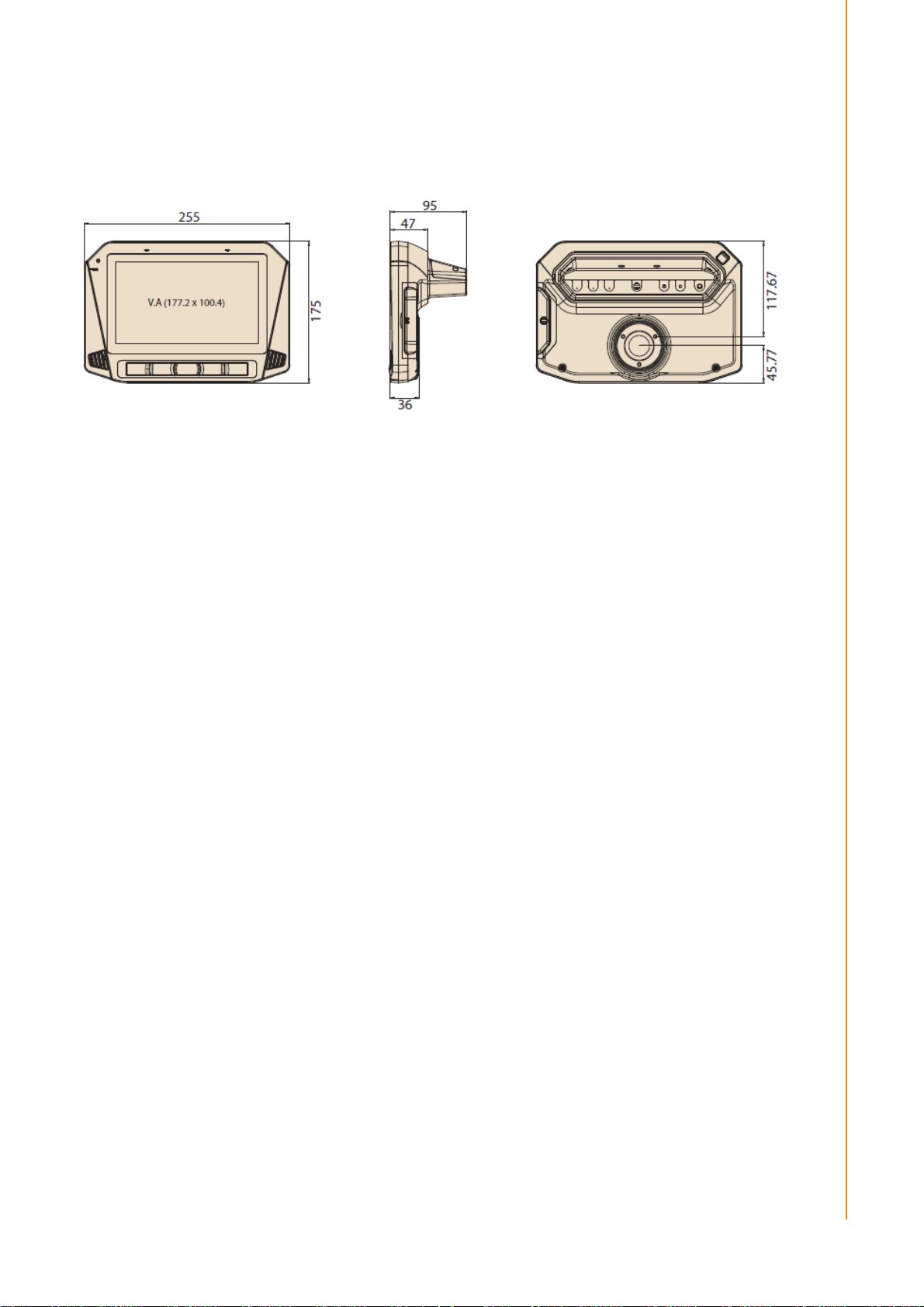
1.3 Dimensions
Figure 1.1 TREK-734 dimensions
Page 16

TREK-734 User Manual
6
Chapter 2
2 System Setup
This chapter details system setup
on TREK-734
Sections include:
A Quick Tour of the Computer
Box
Installation Procedures
Page 17

Page 18

TREK-734 User Manual
8
2.1 A Quick Tour of the TREK-734 Computer
Before starting to set up TREK-734, take a moment to become familiar with the
locations and functions of the connectors and ports, which are illustrated in the
figures below.
Figure 2.1 Front view of TREK-734
Figure 2.2 Rear view of TREK-734
Page 19

9
TREK-688 User Manual
Chapter 2
System Setup
1 2 3
2.2 Installation Procedures
2.2.1 Installing SIM car & Storage card
Remove enclosed I/O door screw and can install SIM Card & Micro SD card directly.
Figure 2.3 Installing SIM card & Storage card
2.2.2 Connecting Power
Connect the three pin waterproof power cord to the DC inlet of the Computing Box.
On the open-wire end, one pin is reserved for positive voltage and is marked, "+";
one pin is reserved for ground and is marked, "-"; and, one pin is reserved for the
ignition signal with an “ignition” mark.
Note! Ignition on/off setting: The TREK-734 supports an ignition on/off function
so that you can power on/off the TREK-734 via the ignition signal/volt-
age and connect the TREK-734 ignition switch.
Table 2.1: Pin Definition of Power Cord
Pin Definition Color
2.2.2 Power Connector
1 - Black
2 + Red
3 Ignition Orange
Figure 2.6 Power connector outlook
Page 20

TREK-734 User Manual
1
Table 2.2: Power connector
Signal
1
Ground
2
Power input
(9~32VDC)
3
Acc ignition input
Pin
Signal Pin
Page 21

Chapter 3
4 I/O Connectors
This chapter explains how to set
up the Computing Box hardware,
including instructions on setting.
Sections include:
I/O connectors pin assignment
Page 22

TREK-734 User Manual
28
Table 3.1: Power connector
Signal
1
Ground
2
Power input
(9~32VDC)
1 2 3
3.1 I/O Connectors Pin Assignment
3.3.1 Power connector
Pin
3 Acc ignition input
Signal Pin
3.3.1.1 Power in Jack Cable
Page 23

Table 1: Power
JACK
Cable
Pin
Depiction
PIN
Signal Depiction
Cable /Label
1
Power
Ground
■/-
2
Power Input (9 ~ 32 VDC)
■/+
3
Acc Ignition Input
■/IGN
■/Shield
19
GND_CODEC
20
MIC_IN1
21
LINE_IN_P
22
LINE_IN_N
23
LINE_OUT_R
24
LINE_OUT_L
25
ISO_DO_DRAIN1
26
ISO_DO_DRAIN2
27
ISO_DI_1
28
ISO_DI_2
29
ISO_DI_3
30
ISO_DI_4
31
ISO_DI_5
32
ISO_DI_6
33
ISO_GND
34
GND
35
CAN_H_R
36
CAN_L_R
Fuse Spec: 58V/10A*1
3.3.2 High Density Connector
Shield
Ground
1 GND
2 RS232_RTS1_HD
3 RS232_CTS1_HD
4 RS232_TX1_HD
5 RS232_RX1_HD
6 RS232_TX2_HD
7 RS232_RX2_HD
8 RS-232_DCD2_HD
9 CVBS_HD
10 GND
11 USB_HD_DP_H
12 USB_HD_DN_H
13 GND
14 +V5_HD_USB
15 GND
16 GND
17 +12V_HD_HD1
18 +12V_HD_HD1
Page 24

TREK-734 User Manual
30
36Pin connector cable pin define
3.3.2.1 High density cable
Pin number Pin name
1 GND_RS12
2 RS232_RTS1_HD
3 RS232_CTS1_HD
4 RS232_TX1_HD
5 RS232_RX1_HD
6 RS232_TX2_HD
7
RS232_RX2_HD
8 RS-232_DCD2_HD
9 CVBS_HD
10 GND_CVBS
11 USB_HD_DP_H
12 USB_HD_DN_H
13 GND_USB
14 +V5_HD_USB
15 GND_12V
16 GND_12V
17 +12V_HD_HD1
18 +12V_HD_HD1
19 GND_CODEC
20 MIC_IN1
21 LINE_IN_P
22 LINE_IN_N
23 LINE_OUT_R
24 LINE_OUT_L
25 ISO_DO_DRAIN1
26 ISO_DO_DRAIN2
27 ISO_DI_1
28 ISO_DI_2
29 ISO_DI_3
30 ISO_DI_4
31 ISO_DI_5
32 ISO_DI_6
33 ISO_GND
34 GND_CAN
35 CAN_H_R
Page 25

Pin
Signal Depiction
1
Vcc 2 USB_Data-
3
USB_Data+
4
GND
36 CAN_L_R
3.3.3 USB Connector
Connector type: Stack USB A-Type Receptacle DIP UB1112C-8FDE-4F
Table 3. : USB Connector
Page 26

TREK-734 User Manual
32
Chapter 4
6 Software Demo Utility
Setup
This chapter explains the software demo utility for TREK-734
Sections include:
„
Introduction
„
How to Set up Demo Utility
Page 27

4.1 Introduction
Advantech has developed demo utilities based on Advantech provided SDK APIs
to let user test the functions on TREK-734. This document describes the usage of
each demo utilities and also provide a basic concept of the application
development on TREK-734.
For technical support, contact Advantech application engineers worldwide. For
news updates, please visit our website : www.advantech.com
http://mrmforum.advantech.com/index.aspx
4.2 IVCP Demonstration
The IVCP demonstration application demonstrate the usage of MRM IVCP API which is a
lightweight interface between OS (Operating system) and IVCP (Intelligent Co-Processor)
allow user to access the status of machine and change machine behavior such as power
management, boot behavior, peripheral control etc.
4.2.1 Information
In this page, the demo application shows the current status and basic information.
and MRM forum :
Page 28

TREK-734 User Manual
34
4.2.2 Mode Control
In this page, you can toggle “AT Mode” and “Keep Alive Mode”.
Press “Save Default” to set current settings as default value of VPM controller.
Press “Load Default” to load the default values.
4.2.3 Low Voltage Protection
You can enable/disable and set the pre-boot/post-boot low voltage protection threshold in
this page.
Press “Get” to get the current threshold value and Press “Set” to set the value.
Press “Save Default” to set current value as default value of VPM controller.
Press “Load Default” to load the stored default values.
Page 29

4.2.4 Event Delay
4.2.4.1 Power control mechanism
TREK-734 provides VPM features to fulfill specific requirements. The basic mechanism is
shown in the following figure.
Page 30

TREK-734 User Manual
36
The power of system can be controlled with the following events:
Ignition ON
The ignition signal can be used to power on or shutdown the system. When the system is in an OFF
state and the ignition is turned ON, the VPM controller will countdown a delay period (ON_DELAY).
Once it counts to zero, the system will be powered on.
Ignition OFF
When the system is powered on and the ignition is turned off, the VPM controller will countdown a
delay period(OFF_EVENT_DELAY). During this period, if the ignition
is switched back to ON, the VPM controller will stop countdown and reset the OFF_EVENT_DELAY. If
OFF_EVENT_DELAY counts to zero, the VPM controller will trigger an power off event (i.e. power
button press). System and applications which receives this event can do pre-defined tasks, like storing
data and preparing to turn off the system.
After the event is triggered, VPM controller starts to countdown next delay period (HARD_OFF_DELAY).
If HARD_OFF_DELAY counts to zero, the system power will be cut off abruptly to avoid unexpected
Page 31

system hang. Aldo, once VPM controller enter the HARD_OFF_DELAY stage, the process cannot be
reversed.
Low power protection
To avoid draining power, low-power protection is to ensure that there is enough power
to start the machine. When the system is ON, the VPM controller will monitor the power voltage. If
the voltage is lower than the programmable threshold (LOW_THRESHOLD), the VPM controller will
start to countdown a delay(LOW_DELAY). During the stage of LOW_DELAY countdown, if voltage
goes back above LOW_THRESHOLD, the VPM controller will stop counting
down and exit.
If LOW_DELAY counts to zero, the VPM controller will trigger an power off event (i.e. power button
press) and starts to countdown next delay period (LOW_ HARD_DELAY). If LOW_ HARD_DELAY counts
to zero, the system power will be cut off abruptly to avoid draining the power.
4.2.4.2 Demonstration
You can set the delay and hard delay time of the low voltage event and ignition event.
Low Voltage Event
Delay:
The delay time before VPM trigger a power off event (i.e. power button press).
Hard Delay:
The delay time counted down after a power off event is triggered. VPM will force power off the
machine if the hard delay time is counted down to zero.
Ignition Event
On Delay:
The delay time before VPM trigger an power on event (power on the machine).
Off Delay:
The delay time before VPM trigger an power off event (i.e. power button press).
Hard Off Delay:
The delay time counted after an power off event is triggered. VPM will force power off the
machine if the hard delay time is counted down to zero.
Press “Save Default” to set current value as default value.
Press “Load Default” to load the stored default values.
Page 32

TREK-734 User Manual
38
4.2.5 Alarm
In this page, you can set the time and set alarm wakeup time to VPM controller and enable/disable the
alarm as a system wakeup source.
Press “Save Default” to set current value as default value.
Press “Load Default” to load the stored default values.
Page 33

4.2.6 Watchdog
In this page, you can enable/disable the watchdog function and set the count time (second) for the
watchdog to avoid unexpected system hang..
When watchdog is enabled, the VPM controller will start counting down the time set for watchdog and
power off the machine if it is counted to 0. You can press “Trigger” button while watchdog is counting
to reset the count down time and keep it counting.
Press “Save Default” to set current value as default value.
Press “Load Default” to load the stored default values.
Page 34

TREK-734 User Manual
40
4.2.7 G-Sensor
In this page, you can enable/disable the G-sensor. Also, you can set G-sensor as a system wakeup
source and set the threshold to trigger system wakeup.
Page 35

4.2.8 Peripheral
In this page, you can enable/disable the peripheral functions and set WWAN as system wakeup source.
Page 36

TREK-734 User Manual
42
4.2.9 Storage
In this page, you can save/load arbitrary data to the private storage (256 byte) on the machine.
Page 37

4.2.10 Digital I/O
In this page, you can monitor the digital input status and enable/disable digital output.
DI1 default is normal digital input and can be set as dedicated reverse signal input.
Page 38

TREK-734 User Manual
44
4.2.11 P-Sensor
In this page, you can monitor the p-sensor status and enable/disable it.
Page 39

4.3 VCIL Demonstration
The VCIL demonstration application demonstrate the usage of MRM VCIL (Communication
Interface Layer) API which allow user to access protocol easily.
4.3.1 Port selection
When first open VCIL demonstration app, you will see a port selection windows as following.
Please select the VCIL port path and press Connect button.
VCIL port path in different platforms have different nodes. The common path at Window is COM7.
Page 40

TREK-734 User Manual
46
Page 41

4.3.2 Information
In this page, the demo application shows the current status and basic information.
Page 42

TREK-734 User Manual
48
4.3.3 Option
In this page, you can the set the protocol for each port.
Page 43

4.3.4 CAN / J1939 / OBD2 / J1708 / J1587
To use CAN / J1939 / OBD2 / J1708 / J1587 protocol on each port, please click on corresponding tab to
switch to the page of specific protocol, then you can send/read message on specific port by setting the
detail items.
Page 44

TREK-734 User Manual
50
Page 45

4.4 Smart Display Demonstration
The smart display demonstration application demonstrate the usage of MRM SDP API which is a
lightweight interface between OS (Operating system) and SDP (Smart Display Co-Processor) allow user
to control the font-end display, backlight setting, hotkey, peripheral control, etc.
4.4.1 Information
In this page, the demo application shows the current status and basic information.
Page 46

TREK-734 User Manual
52
Page 47

4.4.2 Backlight
In this page, you can set the levels for backlight, the brightness for each level and the current
brightness level.
Page 48

TREK-734 User Manual
54
4.4.3 Hot key
In this page, you can monitor the press state of each hot key and set the LED brightness of the hot keys.
Page 49

4.4.4 Peripheral
In this page, you can control the status of peripheral devices.
Speaker
Enable/disable speaker volume.
Reserve gear
Enable/disable auto switch of display. If enabled, the display will be switched to camera view if
reverse gear detected and switched to LVDS view if reverse gear absent.
USB
Enable/disable power of front-end USB port.
Page 50

TREK-734 User Manual
56
4.5 GPS Demonstration
The GPS demonstration application demonstrate the usage of MRM GPS API which is a lightweight
interface between OS (Operating system) and GPS module allows user to easily get GPS information.
4.5.1 Port selection
When first open GPS demonstration app, you will see a port selection windows as following.
Please select the GPS port path and press Connect button. The common path at Window is COM3.
Page 51

4.5.2 Information
In this page, the demo application shows the current GPS status.
1. GPS Status
2. Function demonstration selection
3. Satellite location Information
4.5.3 NEMA
In this page, the demo application shows the incoming NMEA code. Check ' Save to file ' to logging the
NMEA code to file.
Page 52

TREK-734 User Manual
58
Page 53

Appendix A
A
This appendix explains the
optional peripherals installation
Page 54

TREK-734 User Manual
60
A-1 Installing Backup battery
A-2 Installing RAM mount kit
TREK-734 designed a RAM mount hole to support ram mount kit. Refer to
below dimension. It needs to use 3pcs M4x0.7x10L screws.
TREK-734 using as portrait monitor only.
Page 55

A-3 Installing IP cover
Page 56

www.advantech.com
Please verify specifications before quoting. This guide is intended for reference
purposes only.
All product specifications are subject to change without notice.
No part of this publication may be reproduced in any form or by any means,
electronic, photocopying, recording or otherwise, without prior written permission of the publisher.
All brand and produ ct names are trademarks or registered trademarks of their
respective companies.
© Advantech Co., Ltd. 2010
 Loading...