

Page 1

User Manual
TREK-305R
5.7” Display Solution for Vehicle
Application
Page 2

Copyright
This document is copyrighted, © 2008. All rights are reserved. The original manufacturer reserves the right to make improvements to the products described in this manual at any time without notice.
No part of this manual may be reproduced, copied, translated or transmitted in any
form or by any means without the prior written permission of the original manufacturer. Information provided in this manual is intended to be accurate and reliable.
However, the original manufacturer assumes no responsibility for its use, nor for any
infringements upon the rights of third parties that may result from such use.
Acknowledgements
Microsoft Windows® is a registered trademark of Microsoft Corp.
All other product names or trademarks are properties of their respective owners.
For more information on this and other Advantech products, please visit our websites
at:
http://www.advantech.com
http://www.advantech.com/eplatform
For technical support and service, please visit our support website at:
http://www.advantech.com/support
Part No. 2066A35010 Edition 1
Printed in China December 2008
TREK-305R User Manual ii
Page 3
Packing List
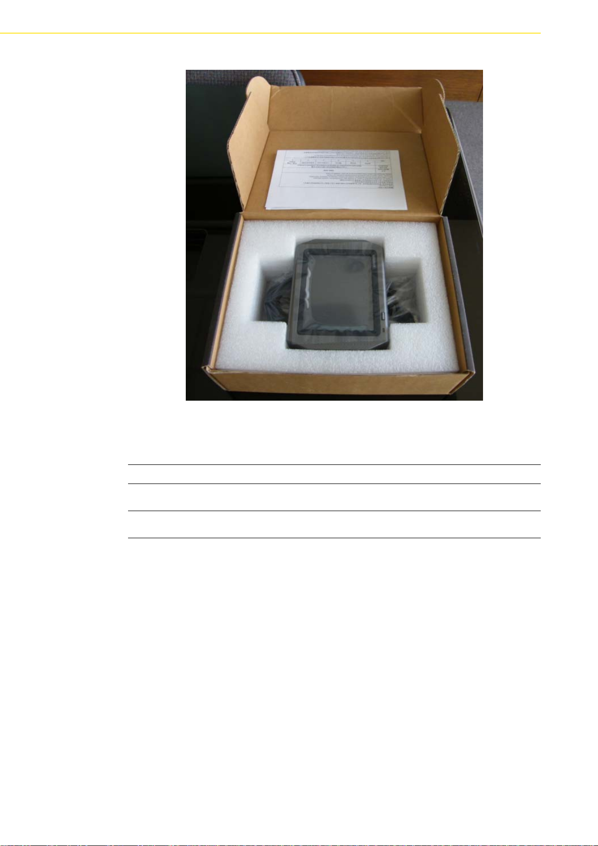
Before you begin installing your device, please make sure that the following materials
have been shipped:
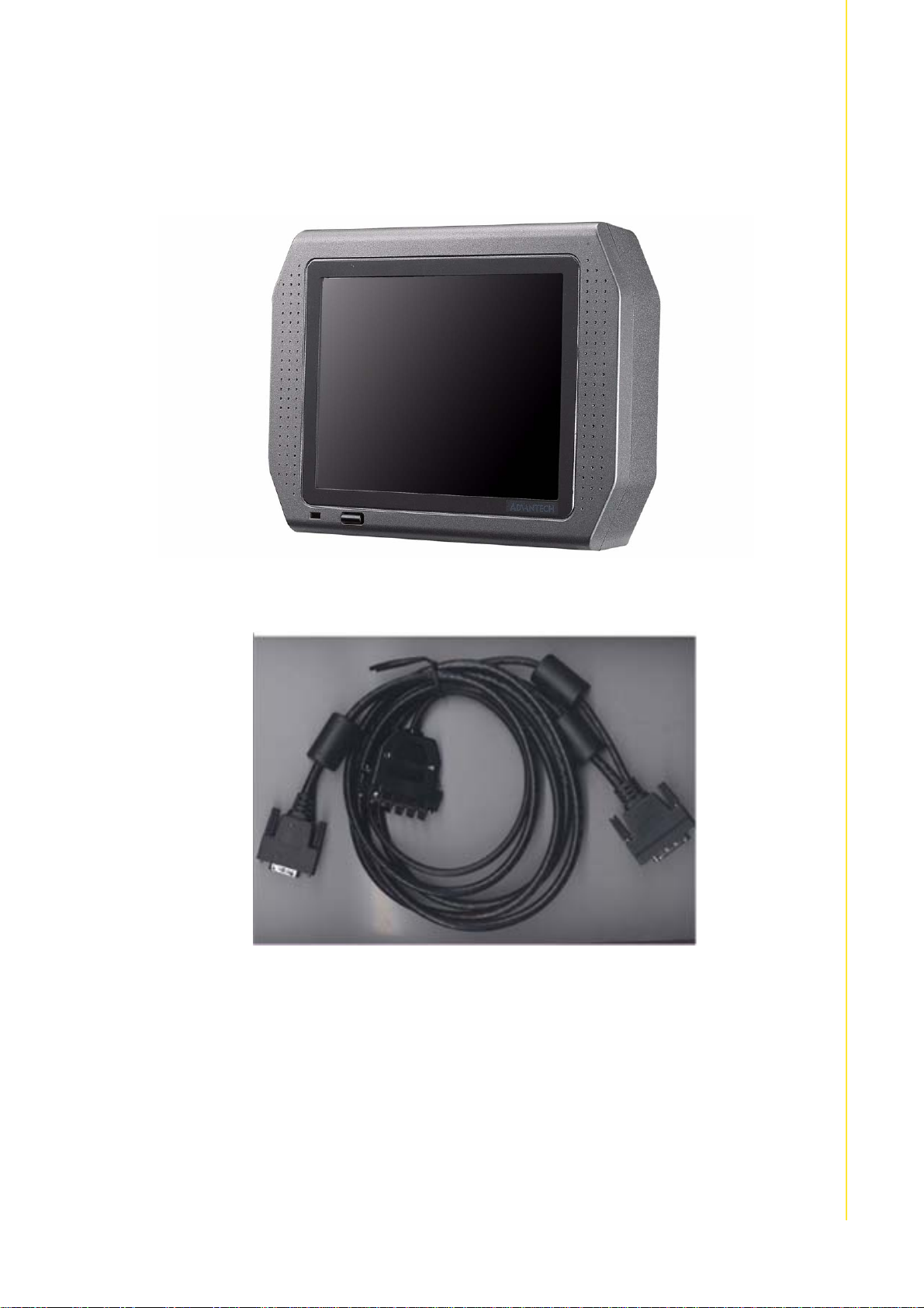
TREK-305 device
Display cable (Advantech P/N: 1700009873) to connect with VITA-350P
If any of these items are missing or damaged, contact your distributor or sales representative immediately.
iii TREK-305R User Manual
Page 4
Ordering information
Part Number Description
TREK-305R-FLA0E 5.7" color TFT LCD with touch screen, 2 Watt speaker, and Power
button
VITA-350P-GA0E MDT with GPS, GPRS, DI/O, RS232, LVDS (TREK is design com-
patible with VITA)
TREK-305R User Manual iv
Page 5
Declaration of Conformity
根據交通部低功率管理辦法規定:
第十二條
經型式認證合格之低功率射頻電機,非經許可,公司、商號或使用者均不得擅自變更
頻率、加大功率或變更原設計之特性及功能。
第十四條
低功率射頻電機之使用不得影響飛航安全及干擾合法通信;經發現有干擾現象時,應
立即停用,並改善至無干擾時方得繼續使用。前項合法通信,指依電信規定作業之無
線電信。低功率射頻電機須忍受合法通信或工業、科學及醫療用電波輻射性電機設備
之干擾。
FCC
This device complies with the requirements in part 15 of the FCC rules: Operation is
subject to the following two conditions:
1. This device may not cause harmful interference, and
2. This device must accept any interference received, including interference that
may cause undesired operation This equipment has been tested and found to
comply with the limits for a Class A digital device, pursuant to Part 15 of the
FCC Rules. These limits are designed to provide reasonable protection against
harmful interference when the equipment is operated in a commercial environment. This equipment generates, uses, and can radiate radio frequency energy
and, if not installed and used in accordance with the instruction manual, may
cause harmful interference to radio communications. Operation of this device in
a residential area is likely to cause harmful interference in which case the user
will be required to correct the interference at his/her own expense. The user is
advised that any equipment changes or modifications not expressly approved
by the party responsible for compliance would void the compliance to FCC regulations and therefore, the user's authority to operate the equipment.
Caution! There is a danger of a new battery exploding if it is incorrectly installed.
Do not attempt to recharge, force open, or heat the battery. Replace the
battery only with the same or equivalent type recommended by the manufacturer. Discard used batteries according to the manufacturer°Øs
instructions.
Additional Information and Assistance
1. Visit the Advantech web site at www.advantech.com where you can find the lat-
est information about the product.
2. Contact your distributor, sales representative, or Advantech's customer service
center for technical support if you need additional assistance. Please have the
following information ready before you call:
Product name and serial number
Description of your peripheral attachments
A complete description of the problem
The exact wording of any error message
v TREK-305R User Manual
Page 6

TREK-305R User Manual vi
Page 7

Contents
Chapter 1 General Information ............................1
1.1 Introduction ...............................................................................................2
Figure 1.1 VITA-350P and TREK-305R total solution .................2
1.2 Features.................................................................................................... 3
1.3 Quick Installation Guide ............................................................................4
Figure 1.2 - 2 m cable connecting VITA and TREK.....................4
Figure 1.3 Backside of TREK-305R............................................. 4
Figure 1.4 Front side of TREK-305R........................................... 5
Figure 1.5 26-pin connector......................................................... 5
Figure 1.6 36-pin connector......................................................... 5
Figure 1.7 Front side of VITA-350P.............................................7
1.4 System Dimensions ..................................................................................7
Figure 1.8 System Dimensions.................................................... 7
Appendix A LCD Specification................................9
A.1 LCD General Specification......................................................................10
A.2 LCD Optical Specification .......................................................................11
Appendix B Touch Panel Specification................13
B.1 Enviroment Specification......................................................................... 14
B.2 Mechanical Characteristics .....................................................................14
B.3 Mechanical Characteristics .....................................................................14
vii TREK-305R User Manual
Page 8

TREK-305R User Manual viii
Page 9

Chapter 1
1 General Information
This chapter gives background
information on the TREK-305.
Sections include:
Introduction
Features
Quick Installation Guide
System Dimensions
Page 10
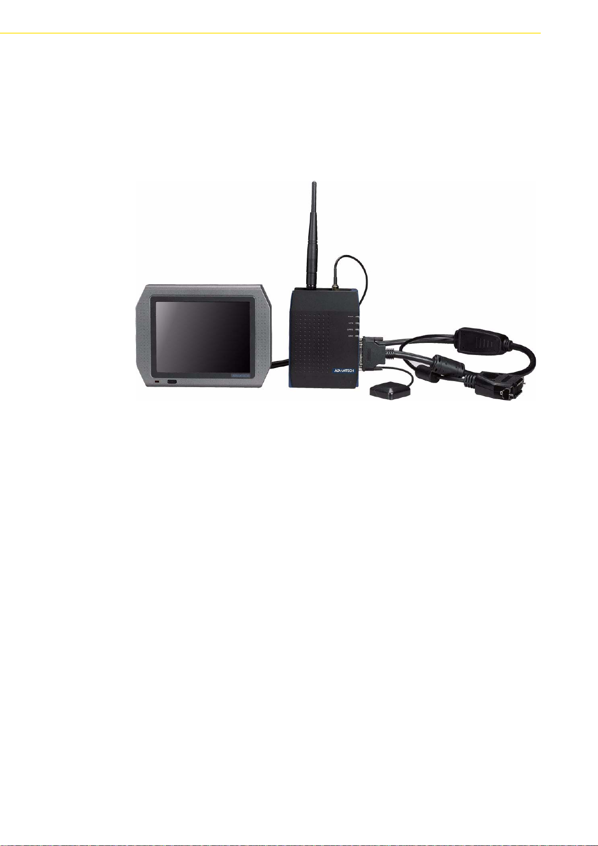
1.1 Introduction
Advantech TREK-305R uses a Toshiba 5.7” LCD panel with touch (Toshiba model
no: LTA057A344F-12), which is the perfect size to fit into tight spaces for fleet management and dispatching purposes. TREK-305R of 5.7" touch screen panel provides
excellent capabilities and features with industrial standard VESA mounting holes,
light-weight housing, and convenient mounting accessories. The TREK-305 design is
compatible with VITA-350P-GA0E.
Figure 1.1 VITA-350P and TREK-305R total solution
TREK-305R User Manual 2
Page 11

1.2 Features
Display
I/O
Power
Mechanical
Enviroment
Certification
Chapter 1 General Information
Type QVGA TFT LCD (Toshiba LT057A344F)
Colors 18 bits (256 k)
Resolution 320 x 240
Size (disgonal) 5.7” (4:3)
Pixel Pitch 0.36 (W) x 0.36 (W)
View Angle (H°, V°) H: 140°, V: 120°
Brightness 320 nits by LED backlight
Touchscreen 4-wire resistive
Contrast Ratio 500
Backlight Life Time (hrs) 20000
LVDS 1 x 26 pin connector
Audio 2 Watt speaker out
DC Input 3.3 V and 5 V
LCD power button Push button
Power Consumption 1.3 W
Mounting VESA mount (30 x 38 mm, 75 x 75 mm)
Material PC
Weight 400 (g)
Dimension W x H x D (mm) 168.55 x 128.05 x 35.6
Operating Temperature -10 ~ 70°C
Storage Temperature -30 ~ 80°C
Vibration MIL-STD-810F 514.5C-3
FCC FCC 47 CFR part 15B
IC ICES-003 issue 4
CE EN55022/55024
E13 ECE-R10 (v.03)
BSMI CNS 13438
3 TREK-305R User Manual
Page 12
1.3 Quick Installation Guide
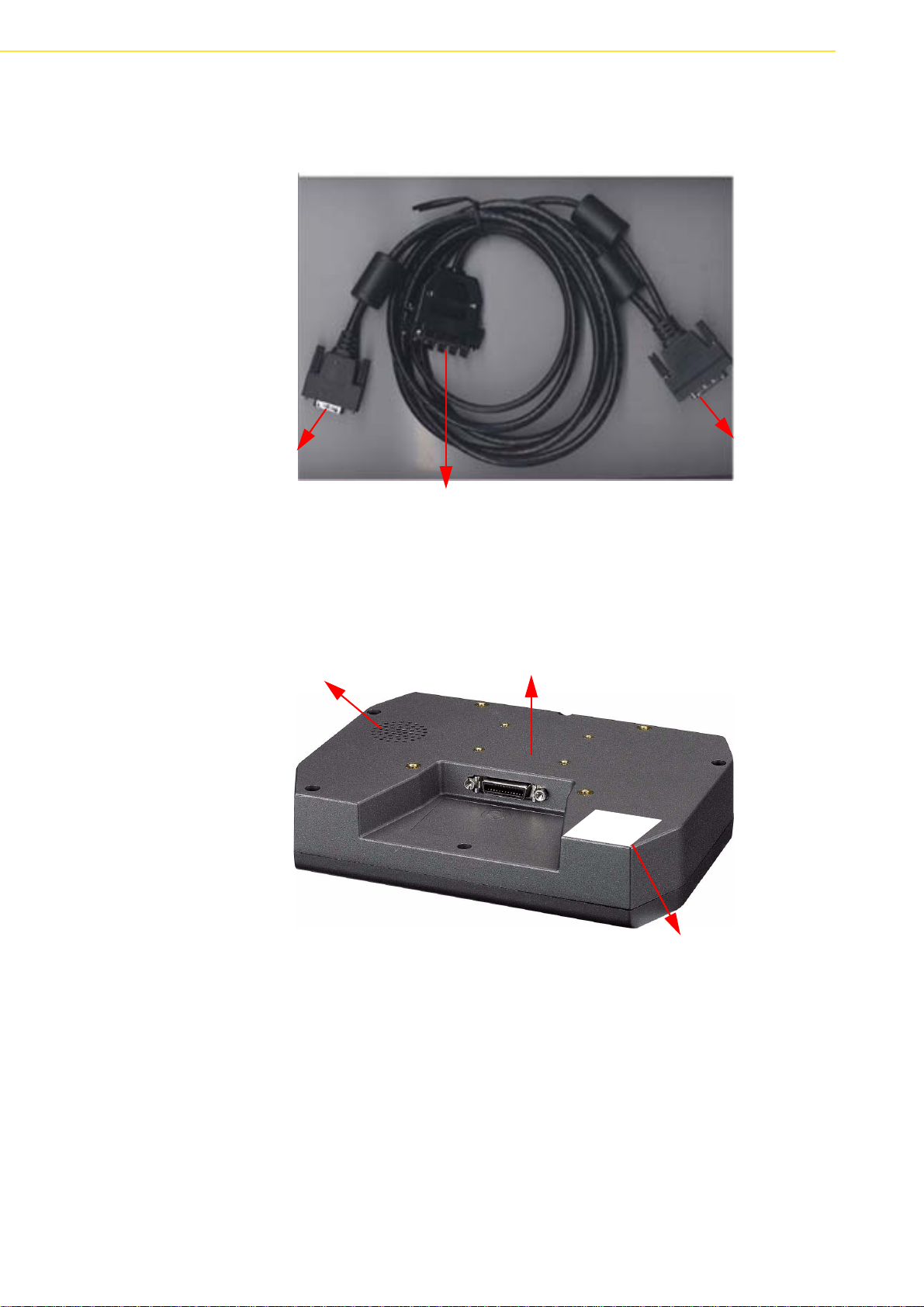
1. Connect 26pin connector to 5.7” panel.
26 pin (S1)
connect to
TREK-305R
Figure 1.2 - 2 m cable connecting VITA and TREK
2. Connect 36pin connector to VITA-350P.
DI/O (default: 4 Digital output)
2 types of VESA mount:
Speaker
30 x 38mm and 75 x 75mm
36pin (S2)
connect to
VITA series
W
a
r
r
a
n
t
y
v
o
i
d
i
f
r
e
m
o
v
e
d
Please refer to Advantech RMA policy
http://erma.advantech.com.tw/GlobalPolicy.asp
Figure 1.3 Backside of TREK-305R
TREK-305R User Manual 4
Warranty void if sticker is removed.
Page 13
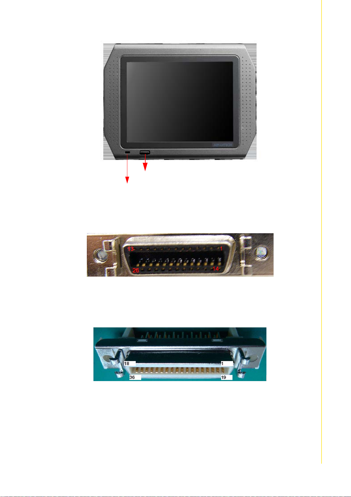
Power button to control LCD backlight On/Off
When LCD backlight is on, red LED light is on
Figure 1.4 Front side of TREK-305R
Chapter 1 General Information
Pin definition (on TREK)
Connector vendor: 3M Touch systems, p/n: 10226-55G3PC
Figure 1.5 26-pin connector
Pin definition (on VITA)
Connector vendor: 3M Touch systems, p/n: 10236-55G3PC
Figure 1.6 36-pin connector
5 TREK-305R User Manual
Page 14

36 pin CITA-350P Side 26 pin TREK-305R Side
1 LVDS Data0+ 1 LVDS Data0+
2 LVDS Data0- 2 LVDS Data03 LVDS Data1+ 3 LVDS Data1+
4 LVDS Data1- 4 LVDS Data15 GND 5 GND
6 T/S signal X+ 6 T/S signal X+
7 T/S signal Y+ 7 T/S signal Y+
8 T/S signal X- 8 T/S signal X9 T/S signal Y- 9 T/S signal Y10 GND 10 GND
11 GPIO 11 GPIO
12 DC +5 V 12 DC +5 V
13 DC +5 V 13 DC +5 V
14 LVDS Data2+ 14 LVDS Data2+
15 LVDS Data2- 15 LVDS Data216 LVDS Data3+ 16 LVDS Data3+
17 LVDS Data3- 17 LVDS Data318 LVDS Clock+ 18 LVDS Clock+
19 LVDS Clock- 19 LVDS Clock20 GND 20 GND
21 Line in 21 Line in
22 GPIO 22 GPIO
23 GPIO 23 GPIO
24 GPIO 24 GPIO
25 DC +3.3 V 25 DC +3.3 V
26 DC +3.3 V 26 DC +3.3 V
5 pin DI/DO Side
27 GPIO1 1 GPIO1
28 GPIO2 2 GPIO2
29 GPIO3 3 GPIO3
30 GPIO4 4 GPIO4
31 GND 5 GND
32 X (empty PIN)
33 X (empty PIN)
34 X (empty PIN)
35 X (empty PIN)
36 X (empty PIN)
TREK-305R User Manual 6
Page 15

TREK-305R is design compatible with VITA-350P.
Figure 1.7 Front side of VITA-350P
Chapter 1 General Information
1.4 System Dimensions
Unit: mm
Power button height: 1.41 mm
Figure 1.8 System Dimensions
7 TREK-305R User Manual
Page 16

TREK-305R User Manual 8
Page 17

Appendix A
A LCD Specification
Page 18

A.1 LCD General Specification
Item Specifications
Display Mode
1)
VIewing Direction 6 o’clock (in direction of maximum contrast)
Driving Method TFT active matrix
Input Signals
Dimensional Outline
Active Area 115.2 (W) x 86.4 (H) (mm)
Viewing Area 115.4 (W) x 86.6 (H) (mm)
Number of Pixels
Pixel Pitch
3)
3
Pixel Arrangement
Surface treatment Anti-glare and hard cost 3H on LCD surface
Backlight 18 LEDs (3 rows) for sidelighting
TN colors (64 gray scales, 256 k colors)
CLK (clock), DE (Data Enable signal)
H-sync, V-sync (Synchronization signal)
R5, R4, R3, R2, R1, R0 (Red display data)
G5, G4, G3, G2, G1, G0 (Green display data)
B5, B4, B3, B2, B1, B0 (Blue display data)
R/L, U/D (Reverse Scan Control)
2)
144.0 (W) x 104.6 (H) x 10.0 max. (D) (mm)
320 (W) x 240 (H) (mm)
0.36 (W) x 0.36 (H) (mm)
3
RGB vertical stripes
Note! 1. k=1024.
2. Excluding backlight cables.
3. Display area address is as follows.
TREK-305R User Manual 10
Page 19

A.2 LCD Optical Specification
Appendix A LCD Specification
Item Symbol Conditions
=180
Viewing Angle CR >=10
Contrast Ratio CR
t
Response Time
Luminance L
Luminance Uniformity LUNF 60 70 - %
Red
Green
Chromaticity
Blue
White
ON
t
OFF
X
Y
X
Y
X
Y
X
Y
R
R
G
G
B
B
W
W
=0°, =0°
=0°, =0°
=0°, =0°
Gray Scale Level=163
(White)
Gray Scale Level: L63
=0°, =0°
Ditto
Ditto
Ditto
=0
=90
=190
Specifications
Min. Typ. Max.
30 50 - °
°
40 70 - °
°
40 70 - °
°
40 70 - °
°
350 500 - -
-1525ms
-2535ms
255 320 -
0.52 0.59 0.66 -
0.27 0.34 0.41 -
0.29 0.36 0.43 -
0.48 0.55 0.62 -
0.08 0.15 0.22 -
0.05 0.12 0.19 -
0.25 0.32 0.39 -
0.27 0.34 0.41 -
Unit Remark
cd/m
2
/F=12 mA
Note! 1. Refer to “11. Measuring Method“.
2. The above test limit must be applied for initial use. Characteristics
will be shifted by long period operation, but it is not irregular phenomena. Theoretically brightness characteristics will be decreased
due to color shift.
11 TREK-305R User Manual
Page 20

TREK-305R User Manual 12
Page 21

Appendix B
B Touch Panel
Specification
Page 22

B.1 Enviroment Specification
Chemical Resistance
(top surface)
Condition: Tested after leaving the chemical on the surface for 3 minutes being wiped
off by cloth.
Judgment: Must be no effect in appearance.
Toluene, Acetone, Methanol, Alcohol, Ethylacetate, Artificial sweat,
Petroleum ether
B.2 Mechanical Characteristics
Operating Life Input (finger) 10,000,000 hits (Note 1)
Character Input (pen) 100,000 characters (Note 2)
Note! 1. Testing rod (Figure 1), Load 250 g, Cycle 2hit/sec;
2. Testing rod (Figure 2), load 250 g, Input size 10 x 10 mm, Input
character A to Z / minute.
These (finger and pen) are tested at same point of the panel surface,
and all point will become dis-functin after test.
Silicon Rubber
(Hardness: 60°)
Tip: R = 4.0
Figure 1 Testing rod 1 Figure 2 Testing rod 2
Polyacetal resin
Tip: R = 0.8
B.3 Mechanical Characteristics
Pressing Force Max 100N (Note 3)
Activation Force 0.05N to 1.0N
Surface Hardness Over 3H (by JIS pencil hardness) (Note 4)
Note! 3. Testing with rubber rod. (Ø 16 mm, Hardness 60°), Time: 5 s, Center
of LCD surface. If you apply pressure over 100N, white spots and
dark spots will be occured.
4. T esting pressure is 750 g. If you use 3H hardness pencil with under
750 g pressure, the surface will not be damaged. But using a 4H
hard pencil, the surface may be damaged. Please use a 3H pencil
or under with under 750 g pressure.
TREK-305R User Manual 14
Page 23

Appendix B Touch Panel Specification
15 TREK-305R User Manual
Page 24

www.advantech.com
Please verify specifications before quoting. This guide is intended for reference
purposes only.
All product specifications are subject to change without notice.
No part of this publication may be reproduced in any form or by any means,
electronic, photocopying, recording or otherwise, without prior written permission of the publisher.
All brand and product names are trademarks or registered trademarks of their
respective companies.
© Advantech Co., Ltd. 2008
 Loading...