

Page 1

PCA-6359 Series
Full-size Pentium® MMX 266
PCI/ISA-bus CPU card
User’s Manual
Page 2

Copyright notice
This document is copyrighted, 2000, by Advantech Co., Ltd. All
rights are reserved. The original manufacturer reserves the right to
make improvements to the products described in this manual at any
time without notice.
No part of this manual may be reproduced, copied, translated or
transmitted in any form or by any means without the prior written
permission of the original manufacturer. Information provided in this
manual is intended to be accurate and reliable. However, the original
manufacturer assumes no responsibility for its use, nor for any
infringements upon the rights of third parties which may result from
its use.
Acknowledgements
Award is a trademark of Award Software International, Inc.
IBM, PC/AT, PS/2 and VGA are trademarks of International Business
Machines Corporation.
Intel and Pentium are trademarks of Intel Corporation.
Microsoft Windows® is a registered trademark of Microsoft Corp.
UMC is a trademark of United Microelectronics Corporation.
All other product names or trademarks are properties of their
respective owners.
For more information on this and other Advantech products, please
visit our websites at: http://www.advantech.com
http://www.advantech.com/nc
For technical support and service, please visit our support website at:
http://support.advantech.com
This manual is for the PCA-6359 Series Rev. A1.
Part No. 2006635901 2nd Edition
Printed in T aiwan December 2000
Page 3

Packing List
Before installing your card, make sure that the following materials
have been received:
• 1 PCA-6359 Series single board computer
• 1 CD-ROM driver utility
• 4 SCSI driver disks (optional)
• 2 hard disk drive (IDE) interface cables (40-pin)
• 1 floppy disk drive interface cable (34-pin)
• 1 printer cable and 1 serial port cable kit
• 1 PS/2 keyboard and PS/2 mouse adapter
• 1 Ultra Wide SCSI cable (optional)
• 1 ATX-to-PS/2 power cable
• 1 warranty certificate
If any of these items are missing or damaged, contact your distributor
or sales representative immediately.
Optional Devices
• 1 USB cable (part no. 1700100170)
• 1 6-pin mini-DIN keyboard and PS/2 mouse adapter
(part no. 1700060201)
Page 4

PCA-6359 Series Comparison Table
82559ER
266 MHz (MMX)
fi
266 MHz (MMX) Intel
fi
266 MHz (MMX) Intel
fi
fi
10/100Base-T,
Intel
Ultra Wide SCSI
Symbios SYM53C875E
82559ER
fi
10/100Base-T,
Intel
fi
Model PCA-6359L PCA-6359V PCA-6359VE PCA-6359F
x C&T 69000 C&T 69000 C&T 69000
xx
xxx
2222
430TX 430TX 430TX 430TX
266 MHz (MMX) Intel
512 KB 512 KB 512 KB 512 K B
Award, P&P Award, P&P Award, P&P Award, P&P
256 MB SDRAM 256 MB SDRAM 256 MB SDRAM 256 MB SDRAM
Intel
CPU
System
Chipset
BIOS
L2 Cache
VGA
CRT/LCD
LAN
Max. System
RAM
SCSI
4444
USB
2S/1P !!!!
EIDE
Also refer to the PCA-6359 Series features elsewhere in this manual
Page 5

Contents
Chapter 1 Hardware Configuration ...................................... 1
1.1 Introduction .................................................................................2
Embedded Pentium® MMX CPU .................................................2
Guaranteed long product supply time ..........................................2
1.2 Features ........................................................................................3
1.3 Specifications ...............................................................................5
Standard SBC functions................................................................ 5
VGA function (PCA-6359V/VE/F only)......................................5
Ethernet controller functions (PCA-6359VE/F only) .................. 6
SCSI function (PCA-6359F only) ................................................6
Mechanical and environmental specifications ............................. 6
1.4 Board Layout: Main Features ................................................... 7
1.5 Safety Precautions.......................................................................8
1.6 Jumper Settings........................................................................... 9
1.6.1 Clear CMOS (J1) ............................................................... 10
1.6.2 Watchdog output (J2) ........................................................ 10
1.6.3 44-pin LCD power select (J4) ........................................... 11
1.6.4 DiskOnChip® 2000 Flash disk address select (J3) ............12
1.7 System Memory......................................................................... 14
1.7.1 Sample calculation: DIMM memory capacity ..................14
1.7.2 Supplementary information about DIMMs .......................15
1.8 Memory Installation Procedures............................................. 15
Chapter 2 Connecting Peripherals..................................... 17
2.1 Board Layout: Connector Locations ...................................... 18
2.2 Primary (CN1) and Secondary (CN2) IDE Connectors........21
2.3 Floppy Drive Connector (CN3) ............................................... 22
2.4 Parallel Port Connector (CN4) ................................................22
2.5 Ultra Wide SCSI Connector (CN5) ......................................... 23
2.6 USB Connector (CN6) .............................................................. 23
2.7 VGA Connector (CN7) .............................................................2 4
2.8 Ethernet Connector (CN8) .......................................................24
2.9 Serial Ports (CN9: COM1; CN10: COM2) ............................ 25
2.10 PS/2 Keyboard and Mouse Connector (CN11) ......................26
Page 6

2.11 External Keyboard Connector (CN12)................................... 26
2.12 IR Connector (CN13)................................................................2 6
2.13 Front Panel Connectors
(CN16, CN17, CN18, CN19 and CN21) ..................................2 7
2.13.1 Keyboard lock and power on LED (CN16) .................... 2 7
2.13.2 External speaker (CN17) .................................................27
2.13.3 Reset (CN18) ...................................................................27
2.13.4 IDE LED (CN19)............................................................. 27
2.13.5 ATX soft power switch (CN21) ...................................... 28
2.14 ATX Power Control Connectors (CN20 and CN21) .............28
2.14.1 ATX feature connector (CN20) and soft power switch
connector (CN21) ............................................................ 28
2.14.2 Controlling the soft power switch ................................... 2 9
2.15 LCD Inverter Connector (CN23) ............................................ 29
2.16 24-bit LCD Display Connector (CN24)...................................30
2.17 36-bit LCD Display Connector (CN25)...................................30
2.18 Ultra SCSI Connector (CN27) .................................................31
Chapter 3 Award BIOS Setup ............................................. 33
3.1 Introduction ...............................................................................34
3.2 Entering Setup ...........................................................................34
3.3 Standard CMOS Setup .............................................................35
3.3.1 CMOS RAM backup .........................................................35
3.4 BIOS Features Setup ................................................................36
3.4.1 Virus Warning....................................................................36
3.4.2 CPU Internal Cache/External Cache ................................. 37
3.4.3 Boot Sequence ................................................................... 37
3.4.4 Boot Up Floppy Seek.........................................................37
3.4.5 Boot Up NumLock Status..................................................38
3.4.6 Typematic Rate Setting......................................................38
3.4.7 Typematic Rate (Char/Sec)................................................38
3.4.8 Typematic Delay (msec).................................................... 38
3.4.9 Security Option ..................................................................38
3.4.10 OS Select for DRAM>64 MB ......................................... 39
3.4.11 PCI/VGA Palette Snoop .................................................. 39
3.4.12 Video BIOS Shadow........................................................39
3.4.13 C8000 - CFFFF Shadow/DC000-DFFFF Shadow .......... 39
Page 7

3.5 Chipset Features Setup............................................................. 40
3.5.1 SDRAM (CAS Lat / RAS-to-CAS) ...................................40
3.5.2 DRAM Speculative Read...................................................41
3.5.3 16 Bit I/O Recovery Time / 8 Bit I/O Recovery Time......41
3.5.4 Memory Hole At 15M-16M .............................................. 4 1
3.6 Power Management Setup .......................................................42
3.6.1 Power Management ........................................................... 42
3.6.2 PM Control by APM.......................................................... 42
3.6.3 Video Off Method..............................................................43
3.6.4 MODEM Use IRQ .............................................................43
3.6.5 HDD Power Down ............................................................. 43
3.6.6 ZZ Active in Suspend ........................................................43
3.6.7 PCI/VGA Act-Monitor ...................................................... 43
3.6.8 Soft-Off by PWR-BTTN ...................................................44
3.6.9 PowerOn by Ring...............................................................44
3.6.10 PowerOn by Alarm ..........................................................44
3.7 PnP PCI Configuration Setup..................................................45
3.7.1 IRQ-xx assigned to : PCI/ISA PnP.................................... 45
3.7.2 DMA-x assigned to : PCI/ISA PnP ................................... 46
3.8 Load BIOS Defaults ..................................................................46
3.9 Load Setup Defaults.................................................................. 46
3.10 Integrated Peripherals.............................................................. 47
3.10.1 IDE HDD Block Mode ....................................................47
3.10.2 IDE Primary Master/Slave PIO/UDMA Mode,
IDE Secondary Master/Slave PIO/UDMA Mode (Auto) 47
3.10.3 On-Chip PCI IDE Primary/Secondary ............................ 48
3.10.4 Onboard FDC Controller .................................................48
3.10.5 Onboard Serial Port 1 (3F8H/IRQ4) ............................... 4 8
3.10.6 Onboard Serial Port 2 (2F8H/IRQ3) ............................... 4 8
3.10.7 UART Mode Select .........................................................48
3.10.8 UART2 Duplex Mode ..................................................... 48
3.10.9 RxD, TxD Active .............................................................48
3.10.10 Onboard Parallel Port (378H/IRQ7)..............................49
3.10.11 Parallel Port Mode (ECP + EPP) ................................... 49
3.10.12 ECP Mode Use DMA .................................................... 4 9
3.11 Password Setting ....................................................................... 49
3.12 IDE HDD Auto Detection .........................................................50
3.13 Save & Exit Setup .....................................................................50
3.14 Exit Without Saving.................................................................. 50
Page 8

Chapter 4 PCI SVGA Setup (PCA-6359V/VE/F only)......... 51
4.1 Introduction ...............................................................................52
4.1.1 Chipset ...............................................................................52
4.1.2 Display memory................................................................. 5 2
4.1.3 Display types......................................................................52
4.2 Installation of SVGA Driver ....................................................53
4.2.1 Installation for Windows 95 ..............................................53
4.2.2 Installation for Windows 98 ..............................................54
4.2.3 Installation for Windows NT .............................................57
Chapter 5 PCI Bus Ethernet Interface
(PCA-6359VE/F only).......................................... 63
5.1 Introduction ...............................................................................64
5.2 Installation of Ethernet Driver ................................................64
5.2.1 Installation for MS-DOS and Windows 3.1 ......................64
5.2.2 Installation for Windows 95 ..............................................65
5.2.3 Installation for Windows 98 ..............................................66
5.2.4 Installation for Windows NT .............................................72
5.3 Further Information .................................................................76
Chapter 6 SCSI Setup and Configurations
(PCA-6359F only)................................................ 77
6.1 Introduction ...............................................................................78
6.2 Before You Begin ......................................................................78
6.3 Basic Rules for SCSI Host Adapter and Device Installation 79
6.4 Configuring the SCSI Adapter ................................................79
6.5 SCSI Terminators ..................................................................... 80
6.6 SDMS Drivers............................................................................ 81
Page 9

Appendix A Programming the Watchdog Timer .............. 83
A.1 Programming the Watchdog Timer........................................ 84
Appendix B Pin Assignments............................................. 87
B.1 IDE Hard Drive Connector (CN1, CN2) ................................88
B.2 Floppy Drive Connector (CN3) ...............................................8 9
B.3 Parallel Port Connector (CN4) ................................................90
B.4 Ultra Wide SCSI Connector (CN5) .........................................91
B.5 USB Connector (CN6) ..............................................................92
B.6 VGA Connector (CN7) .............................................................92
B.7 Ethernet 10/100Base-T RJ-45 Connector (CN8) ................... 93
B.8 COM1/COM2 RS-232 Serial Port (CN9, CN10) ...................93
B.9 Keyboard and Mouse Connector (CN11) ...............................94
B.10 External Keyboard Connector (CN12)................................... 94
B.11 IR Connector (CN13)................................................................9 5
B.12 CPU Fan Power Connector (CN14) ........................................95
B.13 Power LED and Keylock Connector (CN16) .........................9 6
B.14 External Speaker Connector (CN17) ......................................96
B.15 Reset Connector (CN18)...........................................................9 7
B.16 HDD LED Connector (CN19) ..................................................97
B.17 ATX Feature Connector (CN20) .............................................97
B.18 LCD Connector (CN23)............................................................98
B.19 24-bit LCD Display Connector (CN24)...................................99
B.20 36-bit LCD Display Connector (CN25).................................100
B.21 System I/O Ports......................................................................101
B.22 DMA Channel Assignments ...................................................102
B.23 Interrupt Assignments ............................................................102
B.24 1st MB Memory Map..............................................................103
B.25 PCI Bus Map............................................................................103
Appendix C DiskOnChip® 2000 Installation Guide ......... 105
C.1 DiskOnChip® 2000 Quick Installation Guide.......................106
C.1.1 DiskOnChip® 2000 installation instructions ................... 106
C.1.2 Addtional information and assistance.............................107
Appendix D LCD Services................................................. 109
D.1 LCD Services ........................................................................... 110
Page 10

1
CHAPTER
Hardware
Configuration
This chapter gives background
information on the PCA-6359 Series. It
then shows you how to configure the card
to match your application and prepare it
for installation into your PC.
Sections include:
• Introduction
• Specifications
• Board layout
• Safety precautions
• Jumper settings
• System memory
• Memory installation procedures
Page 11

1.1 Introduction
The PCA-6359 Series is a full-size CPU card designed with an
on-board Intel® Pentium® MMX CPU. Featuring powerful onboard
functions such as VGA, LCD, LAN, SCSI and SSD, the versatile
PCA-6359 Series can meet the needs of a great many different
applications.
Embedded Pentium® MMX CPU
The PCA-6359 Series is equipped with Intel's new embedded Pentium® Tillamook MMX 266 MHz CPU. The CPU provides high
performance with low power consumption and better thermal management.
Guaranteed long product supply time
In addition to the CPU, all the major components of the PCA-6359
Series are Intel® EMD solutions. These include the 430 TX system
chipset, C&T 69000 VGA/LCD controller, and 82559ER
10/100Base-T Ethernet. Unlike regular commercial solutions, Intel
EMD solutions provide higher system stability and longer product
supply time (Intel EMD products' typical life cycle is 5 years). This
guarantee is particularly important for end systems that will last for
years.
2
PCA-6359 Series User's Manual
Page 12

1.2 Features
1. ATX soft power switch: Through the BIOS, the power button can
be defined as the "Standby" (aka "Suspend" or "Sleep") button or
as the "Soft-Off" button (see Section 3.6.8 Soft-off by PWRBTN). Regardless of the setting, pushing the power button for
more than 4 seconds will enter the Soft-Off mode.
2. Wake-on-modem (requires modem): This allows a computer to be
turned on remotely through an internal or external modem. Users
can thus access information on their computers from anywhere in
the world!
3. Message LED: Chassis LEDs now act as information providers.
The way a particular LED illuminates indicates the stage the
computer is in. A single glimpse provides useful information to the
user.
4. Jumper free mode: When enabled, this allows processor settings
and easy overclocking of frequency and Vcore voltages all
through the BIOS setup. Easy-to-use DIP switches instead of
jumpers are included in case you want to manually adjust the
processor's external frequency.
Chapter 1 Hardware Configuration
3
Page 13

5. CMOS RAM backup: When BIOS CMOS setup has been
completed, data in the CMOS RAM is automatically backed up to
the Flash ROM. This is particularly useful in industrial environments which may cause soft errors. Upon such an error occurring,
BIOS will check the data, and automatically restore the original
data for booting.
6. More!:
• Additional metal bracket for CPU stabilization
• Power On by Alarm: Powers up your computer at a certain
time
• Standard IR supports optional remote control package for
wireless interfacing with external peripherals, personal
gadgets, or an optional remote controller
• Virus warning: During and after system boot-up, any attempt
to write to the boot sector or partition table of the hard disk
drive will halt the system. In this case, a warning message will
be displayed. You can then run your anti-virus program to
locate the problem
4
PCA-6359 Series User's Manual
Page 14

1.3 Specifications
Standard SBC functions
• CPU: Intel® Pentium® MMX CPU 266 MHz
• BIOS: Award 2 Mbit Flash BIOS, supports Plug & Play, APM 1.2,
Ethernet boot ROM, and HDD/SCSI/ZIP/CD/Floppy/LS120 boot
selection
• Chipset: Intel® 430TX
• L2 cache: 512 KB PB SRAM
• System memory: Two 168-pin DIMM sockets support SDRAM
memory module from 16 MB to 256 MB
• PCI IDE interface: Two Enhanced IDE interfaces. Support 4 IDE
devices, PIO mode 4 with bus mastering up to 16.7 MB/sec, Ultra
DMA mode up to 33 MB/sec
• Floppy disk drive interface: Supports up to two floppy disk drives:
3½" (720 KB or 1.44 MB) and/or 5¼" (360 KB or 1.2 MB)
• Parallel port: One parallel port , supports EPP/ECP
• Serial ports: Two RS-232
• Two USB ports
• Watchdog timer: Can generate a system reset or IRQ 11. Software
enabled/disabled. Time interval is from 1 ~ 63 seconds. Jumperless
with run-time setup
• SSD (optional): Supports DOC® 2000 up to 144 MB
VGA function (PCA-6359V/VE/F only)
• Controller: C&T 69000 (69030 upon request), supports CRT and
36-bit LCD display types
• Display memory: 2/4 MB SDRAM built-in (upon request)
• Display resolution: Up to 1280 x 1024 @ 256 colors (16 million
colors @ 4 MB)
Chapter 1 Hardware Configuration
5
Page 15

Ethernet controller functions (PCA-6359VE/F only)
• Controller: Intel® 82559ER, 10/100 Mbps
• I/O address switchless setting
• Connector type: RJ-45
• Boot ROM: Built-in system (optional)
SCSI function (PCA-6359F only)
• Controller: Symbios SYM53C875E
• PCI SCSI: Supports Ultra Wide SCSI 8-bit or 16-bit interface, up to
40 MB/s
Mechanical and environmental specifications
• Max. power requirement: + 5 V @ 2.52 A
• Operating temperature: 0 ~ 60° C (32 ~ 140° F)
• Size: 338 x 122 mm
6
PCA-6359 Series User's Manual
Page 16
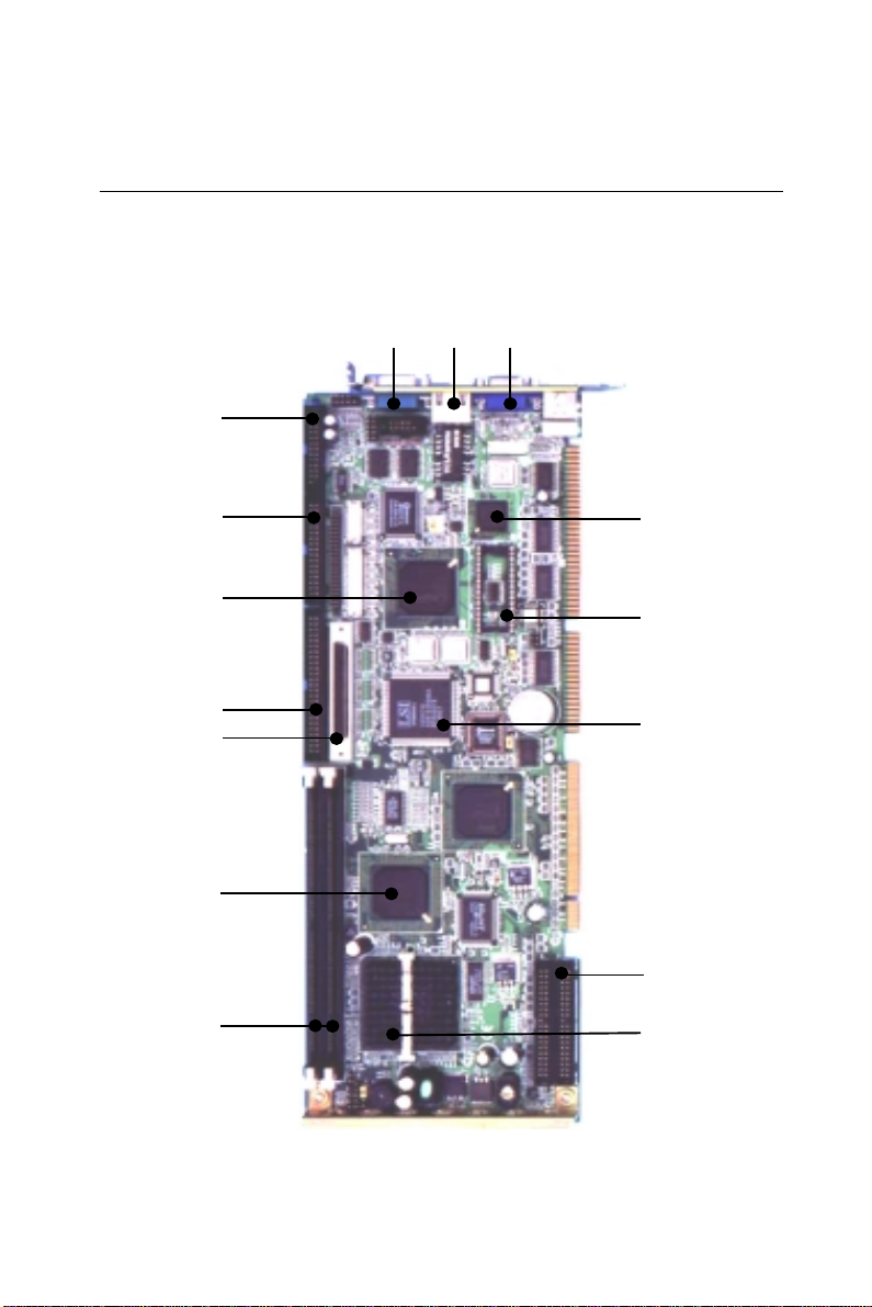
1.4 Board Layout: Main Features
COM1
LAN connecor
VGA connector
Parallel port
FDD
connector
C&T 69000
VGA chipset
82559ER
®
LAN chipset
Intel
2000SYM53C875E
®
DOC
connectors
Ultra Wide SCSI
430TX
®
chipset
Intel
(up to 256 MB)
2 DIMM sockets
Figure 1-1: PCA-6359 Series board layout: dimensions
Chapter 1 Hardware Configuration
SCSI chipset
EIDE connector
®
Pentium
®
MMX 266 CPU
Intel
7
Page 17

1.5 Safety Precautions
Follow these simple precautions to protect yourself from harm and
your PC from damage.
1. To avoid electric shock, always disconnect the power from your
PC chassis before you work on it. Do not touch any components
on the CPU card or other cards while the PC is on.
2. Disconnect power before making any configuration changes. The
sudden rush of power as you connect a jumper or install a card
may damage sensitive electronic components.
3. Always ground yourself to remove any static charge before you
touch your CPU card. Be particularly careful not to touch the chip
connectors. Modern integrated electronic devices, especially CPUs
and memory chips, are extremely sensitive to static electric
discharges and fields. Keep the card in its antistatic packaging
when it is not installed in the PC, and place it on a static dissipative mat when you are working with it. Wear a grounding wrist
strap for continuous protection.
8
PCA-6359 Series User's Manual
Page 18
1.6 Jumper Settings
This section tells how to set the jumpers to configure your card. It
gives the card default configuration and your options for each jumper.
After you set the jumpers and install the card, you will also need to
run the BIOS Setup program (discussed in Chapter 3) to configure the
serial port addresses, floppy/hard disk drive types and system operating parameters. Connections, such as hard disk cables, appear in
Chapter 2.
For the locations of each jumper, see the board layout diagram
depicted earlier in this chapter.
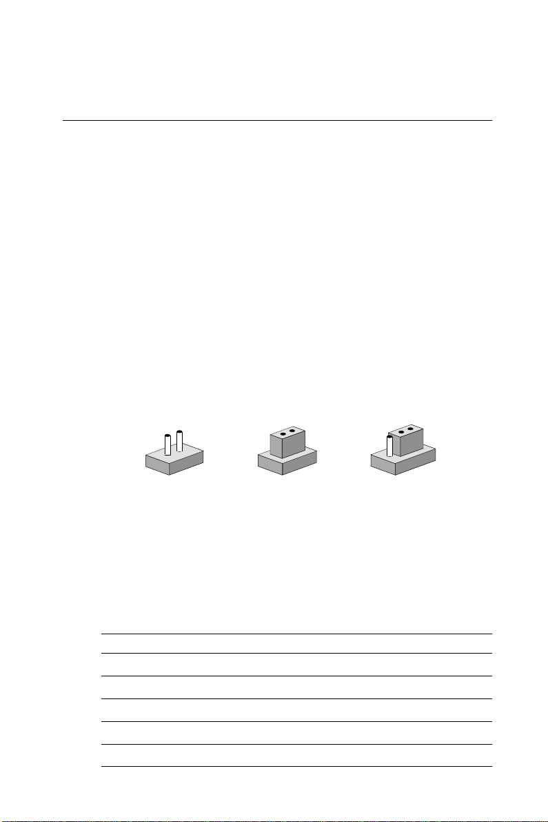
You configure your card to match the needs of your application by
setting jumpers. A jumper is a metal bridge that closes an electrical
circuit. It consists of two metal pins and a small metal cap (often
protected by a plastic cover) that slides over the pins to connect them.
To "close" a jumper you connect the pins with the cap. To "open" a
jumper you remove the cap. Sometimes a jumper will have three pins,
labeled 1, 2 and 3. In this case you connect either pins 1 and 2 or 2 and
3.
2
1
3
OpenOpen
Open
OpenOpen
ClosedClosed
Closed
ClosedClosed
Closed 2-3Closed 2-3
Closed 2-3
Closed 2-3Closed 2-3
You may find a pair of needle-nose pliers useful for setting the
jumpers.
If you have any doubts about the best hardware configuration for your
application, contact your local distributor or sales representative
before you make any changes.
Table 1-1: Jumpers
Label Function
J1 CMOS clear
J2 Watchdog timer output
J3 DiskOnChip® 2000 address setting
J4 44-pin LCD power select (Reserved)
Chapter 1 Hardware Configuration
9
Page 19
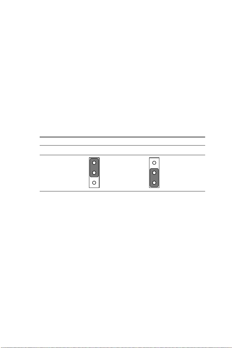
1.6.1 Clear CMOS (J1)
Warning: To avoid damaging the computer, always turn off the
power supply before setting "Clear CMOS". Set the
jumper back to normal before turning on the power
supply.
To clear the RTC data:
1. Turn off the computer and unplug the AC power.
2. Short the 2-3 pins.
3. Hold down <Delete> during boot-up and enter the BIOS setup to
re-enter your preferences.
Table 1-1: Clear CMOS (J1)
*Normal CMOS data clear
11
J1
* default setting
1.6.2 Watchdog output (J2)
An onboard watchdog timer reduces the chance of disruptions which
EMP (electro-magnetic pulse) interference can cause. This is an
invaluable protective device for standalone or unmanned applications.
Setup involves two jumpers and running the control software. (Refer
to Appendix A.)
When the watchdog timer is enabled and the CPU shuts down, the
watchdog timer will automatically either reset the system or generate
an interrupt on IRQ 11, depending on the setting of jumper JP4, as
shown below:
10
PCA-6359 Series User's Manual
Page 20
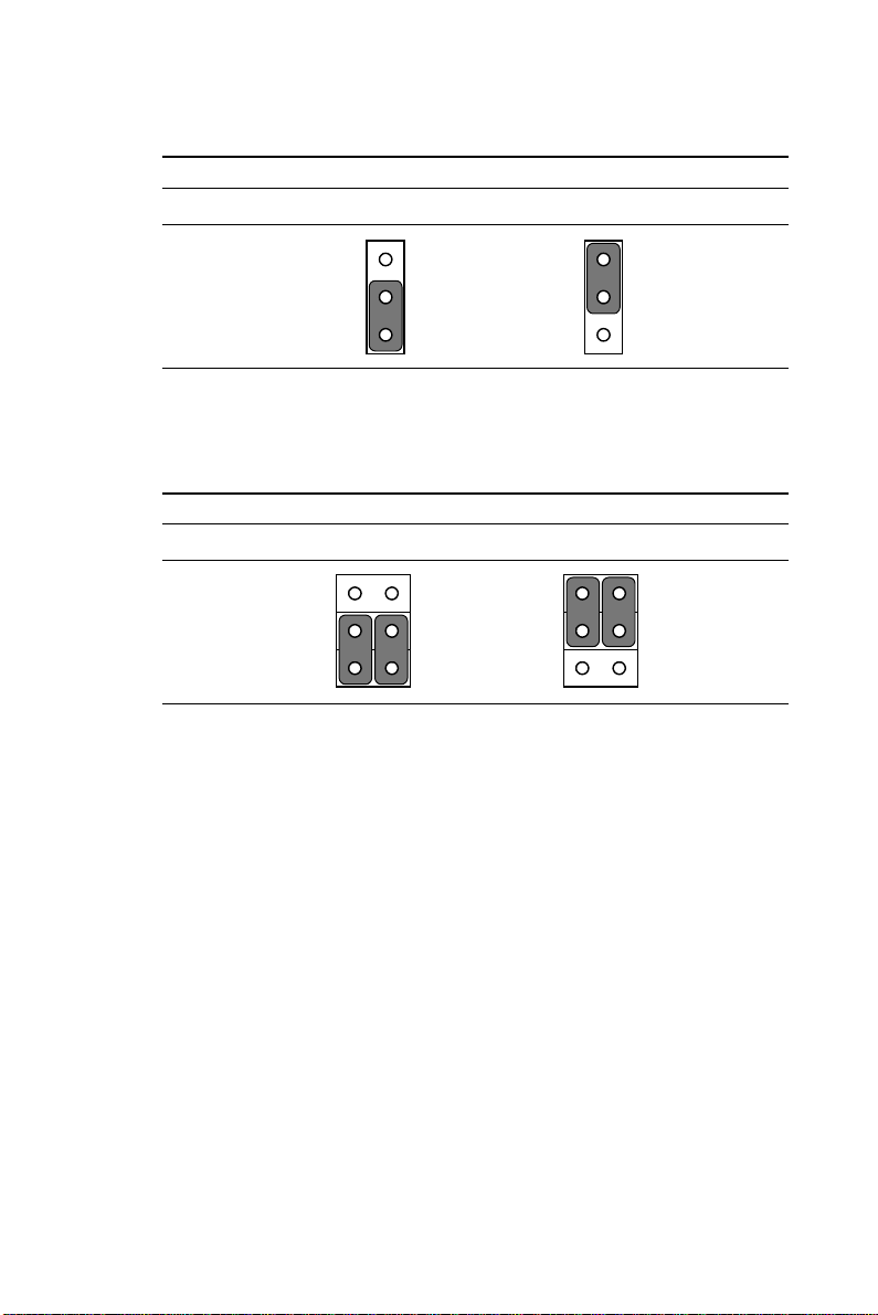
Table 1-2: Watchdog output (J2)
*System reset IRQ11 interrupt
1 1
J2
* default setting
1.6.3 44-pin LCD power select (J4)
Table 1-3: 44-pin LCD power select (J4)
*5 V 3.3 V
J4
* default setting
1
3
5
2
4
6
1
3
5
2
4
6
Chapter 1 Hardware Configuration
11
Page 21

1.6.4 DiskOnChip® 2000 Flash disk address select (J3)
The PCA-6359 Series includes a 32-pin socket for M-Systems'
DiskOnChip® 2000 Flash disk module. This revolutionary solid state
disk enables critical system information to be stored within an
onboard Flash disk for virtually instantaneous data access.
You must specify the memory address you want to use for your
DiskOnChip 2000 Flash disk module by setting jumper (J3). Available settings are shown in the following table.
12
PCA-6359 Series User's Manual
Page 22
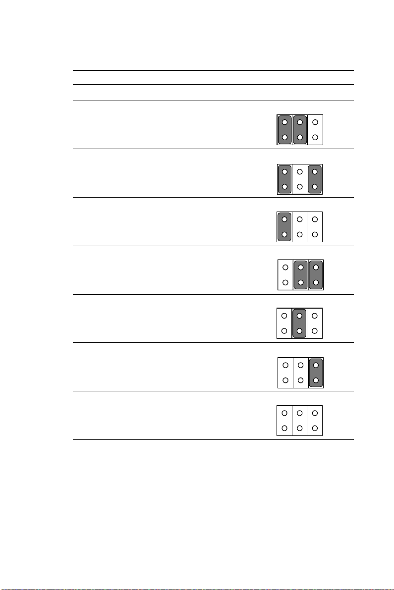
Table 1-4: DiskOnChip® 2000 Flash disk memory address jumper settings (J3)
Segment A B C
ABC
CC00h ON ON OFF
ABC
D000h ON OFF ON
ABC
D400h ON OFF OFF
ABC
D800h OFF ON ON
ABC
DC00h OFF ON OFF
ABC
E000h OFF OFF ON
Disable OFF OFF OFF
Chapter 1 Hardware Configuration
ABC
13
Page 23

1.7 System Memory
The top-left edge of the PCA-6359 Series contains three sockets for
168-pin dual inline memory modules (DIMMs). All three sockets use
3.3 V unbuffered synchronous DRAMs (SDRAM). DIMMs are
available in capacities of 16, 32, 64, or 128 MB. The sockets can be
filled in any combination with DIMMs of any size, giving your
PCA-6359 Series single board computer between 16 MB and 256 MB
of memory. Use the following table to calculate the total DRAM
memory within your computer:
Table 1-5: DIMM module allocation table
Socket number 168-pin DIMM memory
1 (16, 32, 64, or 128 MB) x 1
2 (16, 32, 64, or 128 MB) x 1
1.7.1 Sample calculation: DIMM memory capacity
Suppose you install a 128 MB DIMM into your PCA-6359 Series'
socket 1 and a 32 MB DIMM into socket 2. Your total system
memory is 160 MB, calculated as follows:
Table 1-6: DIMM memory capacity sample calculation
Socket number 168-pin DIMM memory Total memory
1 128 MB x 1 128 MB
2 32 MB x 1 32 MB
Total memory 160 MB
14
PCA-6359 Series User's Manual
Page 24

1.7.2 Supplementary information about DIMMs
Your PCA-6359 Series can accept SDRAM memory chips (with or
without parity). Also note:
• SDRAM chips are usually thinner and have higher pin density than
EDO chips.
• Modules with 9 chips/side support ECC; modules with 8 chips/side do not
support ECC.
• Single-sided modules are typically 16, 32 or 64 MB; double-sided
modules are usually 32, 64, or 128 MB.
1.8 Memory Installation Procedures
To install DIMMs, first make sure the two handles of the DIMM
socket are in the "open" position. i.e. The handles lean outward.
Slowly slide the DIMM module along the plastic guides on both ends
of the socket. Then press the DIMM module right down into the
socket, until you hear a click. This is when the two handles have
automatically locked the memory module into the correct position of
the DIMM socket. To remove the memory module, just push both
handles outward, and the memory module will be ejected by the
mechanism in the socket.
Chapter 1 Hardware Configuration
15
Page 25

16
PCA-6359 Series User's Manual
Page 26

CHAPTER
2
Connecting
Peripherals
This chapter tells how to connect
peripherals, switches and indicators to the
PCA-6359 Series board. You can access
most of the connectors from the top of the
board while it is installed in the chassis. If
you have a number of cards installed, or
your chassis is very tight, you may need
to partially remove the board to make all
the connections.
Page 27
2.1 Board Layout: Connector Locations
18
PCA-6359 Series User's Manual
Page 28

The following table lists the connectors on the PCA-6359 Series.
Table 2-1: Connectors
Number Function
CN1 Primary IDE connector
CN2 Secondary IDE connector
CN3 Floppy drive connector
CN4 Parallel port
CN5 Ultra Wide SCSI connector
CN6 USB port
CN7 VGA connector
CN8 10/100Base-T Ethernet connector
CN9 Serial port: COM1
CN10 Serial port: COM2
CN11 PS/2 keyboard and mouse
CN12 External keyboard connector
CN13 Infrared (IR) connector
CN16 Keyboard lock and power LED
CN17 External speaker
CN18 Reset connector
CN19 IDE LED
CN20 ATX feature connector
CN21 ATX soft power switch
CN23 LCD connector (Reserved)
CN24 LCD 24-bit LCD display connector
CN25 LCD 36-bit LCD display connector
CN26 Reserved
CN27 Ultra SCSI connector
Chapter 2 Connecting Peripherals
19
Page 29

The following sections tell how to make each connection. In most
cases, you will simply need to connect a standard cable. All of the
connector pin assignments are shown in Appendix B.
Warning! Always completely disconnect the power cord from
your chassis whenever you are working on it. Do not
make connections while the power is on. Sensitive
electronic components can be damaged by a
sudden rush of power. Only experienced electronics
personnel should open the PC chassis.
Caution! Always ground yourself to remove any static charge
before touching the CPU card. Modern electronic
devices are very sensitive to static electric charges.
Use a grounding wrist strap at all times. Place all
electronic components on a static-dissipative
surface or in a static-shielded bag when they are not
in the chassis.
20
PCA-6359 Series User's Manual
Page 30

2.2 Primary (CN1) and Secondary (CN2) IDE Connectors
You can attach up to four IDE (Integrated Device Electronics) drives
to the PCA-6359 Series' internal controller. The primary (CN1) and
secondary (CN2) connectors can each accommodate two drives.
Wire number 1 on the cable is red or blue and the other wires are
gray. Connect one end to connector CN1 or CN2 on the CPU card.
Make sure that the red/blue wire corresponds to pin 1 on the connector (in the upper right hand corner). See Chapter 1 of this manual for
help finding the connector.
Unlike floppy drives, IDE hard drives can connect in either position
on the cable. If you install two drives to a single connector, you will
need to set one as the master and one as the slave. You do this by
setting the jumpers on the drives. If you use just one drive per
connector, you should set each drive as the master. See the documentation that came with your drive for more information.
Connect the first hard drive to the other end of the cable. Wire 1 on
the cable should also connect to pin 1 on the hard drive connector,
which is labeled on the drive circuit board. Check the documentation
that came with the drive for more information.
Connect the second hard drive to the remaining connector (CN2 or
CN1), in the same way as described above.
Chapter 2 Connecting Peripherals
21
Page 31
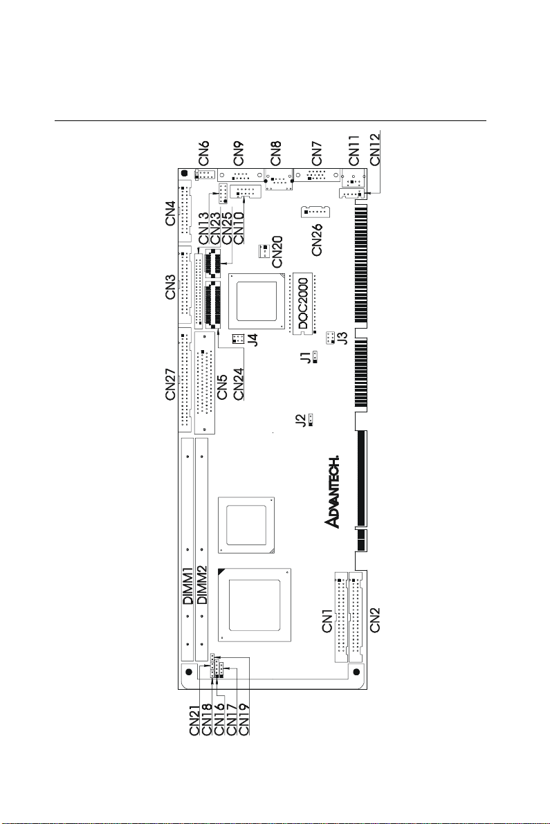
2.3 Floppy Drive Connector (CN3)
You can attach up to two floppy disk drives to the PCA-6359 Series'
onboard controller. You can use any combination of 5.25" (360 KB /
1.2 MB) and/or 3.5" (720 KB / 1.44/2.88 MB) drives.
The card comes with a 34-pin daisy-chain drive connector cable. On
one end of the cable is a 34-pin flat-cable connector. On the other end
are two sets of floppy disk drive connectors. Each set consists of a
34-pin flat-cable connector (usually used for 3.5" drives) and a printed
circuit-board connector (usually used for 5.25" drives). You can use
only one connector in each set. The set on the end (after the twist in
the cable) connects to the A: floppy drive. The set in the middle
connects to the B: floppy drive.
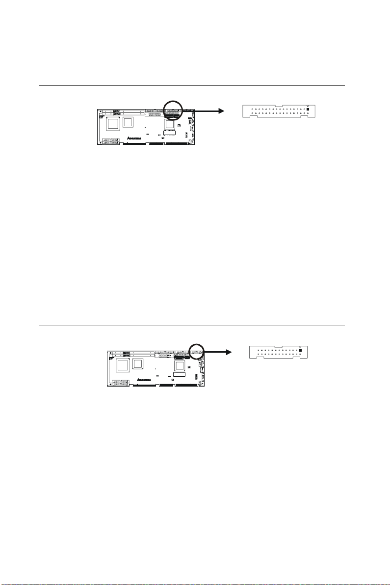
2.4 Parallel Port Connector (CN4)
The parallel port is normally used to connect the CPU card to a
printer. The PCA-6359 Series includes an onboard parallel port,
accessed through a 26-pin flat-cable connector, CN4. The card comes
with an adapter cable which lets you use a traditional DB-25 connector. The cable has a 26-pin connector on one end and a DB-25
connector on the other, mounted on a retaining bracket. The bracket
installs at the end of an empty slot in your chassis, giving you access
to the connector.
The parallel port is designated as LPT1, and can be disabled or
changed to LPT2 or LPT3 in the system BIOS setup.
22
PCA-6359 Series User's Manual
Page 32
To install the bracket, find an empty slot in your chassis. Unscrew the
plate that covers the end of the slot. Screw in the bracket in place of
the plate. Next, attach the flat-cable connector to CN4 on the CPU
card. Wire 1 of the cable is red or blue, and the other wires are gray.
Make sure that wire 1 corresponds to pin 1 of CN4. Pin 1 is on the
upper right side of CN4.
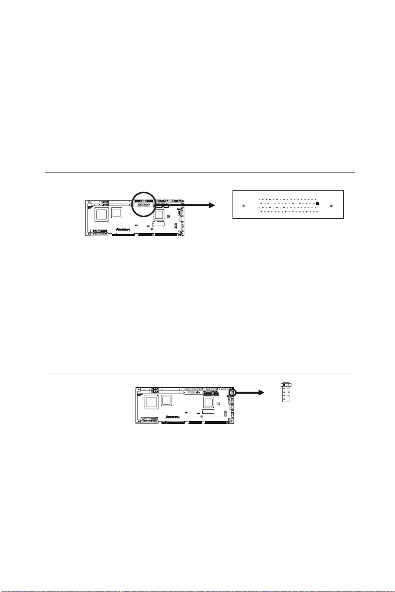
2.5 Ultra Wide SCSI Connector (CN5)
Note: Only the PCA-6359F model contains an Ultra Wide
SCSI connector.
The PCA-6359F has a 68-pin, dual inline connector for Ultra Wide
SCSI devices. Connection of SCSI devices requires special attention,
especially when determining the last drive on the SCSI chain. Refer to
Chapter 6 and your device's operating manual for detailed installation
advice.
2.6 USB Connector (CN6)
The PCA-6359 Series CPU card provides one USB (Universal Serial
Bus) interface, which give complete Plug & Play and hot
attach/detach for up to 127 external devices.The USB interface
complies with USB Specification Rev. 1.0, and is fuse-protected.
The USB interface is accessed through a 10-pin flat-cable connector,
CN6. The adapter cable has a 10-pin connector on one end and a USB
connector on the bracket.
The USB interface can be disabled in the system BIOS setup.
Chapter 2 Connecting Peripherals
23
Page 33

2.7 VGA Connector (CN7)
Note: Only the PCA-6359V/VE/F models include an
on-board VGA connector.
The PCA-6359V/VE/F includes a PCI SVGA interface that can drive
conventional CRT displays. CN7 is a standard 15-pin D-SUB connector commonly used for VGA. Pin assignments for CRT connector
CN7 are detailed in Appendix B of this manual.
2.8 Ethernet Connector (CN8)
Note: Only the PCA-6359VE/F models include a
10/100Base-T Ethernet connector.
The PCA-6359VE/F is equipped with a high performance 32-bit
PCI-bus Ethernet interface, which is fully compliant with IEEE
802.3/u 10/100 Mbps CSMA/CD standards. It is supported by all
major network operating systems, and is 100% Novell NE-2000
compatible. An onboard RJ-45 jack provides convenient
10/100Base-T RJ-45 operation.
24
PCA-6359 Series User's Manual
Page 34

2.9 Serial Ports (CN9: COM1; CN10: COM2)
The PCA-6359 Series offers two serial ports, CN9 as COM1 and
CN10 as COM2. These ports can connect to serial devices (such as a
mouse, printers, and so on) or to a communication network.
Table 2-2: Serial port connections (COM1, COM2)
Connector Ports Address Interrupt
CN9 COM1 3F8*, 3E8 IRQ4
CN10 COM2 2F8*, 2E8 IRQ3
* default settings
The IRQ and address ranges for both ports are fixed. However, if you
want to disable the port or change these parameters later, you can do
this in the system BIOS setup.
Different devices implement the RS-232 standard in different ways. If
you are having problems with a serial device, be sure to check the pin
assignments for the connector.
Chapter 2 Connecting Peripherals
25
Page 35

2.10 PS/2 Keyboard and Mouse Connector (CN11)
The PCA-6359 Series board provides a keyboard connector. A 6-pin
mini-DIN connector (CN11) on the card mounting bracket supports
single-board computer applications. The card comes with an adapter
to convert from the 6-pin mini-DIN connector to a standard DIN
connector and to a PS/2 mouse connector.
2.11 External Keyboard Connector (CN12)
In addition to the PS/2 mouse/keyboard connector on the PCA-6359
Series' rear plate, there is also an extra onboard external keyboard
connector. This gives system integrators greater flexibility in designing their systems.
2.12 IR Connector (CN13)
This connector supports the optional wireless infrared transmitting
and receiving module. This module mounts on the system case. You
must configure the setting through the BIOS setup (see Chapter 3).
26
PCA-6359 Series User's Manual
Page 36

2.13 Front Panel Connectors (CN16, CN17, CN18, CN19 and CN21)
There are several external switches to monitor and control the
PCA-6359 Series.
2.13.1 Keyboard lock and power on LED (CN16)
CN16 is a 5-pin connector for the keyboard lock and power on LED.
Refer to Appendix B for detailed information on the pin assignments.
If a PS/2 or ATX power supply is used, the system's power LED status
will be as indicated below:
Table 2-2: PS/2 or ATX power supply LED status
Power mode LED (PS/2 power) LED (ATX power)
System On On On
System Suspend Fast flashes Fast flashes
System Off Off Slow flashes
2.13.2 External speaker (CN17)
CN17 is a 4-pin connector for an extenal speaker. If there is no
external speaker, the PCA-6359 Series provides an onboard buzzer as
an alternative. To enable the buzzer, set pins 3-4 as closed.
2.13.3 Reset (CN18)
Many computer cases offer the convenience of a reset button. Connect
the wire from the reset button to CN18.
2.13.4 IDE LED (CN19)
You can connect an LED to connector CN19 to indicate when the
HDD is active.
Chapter 2 Connecting Peripherals
27
Page 37

2.13.5 ATX soft power switch (CN21)
If your computer case is equipped with an ATX power supply, you
should connect the power on/off button on your computer case to
CN21. This connection enables you to turn your computer on and off.
2.14 ATX Power Control Connectors (CN20 and CN21)
Note: Refer to the diagram on the previous page for the
location of CN21.
2.14.1 ATX feature connector (CN20) and soft power switch connector (CN21)
The PCA-6359 Series can support an advanced soft power switch
function if an ATX power supply is used. To enable the soft power
switch function:
1. Take the specially designed ATX-to-PS/2 power cable out of the
PCA-6359 Series' accessory bag.
2. Connect the 3-pin plug of the cable to CN20 (ATX feature
connector).
3. Connect the power on/off button to CN21. (A momentary type of
button should be used.)
Note: If you will not be using an ATX power connector,
make sure that pins 2-3 are closed.
28
PCA-6359 Series User's Manual
Page 38

Warnings: 1. Make sure that you unplug your power supply
when adding or removing expansion cards or other
system components. Failure to do so may cause
severe damage to both your CPU card and expansion cards.
2. ATX power supplies may power on if certain
motherboard components or connections are
touched by metallic objects.
Important: Make sure that the ATX power supply can take at
least a 720 mA load on the 5 V standby lead (5VSB).
If not, you may have difficulty powering on your
system and/or supporting the "Wake on LAN"
function.
2.14.2 Controlling the soft power switch
Users can also identify the current power mode through the system's
power LED (see Section 2.13.1).
2.15 LCD Inverter Connector (CN23)
CN23 consists of a 44-pin dual inline header.
The PCA-6359 Series provides a bias control signal that can be used
to control the LCD bias voltage. It is recommended that the LCD bias
voltage not be applied to the panel until the logic supply voltage (+5
V or +3.3 V) and panel video signals are stable. Under normal
operation, the control signal (ENAVEE) is active high. When the
PCA-6359 Series' power is applied, the control signal is low until just
after the relevant flat panel signals are present.
Chapter 2 Connecting Peripherals
29
Page 39
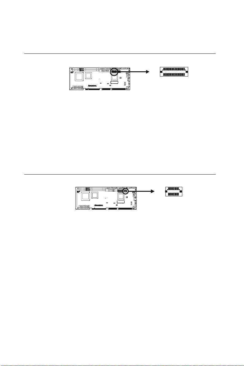
2.16 24-bit LCD Display Connector (CN24)
CN24 is a 40-pin dual inline header and is used to connect an LCD
display to the PCA-6359 Series. The PCA-6359 Series has bias
control which can be used to control the LCD signal voltage. Pin 7 of
CN24 is for LCD contrast adjustments The LCD contrast can be
adjusted via the BIOS.
The VGA interface is done completely with the softare utiliity
provided, please refer to Chapter 4 for details.
2.17 36-bit LCD Display Connector (CN25)
The PCA-6359 Series supports a 36-bit LCD that must be connected
to both CN24 (40-pin) and CN25 (20-pin).
The pin assignments for both CN24 and CN25 can be found in
Appendix B.
Warning! Before making the connection, make sure the
voltage is absolutely correct and matched with the
correct connector.
30
PCA-6359 Series User's Manual
Page 40

2.18 Ultra SCSI Connector (CN27)
The PCA-6359F has a 50-pin dual inline connector for Ultra SCSI
devices. Refer to Chapter 6 and your device's operating manual for
detailed installation advice.
Chapter 2 Connecting Peripherals
31
Page 41

32
PCA-6359 Series User's Manual
Page 42

CHAPTER
3
Award BIOS Setup
This chapter describes how to set the
card’s BIOS configuration data.
Page 43
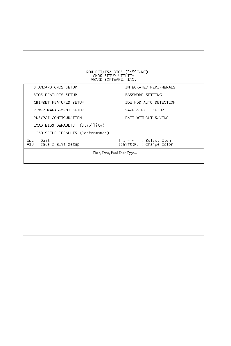
3.1 Introduction
Figure 3-1: Setup program initial screen
Award’s BIOS ROM has a built-in Setup program that allows users to
modify the basic system configuration. This type of information is
stored in battery-backed RAM so that it retains the Setup information
when the power is turned off.
3.2 Entering Setup
Turning on the computer and pressing <DEL> immediately will allow
you to enter Setup.
34
PCA-6359 Series User's Manual
Page 44

3.3 Standard CMOS Setup
Choose the “STANDARD CMOS SETUP” option from the INITIAL
SETUP SCREEN Menu, and the screen below is displayed. This
standard Setup Menu allows users to configure system components
such as date, time, hard disk drive, floppy drive, display, and memory.
Figure 3-2: CMOS setup screen
3.3.1 CMOS RAM backup
The CMOS RAM is powered by an onboard button cell battery.
When BIOS CMOS Setup has been completed, CMOS RAM data is
automatically backed up to Flash ROM. If conditions in a harsh
industrial enviroment cause a soft error, BIOS will recheck the data
and automatically restore the original data for booting.
Note: If you intend to update CMOS RAM data, you have
to click on “DEL” within two seconds of the “CMOS
checksum error....” display screen message appear-
ing. Then enter the “Setup” screen to modify the
data.
If the “CMOS checksum error....” message appears
again and again, please check to see if you need to
replace the battery in your system.
Chapter 3 Award BIOS Setup
35
Page 45

3.4 BIOS Features Setup
The “BIOS FEATURES SETUP” screen appears when choosing the
BIOS FEATURES SETUP item from the CMOS SETUP UTILITY
Menu. It allows the user to configure the PCA-6359 Series according
to his particular requirements.
Below are some major items that are provided in the BIOS FEATURES SETUP screen:
Figure 3-3: BIOS features setup screen
3.4.1 Virus Warning
During and after the system boots up, any attempt to write to the boot
sector or partition table of the hard disk drive will halt the system. In
this case, a warning message will be displayed. You can run the
anti-virus program to locate the problem.
If Virus Warning is Disabled, no warning message will appear if
anything attempts to access the boot sector or hard disk partition.
36
PCA-6359 Series User's Manual
Page 46

3.4.2 CPU Internal Cache/External Cache
Depending on the CPU/chipset design, these options can speed up
memory access when enabled.
3.4.3 Boot Sequence
This function determines the sequence in which the computer will
search the drives for the disk operating system (i.e. DOS). The default
value is “C, A”.
A,C System will first search the FDD, then the HDD.
C,A System will first search the HDD, then the FDD.
C only System will only search the HDD.
• •
• •
• •
3.4.4 Boot Up Floppy Seek
During POST, BIOS will determine if the floppy disk drive installed is
40 or 80 tracks. 360 KB type is 40 tracks while 720 KB, 1.2 MB, and
1.44 MB are all 80 tracks.
Enabled BIOS searches the floppy drive to determine if it is 40 or 80
tracks. Note that BIOS cannot differentiate 720 KB, 1.2 MB,
and 1.44 MB type drives as they are all 80 tracks.
Disabled BIOS will not search for the floppy drive type by track
number. Note that there will not be any warning message if
the drive installed is 360 KB.
Chapter 3 Award BIOS Setup
37
Page 47

3.4.5 Boot Up NumLock Status
The default is “On”.
On Keypad boots up to number keys.
Off Keypad boots up to arrow keys.
3.4.6 Typematic Rate Setting
The typematic rate determines the characters per second accepted by
the computer. Typematic Rate setting enables or disables the typematic rate.
3.4.7 Typematic Rate (Char/Sec)
BIOS accepts the following input values (character/second) for
Typematic Rate: 6, 8, 10, 12, 15, 20, 24, 30.
3.4.8 Typematic Delay (msec)
When holding down a key, the Typematic Delay is the time interval
between the appearance of the first and second characters. The input
values (msec) for this category are: 250, 500, 750, 1000.
3.4.9 Security Option
This setting determines whether the system will boot if the password
is denied, while limiting access to Setup.
System The system will not boot, and access to Setup will be
denied if the correct password is not entered at the prompt.
Setup The system will boot, but access to Setup will be
denied if the correct password is not entered at the prompt.
Note: To disable security, select PASSWORD SETTING in
the main menu. At this point, you will be asked to
enter a password. Simply hit the <ENTER> key to
disable security. When security is disabled, the
system will boot, and you can enter Setup freely.
38
PCA-6359 Series User's Manual
Page 48

3.4.10 OS Select for DRAM>64 MB
This setting is under the OS/2 system.
3.4.11 PCI/VGA Palette Snoop
This determines whether or not MPEG ISA/VESA VGA cards can
work with PCI/VGA.
3.4.12 Video BIOS Shadow
This determines whether video BIOS will be copied to RAM, which is
optional according to the chipset design. When enabled, Video
Shadow increases the video speed.
3.4.13 C8000 - CFFFF Shadow/DC000-DFFFF Shadow
These determine whether optional ROM will be copied to RAM in
blocks of 16 KB.
Enabled Optional shadow is enabled.
Disabled Optional shadow is disabled.
Chapter 3 Award BIOS Setup
39
Page 49

3.5 Chipset Features Setup
By choosing the “CHIPSET FEATURES SETUP” option from the
INITIAL SETUP SCREEN Menu, the screen below is displayed. This
sample screen contains the manufacturer’s default values for the
PCA-6359 Series.
Figure 3-4: Chipset features setup screen
3.5.1 SDRAM (CAS Lat / RAS-to-CAS)
This allows you to select the CAS latency for all SDRAM cycles and
RAS# to CAS# delay.
2/2 Timing type.
3/3 Timing type.
40
PCA-6359 Series User's Manual
Page 50

3.5.2 DRAM Speculative Read
This is capable of allowing a DRAM read request to be generated
slightly before the address has been fully decoded. This can reduce all
read latencies.
The CPU will issue a read request, and included with this request is
the place (address) in memory where the desired data is to be found.
This request is received by the DRAM controller. When it is enabled,
the controller will isue the read command slightly before it has
finished determining the address.
The default is “Disabled”.
3.5.3 16 Bit I/O Recovery Time / 8 Bit I/O Recovery Time
Timing for 16-bit and 8-bit ISA cards respectively. Leave these on
their respective default settings.
3.5.4 Memory Hole At 15M-16M
Enabling this feature reserves 15 MB to 16 MB memory address
space for ISA expansion cards that specifically require this setting.
This makes memory from 15 MB and up unavailable to the system.
Expansion cards can only access memory up to 16 MB. The default
setting is “Disabled.”
Chapter 3 Award BIOS Setup
41
Page 51

3.6 Power Management Setup
The power management setup controls the CPU cards’ “green”
features. The following screen shows the manufacturer’s default.
Figure 3-5: Power management setup screen
3.6.1 Power Management
This option allows you to determine if the values in power management are disabled, user-defined, or predefined.
3.6.2 PM Control by APM
When enabled, an Advanced Power Management device will be
activated to enhance the Max. Power Saving mode and stop the CPU
internal clock.
If the Max. Power Saving is not enabled, this will preset to "No".
42
PCA-6359 Series User's Manual
Page 52

3.6.3 Video Off Method
This determines the manner in which the monitor is blanked.
V/H SYNC+ Blank This will cause the system to turn off the vertical and
horizontal synchronization ports and write blanks to the
video buffer.
Blank Screen This only writes blanks to the video buffer.
DPMS Initial display power management signaling.
3.6.4 MODEM Use IRQ
This determines the IRQ in which the MODEM can be used.
The default is “3”.
3.6.5 HDD Power Down
You can choose to turn the HDD off after a one of the time interval
listed, or when the system is in Suspend mode. If in a power saving
mode, any access to the HDD will wake it up.
Note: The HDD will not power down if the Power Manage-
ment option is disabled.
3.6.6 ZZ Active in Suspend
In this mode, SRAM will enter a low-power state.
3.6.7 PCI/VGA Act-Monitor
In you enable this option, any video activity will restart the global
timer for standby mode.
Chapter 3 Award BIOS Setup
43
Page 53

3.6.8 Soft-Off by PWR-BTTN
If you choose “Instant-Off”, then pushing the ATX soft power switch
button once will switch the system to “system off” power mode.
You can choose “Delay 4 sec.” If you do, then pushing the button for
more than 4 seconds will turn off the system, whereas pushing the
button momentarily (for less than 4 seconds) will switch the system to
“suspend” mode.
3.6.9 PowerOn by Ring
This allows either settings of Enabled or Disabled for powering up the
computer (i.e. turning on the ATX power supply) when the modem
receives a call while the computer is in Soft-Off mode.
Note: The computer cannot receive or transmit data until
the computer and applications are fully running.
Thus connection cannot be made on the first try.
Turning an external modem off and then back on
while the computer is off causes an initialization
string that will also cause the system to power on.
3.6.10 PowerOn by Alarm
This allows you to have an unattended or automatic power up of your
system. You may configure your system to power up at a certain time
and day.
44
PCA-6359 Series User's Manual
Page 54

3.7 PnP PCI Configuration Setup
Figure 3-6: PCI configuration screen
3.7.1 IRQ-xx assigned to : PCI/ISA PnP
These fields indicate whether or not the displayed IRQ for each field
is being used by a legacy (non-PnP) card. Two options are available:
PCI/ISA PnP or Legacy ISA. The first option, the default setting,
indicates that the displayed IRQ is not used to determine if an ISA
card is using that IRQ. If you install a legacy ISA card that requires a
unique IRQ, you must set the field for that IRQ to “Legacy ISA”. Say
for example that you install a legacy ISA card that requires IRQ10.
You must then set “IRQ-10 assigned to :” as “Legacy ISA”.
Chapter 3 Award BIOS Setup
45
Page 55

3.7.2 DMA-x assigned to : PCI/ISA PnP
These fields indicate whether or not the displayed DMA channel for
each field is being used by a legacy (non-PnP) card. Two options are
available: PCI/ISA PnP or Legacy ISA. The first option, the default
setting, indicates that the displayed DMA channel is not used to
determine if an ISA card is using that channel. If you install a legacy
ISA card that requires a unique DMA channel, you must set the field
for that channel to “Legacy ISA”.
3.8 Load BIOS Defaults
“LOAD BIOS DEFAULTS” indicates the most appropriate values for
the system parameters for minimum performance. These default
values are loaded automatically if the stored record created by the
Setup program becomes corrupted (and therefore unusable).
3.9 Load Setup Defaults
“LOAD SETUP DEFAULTS” loads the values required by the system
for maximum performance.
46
PCA-6359 Series User's Manual
Page 56

3.10 Integrated Peripherals
Figure 3-7: Integrated peripherals
3.10.1 IDE HDD Block Mode
If you enable IDE HDD Block Mode, the enhanced IDE driver will be
enabled. Leave IDE HDD Block Mode on the default setting.
3.10.2 IDE Primary Master/Slave PIO/UDMA Mode, IDE Secondary Master/Slave PIO/UDMA Mode (Auto)
Each channel (Primary and Secondary) has both a master and a slave,
making four IDE devices possible. Because each IDE device may
have a different Mode timing (0, 1, 2, 3, 4), it is necessary for these to
be independent. The default setting “Auto” will allow autodetection to
ensure optimal performance.
Chapter 3 Award BIOS Setup
47
Page 57

3.10.3 On-Chip PCI IDE Primary/Secondary
You can enable the Primary IDE channel and/or the Secondary IDE
channel. Any channel not enabled is disabled. This field is for systems
with only SCSI drives.
3.10.4 Onboard FDC Controller
When enabled, this field allows you to connect your floppy disk
drives to the on-board floppy disk drive connector instead of a
separate controller card. If you want to use a different controller card
to connect the floppy disk drives, set this field to Disabled.
3.10.5 Onboard Serial Port 1 (3F8H/IRQ4)
The settings are 3F8H/IRQ4, 2F8H/IRQ3, 3E8H/IRQ4, 2E8H/IRQ10,
and Disabled for the on-board serial connector.
3.10.6 Onboard Serial Port 2 (2F8H/IRQ3)
The settings are 3F8H/IRQ4, 2F8H/IRQ3, 3E8H/IRQ4, 2E8H/IRQ10,
and Disabled for the onboard serial connector.
3.10.7 UART Mode Select
The item allows you to determine the Infrared (IR) function of the
onboard I/O chip. The default setting is Normal.
3.10.8 UART2 Duplex Mode
You can select the IR function when your UART2 Mode is ASKIR.
3.10.9 RxD, TxD Active
This item allows you to determine the activity of RxD and TxD.
48
PCA-6359 Series User's Manual
Page 58

3.10.10 Onboard Parallel Port (378H/IRQ7)
This field sets the address of the on-board parallel port connector.
You can select either 3BCH/IRQ7, 378H/IRQ7, 278H/IRQ5 or
Disabled. If you install an I/O card with a parallel port, make sure
there is no conflict in the address assignments. The PCA-6359 Series
can support up to three parallel ports, as long as there are no conflicts
for each port.
3.10.11 Parallel Port Mode (ECP + EPP)
This field allows you to set the operation mode of the parallel port.
The setting “Normal” allows normal speed operation, but in one
direction only. “EPP” allows bidirectional parallel port operation at
maximum speed. “ECP” allows the parallel port to operate in bidirectional mode and at a speed faster than the maximum data transfer rate.
“ECP + EPP” allows normal speed operation in a two-way mode.
3.10.12 ECP Mode Use DMA
This selection is available only if you select “ECP” or “ECP + EPP”
in the Parallel Port Mode field. In ECP Mode Use DMA, you can
select DMA channel 1, DMA channel 3, or Disable. Leave this field
on the default setting.
Note: If you enable the IDE HDD block mode, the en-
hanced IDE driver will be enabled.
3.11 Password Setting
To change, confirm, or disable the password, choose the “PASSWORD SETTING” option form the Setup main menu and press
[Enter]. The password can be at most 8 characters long.
Remember, to enable this feature. You must first select the Security
Option in the BIOS FEATURES SETUP to be either “Setup” or
“System.” Pressing [Enter] again without typing any characters can
disable the password setting function.
Chapter 3 Award BIOS Setup
49
Page 59

3.12 IDE HDD Auto Detection
“IDE HDD AUTO DETECTION” automatically self-detects for the
correct hard disk type.
3.13 Save & Exit Setup
If you select this and press the [Enter] key, the values entered in the
setup utilities will be recorded in the CMOS memory of the chipset.
The microprocessor will check this every time you turn your system
on and compare this to what it finds as it checks the system. This
record is required for the system to operate.
3.14 Exit Without Saving
Selecting this option and pressing the [Enter] key lets you exit the
Setup program without recording any new values or changing old
ones.
50
PCA-6359 Series User's Manual
Page 60

CHAPTER
4
PCI SVGA Setup
(PCA-6359V/VE/F only)
• Introduction
• Installation of SVGA driver
- for Windows 95
- for Windows 98
- for Windows NT
• Further information
Page 61

4.1 Introduction
The PCA-6359V/VE/F has an onboard PCI flat panel/VGA interface.
The specifications and features are described as follows:
4.1.1 Chipset
The PCA-6359V/VE/F uses a C&T 69000 chipset for its PCI/SVGA
controller. It supports many popular LCD, EL, and gas plasma flat
panel displays and conventional analog CRT monitors. The 69000
VGA BIOS supports monochrome LCD, EL, color TFT and STN
LCD flat panel displays. In addition, it also supports interlaced and
non-interlaced analog monitors (color and monochrome VGA) in
high-resolution modes while maintaining complete IBM VGA
compatibility. Digital monitors (i.e. MDA, CGA, and EGA) are NOT
supported. Multiple frequency (multisync) monitors are handled as if
they were analog monitors.
4.1.2 Display memory
With onboard 2 MB display memory, the VGA controller can drive
CRT displays or color panel displays with resolutions up to 1024 x
768 at 64 K colors. The display memory can be expanded to 4 MB for
true-color resolution of 1024 x 768 with C&T 69030 upon request.
4.1.3 Display types
CRT and panel displays can be used simultaneously. The
PCA-6359V/VE/F can be set in one of three configurations: on a
CRT, on a flat panel display, or on both simultaneously. The system is
initially set to simultaneous display mode. The utility disks include
three *.COM files in the subdirectory Utility\vga\ which can be
used to configure the display. In order to use these configuration
programs, type the file name and path at the DOS prompt.
CT.COM: Enables CRT display only
FP.COM: Enables panel display only
SM.COM: Enables both displays simultaneously
52
PCA-6359 Series User's Manual
Page 62

4.2 Installation of SVGA Driver
Complete the following steps to install the SVGA driver. Follow the
procedures in the flow chart that apply to the operating system that
you you are using within your PCA-6359V/VE/F.
Important: The following windo ws illustrations are examples
only. You must follow the flow chart instructions and
pay attention to the instructions which then appear
on your screen.
Note: <Enter> means pressing the “Enter” key on the
keyboard.
4.2.1 Installation for Windows 95
The procedure is virtually identical to the procedure for installing
Windows 98. Refer to "Installation for Windows 98" on the next page,
and follow the procedure therein.
Chapter 4 PCI SVGA Setup (PCA-6359V/VE/F only)
53
Page 63
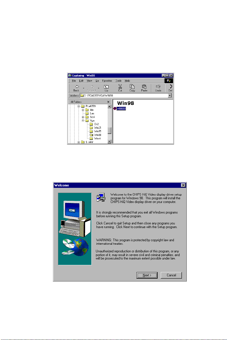
4.2.2 Installation for Windows 98
1. Insert the utility CD into drive D:. Navigate to
Pca6359\Vga\Win98\w98600. Double-click on "w98600".
2. In the "Welcome" window, make sure that all other Windows
programs have been exited. Then click on "Next".
54
PCA-6359 Series User's Manual
Page 64
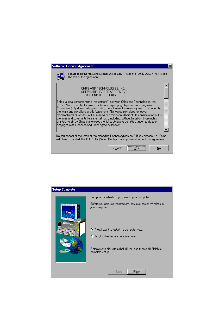
3. In the "Software License Agreement" window, carefully read the
"Software License Agreement". If you accept all the terms of this
Agreement, click on "Yes".
4. In the "Setup Complete" window, select "Yes, I want to ...". Then
click on "Finish".
Chapter 4 PCI SVGA Setup (PCA-6359V/VE/F only)
55
Page 65

5. In the "Chips and Tech. 69000 PCI Properties" window, select the
"Chips" tab. Then click on "OK".
56
PCA-6359 Series User's Manual
Page 66
4.2.3 Installation for Windows NT
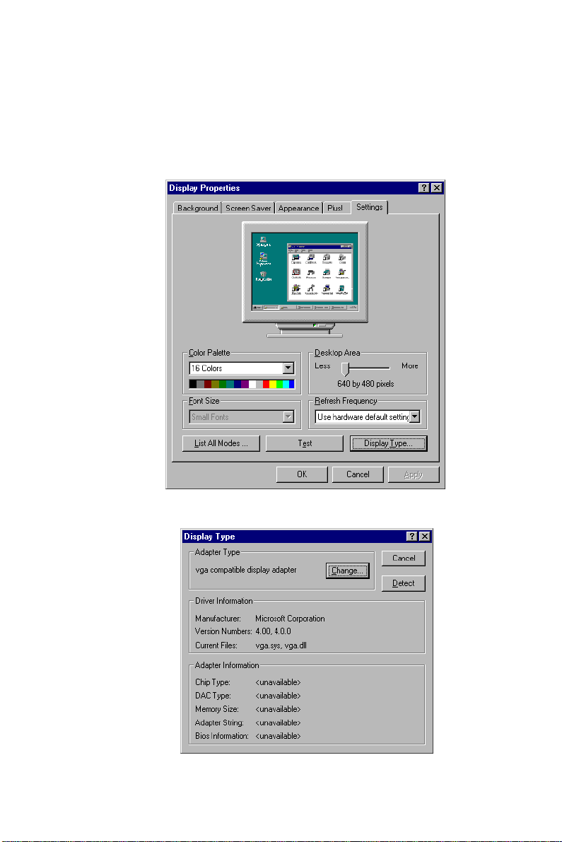
1. In the "Control Panel" screen, select the "Display" icon. In the
"Display Properties" window, select the "Settings" tab. Then click
on "Display Type...".
2. In the "Display Type" window, click on "Change...".
Chapter 4 PCI SVGA Setup (PCA-6359V/VE/F only)
57
Page 67
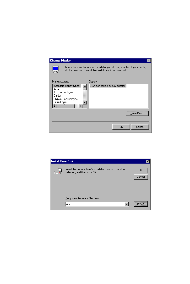
3. In the "Change Display" window, select "[Standard display
types]" under "Manufacturers:", and "VGA compatible display
adapter" under "Display". Then click on "Have Disk...".
4. In the "Install From Disk" window, click on "Browse...".
58
PCA-6359 Series User's Manual
Page 68

5. In the "Locate File" window, click on "Cancel". Using Windows
Explorer, navigate to: D:\PCA6359\vga\WINNT\Oemsetup.
Double-click on the "Oemsetup" file to open it.
6. In the "Install From Disk" window, click on "OK".
Chapter 4 PCI SVGA Setup (PCA-6359V/VE/F only)
59
Page 69

7. In the "Change Display" window, click on "OK".
8. In the "Third-party Drivers" window, click on "Yes".
9. In the "Installing Driver" window, click on "OK".
60
PCA-6359 Series User's Manual
Page 70
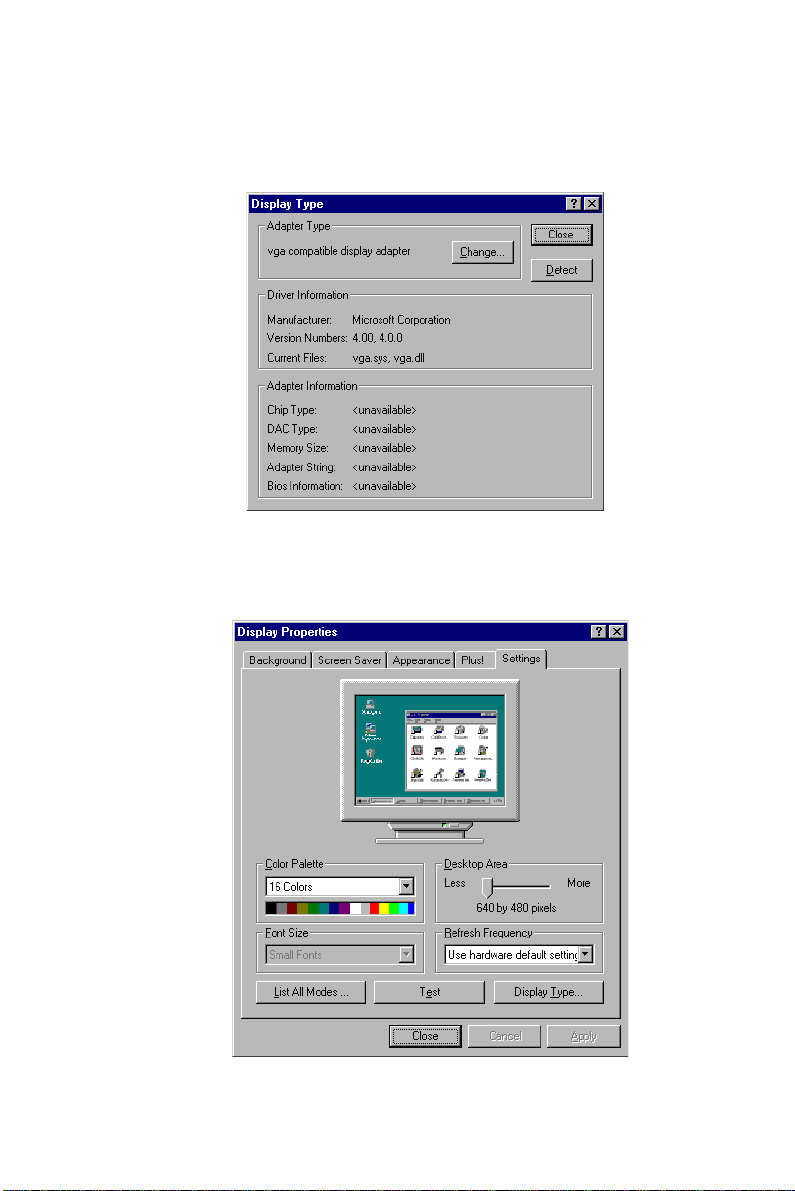
10. In the "Display Type" window, click on "Close".
11. In the "Display Properties" window, click on "Close".
Chapter 4 PCI SVGA Setup (PCA-6359V/VE/F only)
61
Page 71

12. In the "System Settings Change" window, click on "Yes".
62
PCA-6359 Series User's Manual
Page 72

CHAPTER
5
PCI Bus Ethernet
Interface
(PCA-6359VE/F only)
This chapter provides information on
Ethernet configuration.
• Introduction
• Installation of Ethernet driver
- for MS-DOS and Windows 3.1
- for Windows 95
- for Windows 98
- for Windows NT
• Further information
Page 73

5.1 Introduction
The PCA-6359VE/F is equipped with a high-performance 32-bit
Ethernet chipset which is fully compliant with IEEE 802.3 100 Mbps
CSMA/CD standards. It is supported by major network operating
systems. It is also both 100Base-T and 10Base-T compatible. The
medium type can be configured via the 82558.exe program included
on the utility disc.
The Ethernet port provides a standard RJ-45 jack. The network boot
feature can be utilized by incorporating the boot ROM image files for
the appropriate network operating system. The boot ROM BIOS files
are combined with system BIOS, which can be enabled/disabled in the
BIOS setup.
5.2 Installation of Ethernet Driver
Before installing the Ethernet driver, note the procedures below. You
must know which operating system you are using in your
PCA-6359VE/F, and then refer to the corresponding installation flow
chart. Then just follow the steps described in the flow chart. You will
quickly and successfully complete the installation, even if you are not
familiar with instructions for MS-DOS or Windows.
Note: The windows illustrations in this chapter are exam-
ples only. You must follow the flow chart instructions
and pay attention to the instructions which then
appear on your screen.
5.2.1 Installation for MS-DOS and Windows 3.1
If you want to set up your Ethernet connection under the MS-DOS or
Windows 3.1 environment, you should first check your server system
model. For example, MS-NT, IBM-LAN server, and so on.
Then choose the correct driver to install in your panel PC.
The installation procedures for various servers can be found in the
directory path "LAN/TXT/*" of the drivers and utilities disc, where *
is your server model.
64
PCA-6359 Series User's Manual
Page 74

5.2.2 Installation for Windows 95
The procedure is virtually identical to the procedure for installing
Windows 98. Refer to "Installation for Windows 98" on the next page,
and follow the procedure therein.
Chapter 5 PCI Bus Ethernet Interface (PCA-6359VE/F only)
65
Page 75
5.2.3 Installation for Windows 98
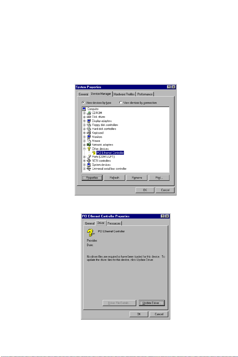
1. In the "Control Panel" screen, select the "System" icon. In the
"System Properties" window, select the "Device Manager" tab.
Navigate to: Other Devices/PCI Ethernet Controller. Highlight
"PCI Ethernet Controller". Then click on "Properties".
2. In the "PCI Ethernet Controller Properties" window, select the
"Driver" tab. Then click on "Update Driver...".
66
PCA-6359 Series User's Manual
Page 76

3. In the "Update Device Driver Wizard" window, click on "Next".
4. In the "Add New Hardware Wizard" window, select "Search for
the best driver ...". Then click on "Next".
Chapter 5 PCI Bus Ethernet Interface (PCA-6359VE/F only)
67
Page 77
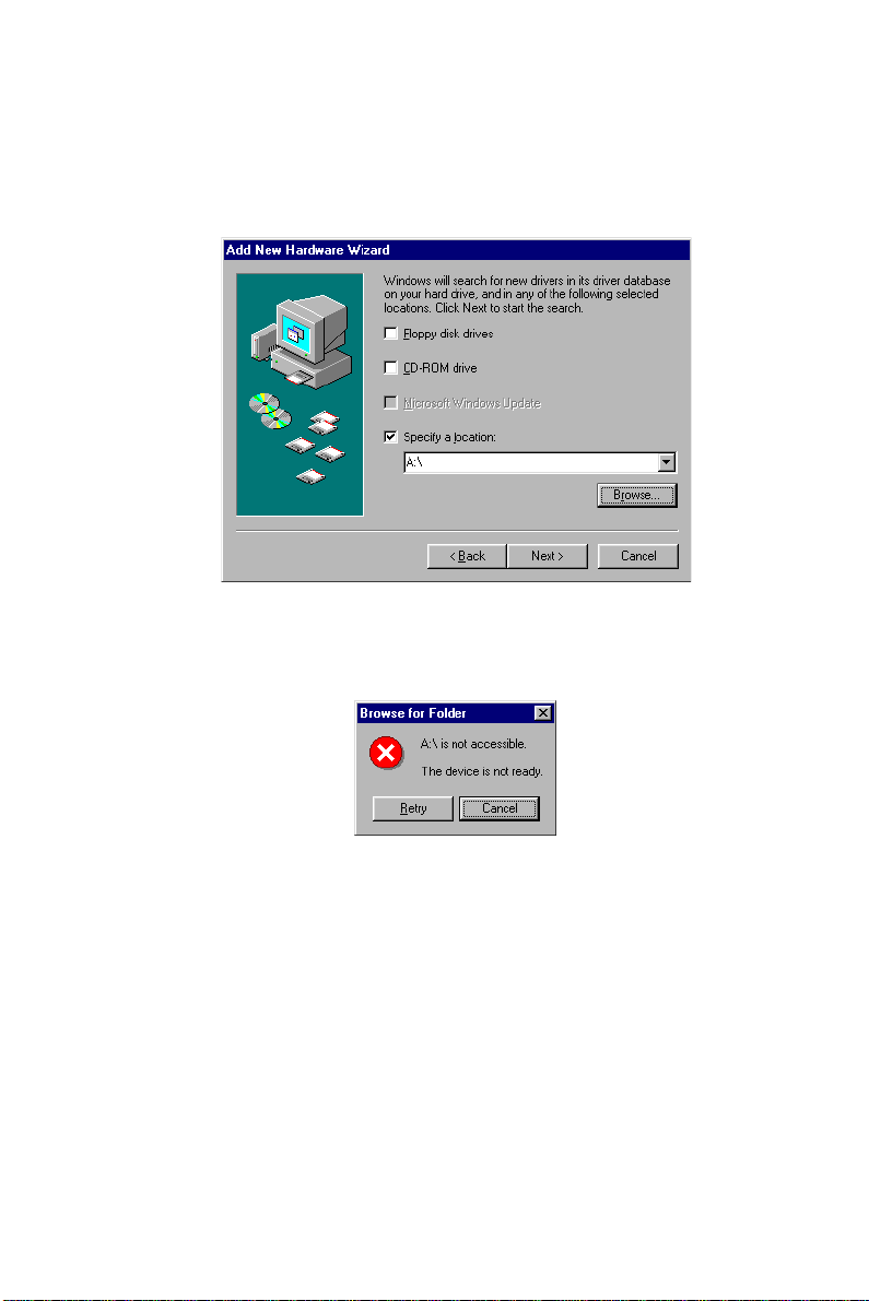
5. In the following "Add New Hardware Wizard" window, select
"Specify a location". Then click on "Browse...".
6. In the "Browse for Folder" window, click on "Cancel".
68
PCA-6359 Series User's Manual
Page 78
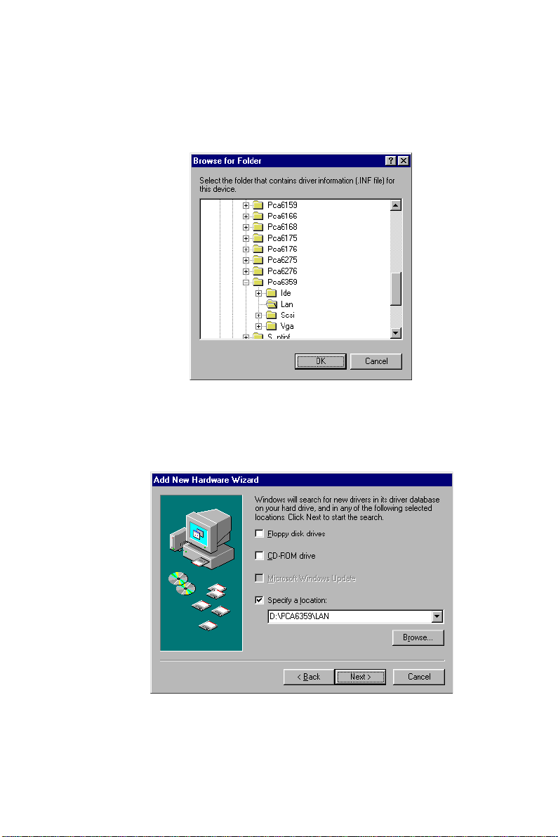
7. In the following "Browse for Folder" window, navigate to:
Pca6359/Lan. Highlight "Lan". Then click on "OK".
8. In the "Add New Hardware Wizard" window, select "Specify a
location:". Then click on "Next".
Chapter 5 PCI Bus Ethernet Interface (PCA-6359VE/F only)
69
Page 79
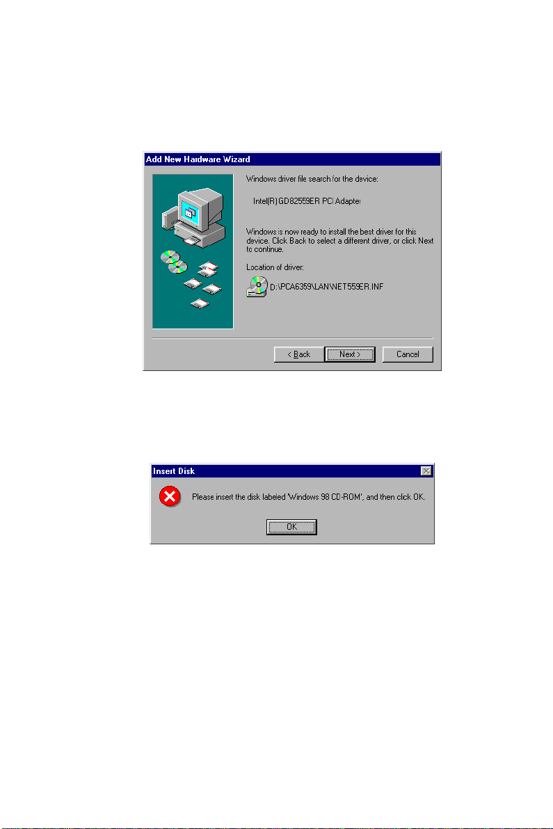
9. In the following "Add New Hardware Wizard" window, click on
"Next".
10. When the "Insert Disk" window appears, insert the utility disk
into the D: drive. Then click on "OK".
70
PCA-6359 Series User's Manual
Page 80

11. In the "Add New Hardware Wizard" window, click on "Finish".
12. In the "System Settings Change" window, click on "Yes".
Chapter 5 PCI Bus Ethernet Interface (PCA-6359VE/F only)
71
Page 81
5.2.4 Installation for Windows NT
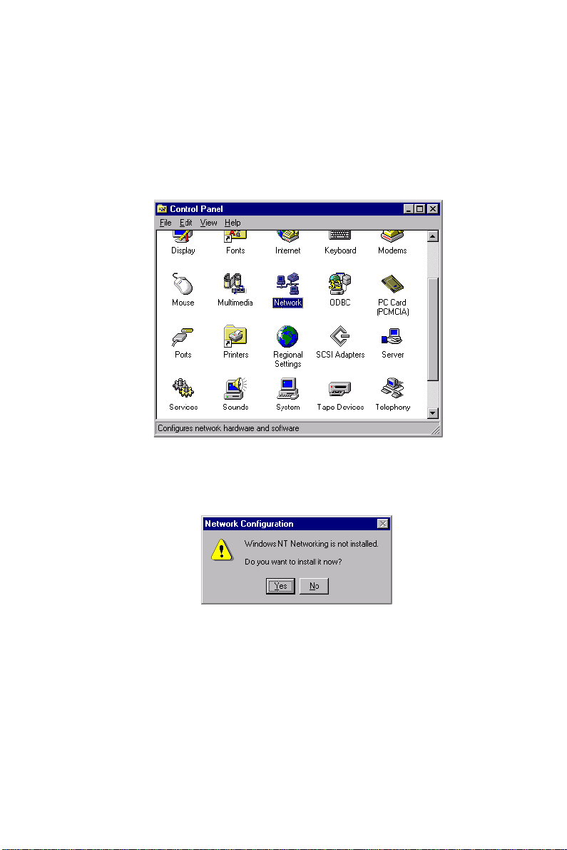
1. In the "Windows NT" screen, click "Start" and select "Settings".
Then click the "Control Panel" icon to select "Network".
Double-click on "Network".
2. In the "Network Configuration" window, click on "Yes".
72
PCA-6359 Series User's Manual
Page 82

3. In the "Network Setup Wizard" window, select "Wired to the
network:". Then click on "Next".
4. In the following "Network Setup Wizard" window, click on
"Select from list...".
Chapter 5 PCI Bus Ethernet Interface (PCA-6359VE/F only)
73
Page 83

5. In the "Select Network Adapter" window, click on "Have Disk...".
6. When the "Insert Disk" window appears, insert the utility
CD-ROM into the D: drive. Key in: D:\PCA6359\LAN. Then
click on "OK".
74
PCA-6359 Series User's Manual
Page 84

7. In the "Select OEM Option" window, click on "OK".
8. For the remainder of the installation procedure, simply follow the
further instructions which appear on screen. Continue to click on
"Next" until the installation is completed.
Chapter 5 PCI Bus Ethernet Interface (PCA-6359VE/F only)
75
Page 85

5.3 Further Information
Intel® website: www.intel.com
Advantech websites: www.advantech.com
support.advantech.com
76
PCA-6359 Series User's Manual
Page 86

CHAPTER
6
SCSI Setup and
Configurations
(PCA-6359F only)
The PCA-6359F features an onboard
SCSI interface. This chapter provides
basic SCSI concepts and instructions for
installing the software drivers with the
SCSI driver CD/disks included in your
package.
Page 87

6.1 Introduction
The PCA-6359F is equipped with a Symbios SYM53C875E
single-chip PCI-to-SCSI host adapter which provides a powerful Ultra
Wide multitasking interface between your computer’s PCI bus and
SCSI devices (disk drives, CD-ROM drives, scanners, tape backups,
removable media drives, etc.). Up to a total of 15 SCSI devices can be
connected to the SCSI connector through the Symbios SYM53C875E.
The Symbios SYM53C875E is a 16-bit single-ended SCSI solution
for your computer. It can support both legacy Fast SCSI and Ultra
SCSI devices, as well as the newest Ultra Wide SCSI devices.
If you need to configure the SCSI, the onboard SCSI Select configuration utility allows you to change host adapter settings without opening
the computer or handling the board. The SCSI Select utility also
contains a utility to low-level format and verifies the disk media on
your hard disk drives.
6.2 Before You Begin
SDMS software requires an IBM PC/AT or compatible computer with
an 80486 or higher microprocessor. An understanding of basic
operating system commands is assumed. In addition, users should
have a general knowledge of the SCSI standard.
Before using the SDMS software, you should configure the Symbios
SCSI controller into your system, taking into account the configuration of other host adapters and system resources (see Section 6.3).
Symbios recommends that you back up all data before making any
changes or installing any software, including the Symbios SCSI
controllers and software. Failure to adhere to this accepted computer
practice may lead to loss of data.
78
PCA-6359 Series User’s Manual
Page 88

6.3 Basic Rules for SCSI Host Adapter and Device Installation
You must terminate both ends of the SCSI bus. Refer to the hardware
manuals for the devices and the host adapter to properly terminate the
bus.
Unless your system is SCSI Configured AutoMatically (SCAM)
capable, you must configure each SCSI device with a different SCSI
ID number. Refer to the hardware manuals for the devices to locate
where the jumpers of dip switches are for setting SCSI ID numbers.
Usually, the host adapter is ID 7. The devices are then set at IDs 0
through 6 (plus 8 through 15 for Wide SCSI). The bootable hard drive
must have the lowest numerical SCSI ID, unless you are able to use
the BIOS Boot Specification (BBS).
The red or blue line on a standard SCSI cable (or the black line on one
end of a multi-colored SCSI cable) designates Pin One on the cable
connector, and must connect to Pin One on the device or host adapter
connector. Refer to Appendix B of this manual to find Pin One of the
connector.
6.4 Configuring the SCSI Adapter
Access the SCSI BIOS by holding down both the CTRL and C keys
when you see the BIOS banner message listing the driver name and
the attached devices. For example:
Symbios Inc. SDMS (TM) V 4.0 PCI SCSI BIOS
PCI Rev. 2.0, 2.1
Copyright 1995, 1998 Symbios Inc.
PCI-4.14.00
Press Ctrl-C to start Symbios Configuration
Utility...
The SCSI Select screen will come up. Instructions on how to move the
cursor and select options are listed on the bottom of the program
windows. You can select either Configure/View Host Adapter
Settings or SCSI CD Utilities.
Chapter 6 SCSI Setup and Configurations (PCA-6359F only)
79
Page 89

6.5 SCSI Terminators
To ensure reliable communication, the SCSI bus must be properly
terminated. Termination is controlled by a set of electrical resistors,
called terminators. Terminators must be placed (or enabled) at the two
extreme ends of the SCSI bus. All devices that lie between the ends
must have their terminators removed (or disabled).
Since the method for terminating a SCSI peripheral can vary widely,
refer to the peripheral’s documentation for instructions on how to
enable or disable termination. Here are some general guidelines for
termination:
• Termination on internal SCSI peripherals is usually controlled by
manually setting a jumper or switch on the peripheral, or by
physically removing or installing one or more resistor modules on
the peripheral.
• Termination on external SCSI peripherals is usually controlled by
installing or removing a SCSI terminator. On some external
peripherals, termination is controlled by setting a switch on the rear
of the drive.
• By default, termination on the CPU card itself is automatic (the
preferred method).
• Internal Ultra Wide peripherals are set at the factory with termination disabled, which cannot be changed. Proper termination for
internal Ultra Wide peripherals is provided by the built-in terminator at the end of the Ultra Wide internal SCSI cable.
• Most non-Ultra Wide SCSI peripherals come from the factory with
termination enabled.
80
PCA-6359 Series User’s Manual
Page 90

6.6 SDMS Drivers
The SDMS device drivers translate an operating system I/O request
into a SCSI request. Each Symbios SCSI device driver is operating
system specific and is designed to work on standard Symbios chip
implementations.
We provide PCI SDMS device drivers for the following operating
systems:
• MS-DOS/Windows
• Windows 95/98
• Windows NT - 3.51 and above
• OS/2 4.x Warp
• SCO UNIX - Open Server 5.0.2 and above
• Novell NetWare - 3.12, 4.11 (NWPA)
Note: When you start the Windows NT installation with
either a CD-ROM boot or from the floppy disks , a
black screen will initially appear with the f ollo wing
text at the top:
Setup is inspecting your computer’s
hardware configuration...
While this is on the screen (before entering the initial
blue screen), press the F6 ke y. Windows NT setup
will allow a SCSI driver to be added bef ore the
second disk is requested. Add the appropriate driver
from a prepared floppy disk. Follow the rest of the
instructions to finish the installation.
Chapter 6 SCSI Setup and Configurations (PCA-6359F only)
81
Page 91

82
PCA-6359 Series User’s Manual
Page 92

APPENDIX
A
Programming the
Watchdog Timer
The PCA-6359 Series is equipped with a
watchdog timer that resets the CPU or
generates an interrupt if processing comes
to a standstill for any reason. This feature
ensures system reliability in industrial
standalone or unmanned
environments.
Page 93

A.1 Programming the Watchdog Timer
To program the watchdog timer, you must write a program which
writes I/O port address 443 (hex). The output data is a value of time
interval. The value range is from 01 (hex) to 3F (hex), and the related
time interval is 1 sec. to 63 sec.
Data Time Interval
01 1 sec.
02 2 sec.
03 3 sec.
04 4 sec.
••
••
••
3F 63 sec.
84
PCA-6359 Series User's Manual
Page 94

After data entry, your program must refresh the watchdog timer by
rewriting the I/O port 443 (hex) while simultaneously setting it. When
you want to disable the watchdog timer, your program should read I/O
port 443 (hex).
The following example shows how you might program the watchdog
timer in BASIC:
10 REM Watchdog timer example program
20 OUT &H443, data REM Start and restart the watchdog
30 GOSUB 1000 REM Your application task #1,
40 OUT &H443, data REM Reset the timer
50 GOSUB 2000 REM Your application task #2,
60 OUT &H443, data REM Reset the timer
70 X=INP (&H443) REM, Disable the watchdog timer
80 END
1000 REM Subroutine #1, your application task
••
••
••
1070 RETURN
2000 REM Subroutine #2, your application task
••
••
••
2090 RETURN
Appendix A Programming the Watchdog Timer
85
Page 95

86
PCA-6359 Series User's Manual
Page 96

APPENDIX
B
Pin Assignments
This appendix contains information of a
detailed or specialized nature. It includes:
• IDE hard drive connector
• Floppy drive connector
• Parallel port connector
• Ultra Wide SCSI connector
• USB connector
• VGA connector
• Ethernet 10/100Base-T RJ-45 connector
• COM1/COM2 RS-232 serial port
• Keyboard and mouse connector
• External keyboard connector
• IR connector
• CPU fan power connector
• Power LED and keylock connector
• External speaker connector
• Reset connector
• HDD LED connector
• ATX feature connector
• LCD connector
• 24-bit LCD display connector
• 36-bit LCD display connector
• System I/O ports
• DMA channel assignments
• Interrupt assignments
• 1st MB memory map
• PCI bus map
Page 97

B.1 IDE Hard Drive Connector (CN1, CN2)
39 3
37 1
38
Table B-1: IDE hard drive connector (CN1, CN2)
440
2
Pin Signal Pin Signal
1 IDE RESET* 2 GND
3 DATA 7 4 DATA 8
5 DATA 6 6 DATA 9
7 DATA 5 8 DATA 10
9 DATA 4 10 DATA 11
11 DATA 3 12 DATA 12
13 DATA 2 14 DATA 13
15 DATA 1 16 DATA 14
17 DATA 0 18 DATA 15
19 SIGNAL GND 20 N/C
21 DISK DMA REQUEST 22 GND
23 IO WRITE 24 GND
25 IO READ 26 GND
27 IO CHANNEL READY 28 GND
29 HDACKO* 30 GND
31 IRQ14 32 N/C
33 ADDR 1 34 N/C
35 ADDR 0 36 ADDR 2
37 HARD DISK SELECT 0* 38 HARD DISK SELECT 1*
39 IDE ACTIVE* 40 GND
* low active
88
PCA-6359 Series User's Manual
Page 98

B.2 Floppy Drive Connector (CN3)
33
31
3
1
32
Table B-2: Floppy drive connector (CN3)
434
2
Pin Signal Pin Signal
1 GND 2 FDHDIN*
3 GND 4 N/C
5 GND 6 FDEDIN*
7 GND 8 INDEX*
9 GND 10 MOTOR 0*
11 GND 12 DRIVE SELECT 1*
13 GND 14 DRIVE SELECT 0*
15 GND 16 MOTOR 1*
17 GND 18 DIRECTION*
19 GND 20 STEP*
21 GND 22 WRITE DATA*
23 GND 24 WRITE GATE*
25 GND 26 TRACK 0*
27 GND 28 WRITE PROTECT*
29 GND 30 READ DATA*
31 GND 32 HEAD SELECT*
33 GND 34 DISK CHANGE*
* low active
Appendix B Pin Assignments
89
Page 99

B.3 Parallel Port Connector (CN4)
13 2
12 1
25
Table B-3: Parallel port connector (CN4)
1526
14
Pin Signal Pin Signal
1 STROBE* 14 AUTOFD*
2 D0 15 ERR
3 D1 16 INIT*
4 D2 17 SLCTINI*
5 D3 18 GND
6 D4 19 GND
7 D5 20 GND
8 D6 21 GND
9 D7 22 GND
10 ACK* 23 GND
11 BUSY 24 GND
12 PE 25 GND
13 SLCT 26 N/C
* low active
90
PCA-6359 Series User's Manual
Page 100

B.4 Ultra Wide SCSI Connector (CN5)
34 33
68 67 36 35
Table B-4: Ultra Wide SCSI connector (CN5)
21
Pin Function Pin Function
1 SD+12 35 SD-12
2 SD+13 36 SD-13
3 SD+14 37 SD-14
4 SD+15 38 SD-15
5 SDP+1 39 SDP-1
6 SD+0 40 SD-0
7 SD+1 41 SD-1
8 SD+2 42 SD-2
9 SD+3 43 SD-3
10 SD+4 44 SD-4
11 SD+5 45 SD-5
12 SD+6 46 SD-6
13 SD+7 47 SD-7
14 SDP+0 48 SDP-0
15 GND 49 GND
16 DIFS 50 SENIN
17 TPWEX 51 TPWEX
18 TPWEX 52 TPWEX
19 NC 53 NC
20 GND 54 GND
21 SATN+ 55 SATN22 GND 56 GND
23 SBSY+ 57 SBSY24 SACK+ 58 SACK25 SRST+ 59 SRST26 SMSG+ 60 SMSG27 SSEL+ 61 SSEL28 SCD+ 62 SCD29 SREQ+ 63 SREQ30 SIO+ 64 SIO31 SD+8 65 SD-8
32 SD+9 66 SD-9
33 SD+10 67 SD-10
34 SD+11 68 SD-11
Appendix B Pin Assignments
91
 Loading...