

STEP 1
Remove all contents from carton.
(
NOTE: Check for concealed damage - Notify Carrier of
any damages immediately)
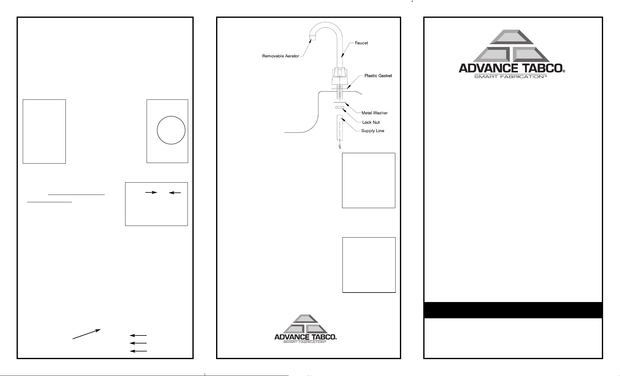
STEP 2
• Position sink (upside down) onto counter top surface at
desired location. Trace outer edge of Self-Rim with pencil.
(NOTE: Ensure sink is parallel to counter edges. Procedure
does not apply to DI-1-30, DI-1-5SP or DI-1-10SP.
Refer to chart for Cut Out dimensions.)
<< CORRECT MARKING
PROCEDURE
Pencil MUST be held
straight as possible.
INCORRECT >>
MARKING
PROCEDURE
• Remove sink and draw a second line 3/8” parallel to the
inside of the marked line - that will be the CUT line
(As shown).
• NOTE: BEFORE CUTTING
COUNTER TOP, REFER TO THE
CHART TO VERIFY CUTOUT
DIMENSIONS!
REMEMBER:
MEASURE TWICE, CUT ONCE!
• Drill 1/4” hole 1 to the inside of cut line then use 1/2” drill
bit to enlarge hole.
• Apply masking tape along outer (sink edge) line. This will
prevent damaging countertop while cutting.
• Position jig saw blade into 1/2” hole and follow CUT LINE.
3/8
STEP 3
• Install Drain Apply a bead of
Plumber’s Putty
as shown.
asher
1/4” continuous bead of
Plumber’s Putty.
Rubber W
Fiber Washer
Die Cast Nut
STEP 4
• Install Faucet (as shown).
STEP 5
• Remove masking tape from counter
surface and position sink into opening to
ensure proper fit.
STEP 6
• Remove sink from opening and apply
1/4” bead sealant along edge of cut out.
• Install sink into counter top.
• Insert slotted end of screw thru clearance hole in clip and
secure by turning Counter-Clockwise.
• Slide clip into end of Roll Form track (As
Shown) and position where desired and
hand tighten. Once all clips are in position, tighten with screwdriver -
DO NOT OVERTIGHTEN!
• Wipe excess Silicone from counter
surface.
STEP 7
• Connect Drain and Faucet supply lines.
EDGEWOOD, NY 11717-8380
© ADV
ABCO, June 2005
ANCE T
INSTALLATION INSTRUCTIONS for
DROP-IN SINKS
CHECK FOR CONCEALED DAMAGE
FILE CLAIM WITH FREIGHT CARRIER
op-ins manufactured by
Dr
constructed for countertop installations. Only one compartment
units intended for HAND SINK USE ar
approved. Suggested end use for drop-in sinks include dump
sinks, bar sinks, wash sinks and hand sinks.
ANCE TABCOare designed and
ADV
e NSF listed and
This Carton Contains:
1 ea. Sink Bowl
Basket Type Drain (sub assembly)
(see chart).
Faucet (sub assembly) (see chart).
Mounting Clips (see chart).
TOOLS REQUIRED:
• Drill Motor
• 1/4” - 1/2” Drill Bits
• Long Shank Screw Driver
• Ruler or Tape Measure
• Pencil
• Adjustable Wrenches (2)
• Pipe Wrench
• Saber Saw or Jig Saw
MATERIAL REQUIRED:
• Silicone Sealant
• Plumbers Putty
• Masking Tape
RECOMMENDED SAFETY MATERIALS:
• Safety Glasses
• Work Gloves
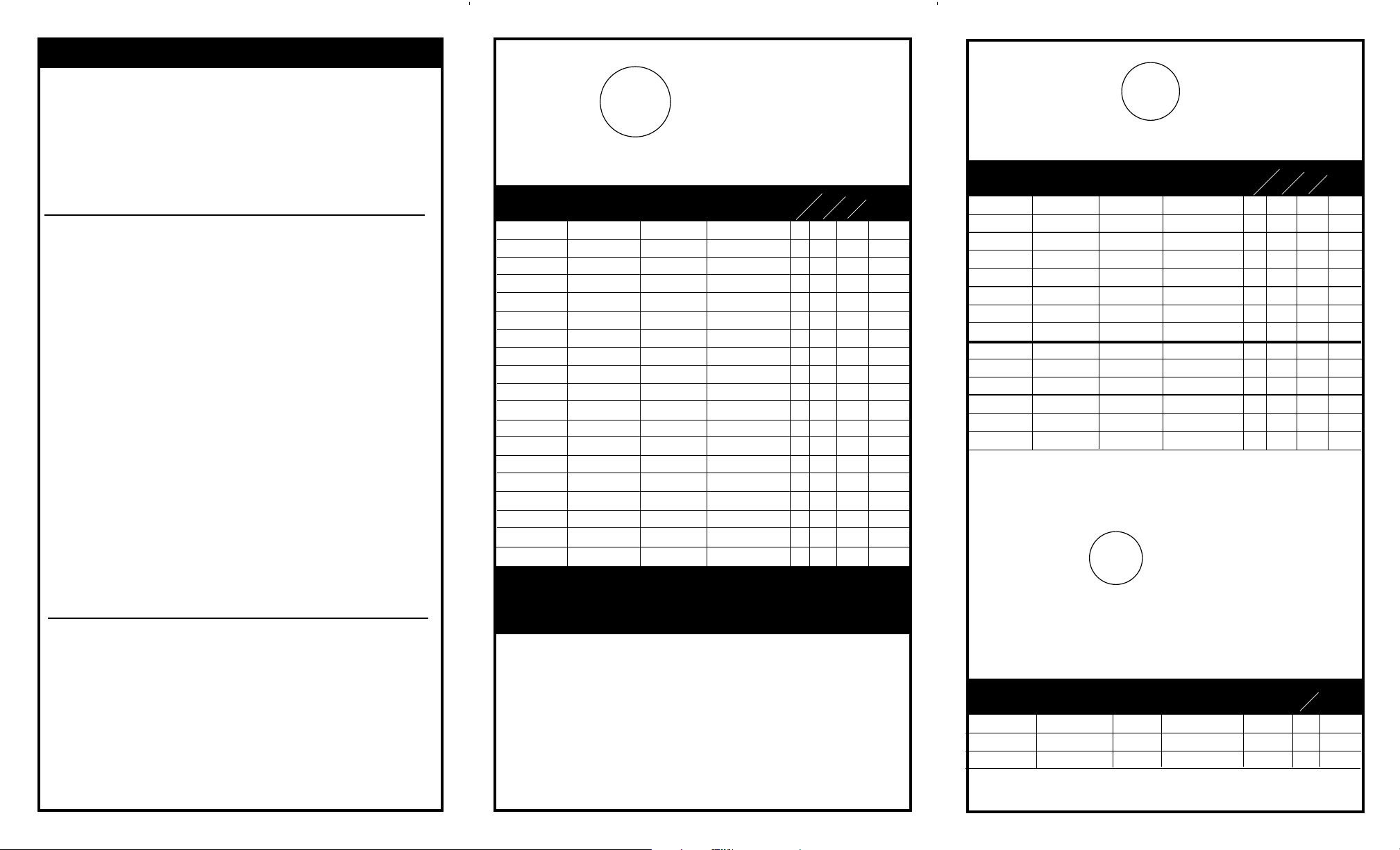
U Channel
MODEL #
DI-1-5
DI-1-5SP
††
DI-1-9
DI-1-10
DI-1-10SP
DI-1-25
DI-1-30
DI-1-35
DI-1-168
DI-1-208
*
DI-1-2012
*
DI-1-2812
**
DI-2-10
*
DI-2-1410
*
DI-2-2012
*
DI-2-208
*
DI-3-10
*
DI-3-1410
*
DI-3-1612
*
Installation
LENGTH IS LEFT TO RIGHT
Bowl Dim. Overall Dim. Cutout Size Ship
L x W x D L x W 1 1/4” Radius Weight
10 x 14 x 5
10 x 14 x 5
9 x 9 x 3
10 x 14 x 10
10 x 14 x 10
9 x 9 x 5
14 x 10 x 5
14 x 10 x 5
16 x 14 x 8
20 x 16 x 8
20 x 16 x 12
28 x 20 x 12
10 x 14 x 10
14 x 16 x 10
20 x 16 x 12
20 x 16 x 8
10 x 14 x 10
16 x 14 x 10
16 x 20 x 12
SUPPLIED WITH K-52 GOOSENECK FAUCET
†† SUPPLIED WITH WATER FILLER FAUCET & GRATING
**SUPPLIED WITH K-53 FAUCET WITH 12 SPOUT
13 x 19
13 x 19
12 x 14
13 x 19
13 x 19
12 x 14
16 x 15
17 x 15
19 x 19
23 x 21
23 x 21
31 x 25
25 1/2 x 19
33 1/2 x 21
45 1/2 x 21
45 1/2 x 21
38 x 19
50 x 21
56 x 25
*SUPPLIED WITH K-50 FAUCET
WIDTH IS FRONT
12 1/4 x 18 1/4
12 1/4 x 18 1/4
11 1/4 x 13 1/4
12 1/4 x 18 1/4
12 1/4 x 18 1/4
11 1/4 x 13 1/4
15 x 14 1/4
16 1/4 x 14 1/4
18 1/4 x 18 1/4
22 1/4 x 20 1/4
22 1/4 x 20 1/4
30 1/4 x 24 1/4
24 3/4 x 18 1/4
32 3/4 x 20 1/4
44 3/4 x 20 1/4
44 3/4 x 20 1/4
37 1/4 x 18 1/4
49 1/4 x 20 1/4
55 1/4 x 24 1/4
# Faucets
1 1 8 9 lbs.
1 1 4 13 lbs.
1 1 8 8 lbs.
1 1 8 11 lbs.
1 1 4 18 lbs.
1 1 8 8 lbs.
1 1 4 11 lbs.
1 1 8 8 lbs.
1 1 12 15 lbs.
1 1 12 29 lbs.
1 1 12 25 lbs.
1 1 12 42 lbs.
1 2 12 20 lbs.
1 2 12 33 lbs.
1 2 16 40 lbs.
1 2 16 29 lbs.
2 3 16 32 lbs.
2 3 16 52 lbs.
2 3 16 60 lbs.
TO BACK
# Clips
# Drains
U Channel
Installation
SMART SERIES
LENGTH IS LEFT
MODEL #
SS-1-1715-7
SS-1-1715-10
SS-1-1919-7
SS-1-1919-10
SS-1-1919-12
SS-1-2321-7
SS-1-2321-10
SS-1-2321-12
SS-2-3321-7
SS-2-3321-10
SS-2-3321-12
SS-2-4521-7
SS-2-4521-10
SS-2-4521-12
Bowl Dim. Overall Dim. Cutout Size Ship
L x W x D L x W
14 x 10 x 7 1/2
14 x 10 x 10
16 x 14 x 7 1/2
16 x 14 x 10
16 x 14 x 12
20 x 16 x 7 1/2
20 x 16 x 10
20 x 16 x 12
14 x 16 x 7 1/2
14 x 16 x 10
14 x 16 x 12
20 x 16 x 7 1/2
20 x 16 x 10
20 x 16 x 12
U Channel
Installation
™
17 x 15
17 x 15
19 x 19
19 x 19
19 x 19
23 x 21
23 x 21
23 x 21
33 1/2 x 21
33 1/2 x 21
33 1/2 x 21
45 1/2 x 21
45 1/2 x 21
45 1/2 x 21
TO RIGHT
aucets
Faucet &
Bubbler
Optional
TO BACK
# Drains
# Clips
WIDTH IS FRONT
1 1/4” Radius Wt.
16 1/4 x 14 1/4
16 1/4 x 14 1/4
18 1/4 x 18 1/4
18 1/4 x 18 1/4
18 1/4 x 18 1/4
22 1/4 x 20 1/4
22 1/4 x 20 1/4
22 1/4 x 20 1/4
32 3/4 x 20 1/4
32 3/4 x 20 1/4
32 3/4 x 20 1/4
44 3/4 x 20 1/4
44 3/4 x 20 1/4
44 3/4 x 20 1/4
# F
11 8 12
11 8 14
1 1 12 16
1 1 12 18
1 1 12 20
1 1 12 20
1 1 12 22
1 1 12 25
1 2 12 33
1 2 12 35
1 2 12 37
1 2 12 38
1 2 12 39
1 2 12 40
NOTE:
The corners of ALL Cutouts are to
have a
1-1/4” Radius.
SMART SERIES™For the Classroom
WIDTH IS FRONT TO BACK
MODEL #
SCH-2317
SCH-1-2517L
SCH-1-2517R
LENGTH IS LEFT TO RIGHT
Bowl Dim. O.A. Dim. Cutout Size Ship
L x W L x W
16 x 14 x 7 1/2
16 x 14 x 7 1/2
16 x 14 x 7 1/2
23 x 17
25 x 17
25 x 17
1 1/4” Radius Weight
22 1/4 x 16 1/4
24 1/4 x 16 1/4
24 1/4 x 16 1/4
Faucet Holes
Left Right
11 8 16
3 1 12 18
1 3 12 18
# Clips
 Loading...