

Page 1

THIS PRODUCT IS DESIGNED FOR PROFESIONAL INSTALLATION ONLY
RF-215
PROFESSIONAL VEHICLE SECURITY SYSTEM
INSTALLATION MANUAL
(For Authorized Dealers Only)
WIRING DIAGRAM
Page 2
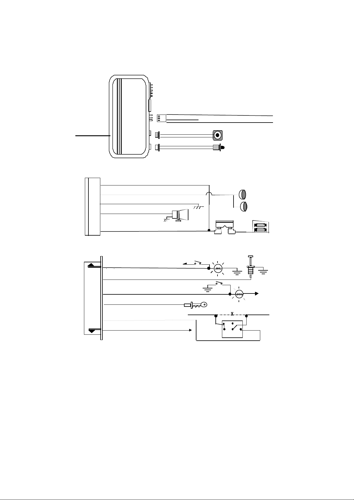
: 6 Pin White Mini Connector
Wire
H3/3 Green Wire: (
-
) 200mA Lock Pulse, (+) 200mA Unlock Pulse
H3/1 Blue Wire: (
-
) 200mA Unlock P
ulse, (+) 200mA Lock Pulse
H4 H5
5. Red Wire: +12V To Constant Battery Source
2. Blue Wire: Instant Trigger Ground
4. Yellow Wire: To Ignition Switched + 12V
85
86
30
87a
87
To start solenoid
From ignition switch
Red
Orange wire
H1
: Main 5 Pin White harness
H2
H3
H7: Black Antenna
H1: MAIN 5 PIN WIRE HARNESS :
H2: 6 PIN MINI CONNECTO R WIRE HARNESS:
1. Red / White Wire: Parking Light Relay input
2. White Wire: Parking Light Relay Output
3. Black Wire: Ground to Vehicle FRAME
4. Brown Wire: Positive output To
Siren Or Horn (Programmable)
1. Violet Wire: Positive Door Pin Switch
12V
H3/2 Red Wire:12V output (+)
2 Pin Blue Plug For
Valet Switch
2 Pin White Plug For
LED Indicator
15A Fuse
3. Green Wire: Negative Door Pin Switch Input
5. Orange Wire: 200mA Grounded when armed
6. Gray Wire: (-) 200mA Programmable Output
Channel 2 / 2 Step Door Unlock / Pager Output.
12V
Cut
Page 3
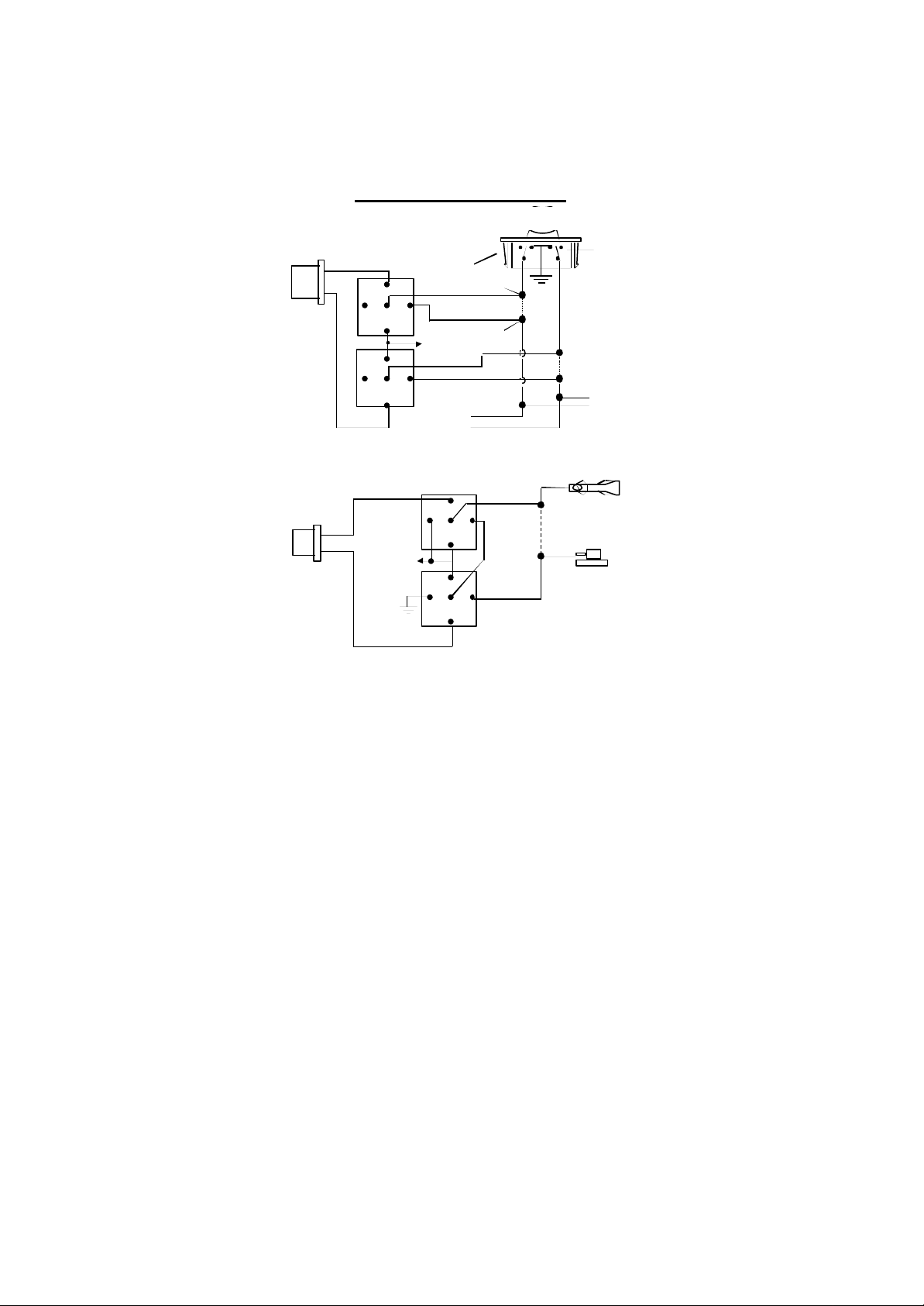
DOOR LOCK DIAGRAMS
+12V
3 Pin Plug
Compressor
5-WIRE ALTERNATING DOOR LOCK
To Alarm
Green Wire
87
87
Blue Wire
86
87a
85
86
87a
85
Master Door
Lock Switch
30
+12V
30
To Slave Door
Lock switches
Cut the Existing
Unlock Wire
Splice
Splice
Cut the Existing
X
Lock Wire
To Door
Lock
Motor
VACUUM OPERATED CENTRAL LOCKING
Green Wire
3 Pin
Plug To
Alarm
+12V
Blue Wire
VACUUM OPERATED DOOR LOCKING SYSTEM:
86
30
87a
87
85
86
87a
87
30
85
X
Door Switch
Cut
TYPICAL OF MERCEDES BENZ AND AUDI.
Locate the wire under the driver's kick panel. Use the
voltmeter connecting to ground, verify that you have the
correct wire with the doors unlocked, the voltmeter will
receive "12 volts". Lock the doors and the voltmeter will
read "0 volt". Move the alligator clip to +12V and the
voltmeter will receive "12 volts". Cut this wire and make
connections. Be sure to program door lock timer to
3 seconds.(See Feature II – 1 Programming.)
Page 4
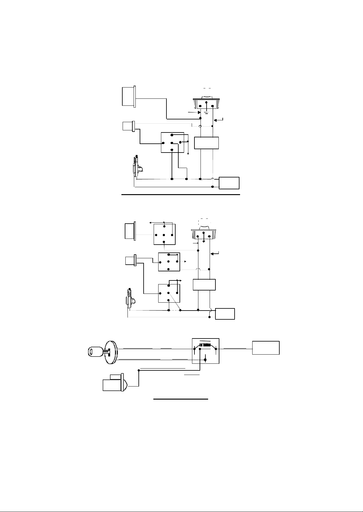
2 STEP DOOR UNLOCK WIRE CONNECTION FOR
X
To All Other
OEM Door
Lock Relay
X
Existing Pos.
Lock Wire
Existing Pos.
Unlock Wire
OEM Door
87
Wire
87
30
85
GROUND SWITCHED DOOR LOCKS
6-Pin
Plug
From
Alarm
3 Pin Plug
To Alarm
H2/6 Gray Wire
H7/3 Green
Wire
Door Lock
OEM Door Master Lock Switch
Unlock
Existing Neg.
Unlock Wire
Lock
Existing Neg.
Lock Wire
H7/1 Blue
Wire
Door Unlock
OEM
Door Lock
Motor
87
85
86
87A
30
+ 12V
Cut Existing Unlock
Door Lock
Motors
2 STEP DOOR UNLOCK WIRE CONNECTION FOR
POSITIVE SWITCHED DOOR LOCKS
+12V
6-Pin
H2/6
Plug
Gray Wire
From
Alarm
H7/3 Green
Door Lock
H7/1 Blue
Wire
Door Unlock
OEM Driver's
Door Lock
Motor
86
87
87A
30
86
30
86
30
Cut Existing Unlock
STARTER DISABLE
<12V (+) Ignition> <Red>
<Starter Wire (key side)>
<Starter Wire (motor side)>
OEM Door Master Lock Switch
Unlock
85
87A
85
+ 12V
87A
85
<Yellow>
<Purple>
+ 12V
+ 12V
Lock Relay
RK-1
87a
87
Lock
To All Other
Door Lock
Motors
<White Wire>
86
Orange
Starter Disable
Wire
STARTER
PROGRAMMING
PROGRAMMING TRANSMITTER:
Enter:
1. Turn the Ignition 'switch ‘OFF/ON’ 3 TIMES and stay in ON position. Within 15
seconds,
Page 5

2. Push the Valet switch 3 times and hold in on the 3rd push; when a long chirp is
heard then release the valet switch. You are now in the Transmitter programming
mode.
Program:
1. Press any button on the first transmitter until the siren responds with a confirming
chirp; the first transmitter is now programmed.
2. Press any button on the second transmitter until the siren responds with a
confirming chirp; the second transmitter is now programmed.
3. Apply the same procedure to program any 3rd and 4th transmitters.
Exit: Turn Ignition to 'OFF' position, or leave it for 15 seconds. 3 long chirps will
confirm exit.
Note: If more than 4 transmitters programmed, the system will only keep the last 4
transmitters.
ALARM FEATURE “I” PRORAMMING:
1. Turn the Ignition 'switch ‘ON/OFF’ 3 TIMES and stay in OFF position.
2. Push the Valet switch 2 times and hold in on the 2nd push; when a long chirp is heard
then release the valet switch. You are now in the Alarm feature ‘I’ programming
mode.
3. Press the transmitter button corresponding to the feature you want to program.
a. The factory default settings is always [1] LED flash, [1] chirp.
4. Depress the transmitter button again to change the feature. Simply keep pressing
the transmitter button again until the module advances to your desired setting.
Press
Transmitter
Button
1
2
3
Exit: Turn Ignition to 'ON' position, or leave it for 15 seconds. 3 long chirps will confi rm exit.
One Chirp /
LED one pulse
Factory Default Setting
Chirps on Chirps off
Automatic Rearm On Automatic Rearm Off
With Door Ajar error chirp Bypass Door Ajar error chirp.
Two Chirps /
LED two pulse
ALARM FEATURE “II” PRORAMMING:
1 Turn the Ignition 'switch ‘ON/OFF’ 3 TIMES and stay in OFF position.
2 Push the Valet switch 4 times and hold in on the 4th push; when a long chirp is
heard, then release the valet switch. You are now in the Alarm feature ‘II’
programming mode.
3 Press the transmitter button corresponding to the feature you want to program.
Press
Transmitter
Button
One Chirp /
LED one pulse
Factory Default
Two Chirps /
LED two pulse
Three Chirps /
LED three pulse
Setting
1
0.9-second Door lock
pulses.
3.0-second Door lock
pulse.
Double pulse unlock
Page 6

2
Active arming Passive arming
without passive door
Passive arming with
passive door locking.
locking
3
Ignition controlled
door locks & unlocks
Without ignition
controlled door locks
& unlocks
Exit: Turn Ignition to 'ON' position, or leave it for 15 seconds. 3 long chirps will confirm exit.
ALARM FEATURE “III” PRORAMMING:
1 Turn the Ignition 'switch ‘ON/OFF’ 3 TIMES and stay in OFF position.
2 Push the Valet switch 6 times and hold in on the 6th push; when a long chirp is
heard, then release the valet switch. You are now in the Alarm feature ‘III’
programming mode.
3 Press the transmitter button corresponding to the feature you want to program.
Press
Transmitter
Button
1
2
3
Exit: Turn Ignition to 'ON' position, or leave it for 15 seconds. 3 long chirps will confirm exit
One Chirp /
LED one pulse
Factory Default
Setting
H1/4 Brown Wire =
Siren Output
H2/6 Gray Wire = Trunk
(Channel 2) Output
Car Jacking Off Car Jacking On
Two Chirps /
LED two pulse
H1/4 Brown Wire =
Horn Output
H2/6 Gray Wire = Two
Step Door Unlock
Output
Three Chirps /
LED three pulse
H2/6 Gray Wire = Pager
Output
ALARM FEATURE “IV” PROGRAMMING:
1. Turn the Ignition 'switch ‘ON/OFF’ 3 TIMES and stay in OFF position.
2. Push the Valet switch 8 times and hold on the 8th push until FOUR chirps with a long
chirp is heard then release the valet switch. You are now in the Alarm feature ‘I V’
programming mode.
3. Press and hold the transmitter button for two seconds to enter shock sensor
program mode.
Press
Transmitter
Button
1
ADJUST AND TEST THE SENSITIVITY LEVEL OF THE SHOCK SENSOR
1. Turn the Ignition 'switch ‘ON/OFF’ 3 TIMES and stay in OFF position.
2. Push the Valet switch 8 times and holding in on the 8th push until four chirps with a
long chirp is heard then release the valet switch. You are now in the Alarm feature
‘Shock Sensor’ programming mode.
One Chirp /
LED one pulse
Factory Default Setting
Two Chirps /
LED two pulse
Shock Sensor Program Mode
Page 7

3. Press and hold button for 2 seconds. One long siren chirp to indicates the unit is
ready to accept adjustments of the shock sensor.
4. Press button on the transmitter once. This will decrease sensitivity level by one,
each time the button is pushed, a decrease is made the siren/horn chirp will respond
with [1] chirp, while 2 chirp indicates the minimum of sensitivity.
5. Press button on the transmitter once. This will increase sensitivity level by one,
each time an increase is made the siren/horn chirp will respond with [1] chirp, while
2 chirp indicates the maximum sensitivity.
6. Hit the bumper or strong metal part of the vehicle to test the threshold level of the
sensor.
a). Activate the warn -away (first stage the shock sensor), the siren will emit a short
chirp.
b). Activate the full alarm (second stage the shock sensor), the siren will emit a long
chirp.
7. When you are satisfied with the setting, press button to lock in the adjustment.
One long siren chirp will indicate the unit has locked in the adjustment.
Note: If 20 seconds of inactivity expires, or you turn on the ignition during of above
steps, the unit will exit the program mode and return to the disarmed mode. Three
long chirps to confirm exit.
This device complies with part 15 of the FCC rules. Operation is subject to the
following two conditions.
1) This device may not cause harmful interference, and
2) This device must accept any interference received, including interference that may
cause undesired operation.
Per FCC 15.21, you are cautioned that changes or modifications not expressly
approved by the part respons ible for compliance could void the user’s authority to
operate the equipment.
Page 8

THIS PRODUCT IS DESIGNED FOR PROFESIONAL INSTALLATION ONLY
RF-215
PROFESSIONAL VEHICLE SECURITY SYSTEM
OPERATION MANUAL
TRANSMITTER OPERATION
Transmitter Button System Function Remark
Button
– Button
Arm / Lock door
Arm and Delete Optional
Sensor
Press twice.
Page 9

Button
Button for 3 seconds
Button
– Button
Button
Button for 2 seconds
+ Button
+ Button for 1
seconds
II
Car Locator System in Armed.
Panic function Press 3 seconds
Disarm & Unlock Door
Two Steps Door Unlock &
Disarm System
Car Locator
Pop Tr unk Release Press 2 seconds
Silent Arm / Disarm Ignition in "off" position.
Activate Car-Jacking Ignition in "on" position.
Switching code For 2nd
Car Operation.
Press twice within 3
seconds.
ACTIVE ARMING – LOCK & ARM:
1. Press button on transmitter.
2. The siren will chirp once and the parking lights will flash once indicating that the
system is now armed. The vehicle doors will lock upon arming when interfaced
with the security system.
Note: Defective sensor reminder: If the siren sounds 3 chirps, then you have left a
door, trunk, or hood lid ajar.
SILENT ARMING / DISARMING: Press the + button together on the
transmitter to arm or disarm your security system, No chirp sound will be heard; arm
/ disarm confirmation will be through the vehicles parking lights only.
SHOCK SENSOR / OPTIONAL SENSOR BY-PASS: Press the button on the
transmitter twice within 3 seconds will arm the security system, by-pass the shock
sensor or the optional sensor connected to 4 pin plug. The system will chirp one
additional time to confirm the sensor bypass mode was activated. The sensor
bypass feature is programmed to activate for one arming cycle only. The security
system will return to normal operation during the next arming cycle
PASSIVE ARMING:
Active arming / disarming is controlling your security system via the remote
transmitter. This security system is equipped with an optional Passive Arming
feature, which allows the security system to arm 30 seconds after the last door is
closed. Operation is as follows.
1. Turn the ignition to the “OFF” position and exit the vehicle.
2. After all entrances are closed, the security system LED will flash fast for 30
seconds. If you reopen any door / hood / trunk, the security system LED will stop
flashing. It will begin flashing again once all vehicle entrances are closed.
3. After 30- second timer has elapsed, the security system will automatically “ARM”.
The siren will chirp [1] time and the parking lights will flash [1] time.
PASSIVE DOOR LOCKING:
The vehicle doors will automatically lock after passive arming cycle has been
completed.
ACTIVE DISARMING – UNLOCK & DISARM:
Page 10

1. Press the button on the transmitter.
2. The siren will chirp twice and parking lights will flash twice to indicate that the
security system is now disarmed. The vehicle doors will unlock and disarm when
interfaced with the security system.
TAMPER DISARMING: If the alarm is triggered; upon disarming the system, the
siren will chirp 4 times and parking lights will flash 3 times.
TWO STEP DOOR UNLOCK: This feature will independently unlock the driver’s
door only when disarming the security system. Pushing the button on the
transmitter a second time within 3 seconds will unlock the entire vehicle.
AUTOMATIC RE-ARM: If this feature is selected, the security system will
automatically re-arm itself 60 seconds after disarming with remote transmitter.
Automatic rearm will cancel if any door is opened before the 60 seconds timer has
elapsed.
DISARMING WITHOUT A TRANSMITTER
The Override function may be used if the remote transmitter is lost or inoperative.
1. Enter the vehicle and turn the ignition switch to 'ON’ position. (Alarm will sound.)
2. Within 10 seconds push and release the valet switch
The alarm will stop sounding and enter the disarm mode. You can now start and
operate the vehicle normally.
VALET MODE:
The valet switch allows you to temporarily bypass all alarm function, eliminating the
need to hand your transmitter to parking attendants or garage mechanics. When
the system is in valet mode, all alarm functions are bypassed, however, the remote
panic feature and remote door locks will remain operational.
Enter Valet Mode:
1. Turn the ignition to “ON” position.
2. Push and hold valet switch for 2 seconds or until the LED turns on. The LED will
remain on as long as the system is in 'valet mode'.
Exit Valet Mode:
1. Return to normal operation, turn ignition 'ON'.
2. Push and hold valet switch for 2 seconds; the LED will turn off indicating the
system is exiting the valet mode.
PANIC FUNCTION:
The transmitter can be used as a remote panic switch to manually trigger the alarm
in case of emergency.
1. Press and hold the button on the transmitter for 3 seconds. The alarm will
immediately sound.
2. To stop the alarm, press and hold the or button for 3 seconds on the
transmitter, the panic mode will be turned off immediately.
3. If the button is not pressed, the alarm will automatically stop after 30 seconds.
Note: If the H3/6 Gray Wire is not a Tru nk release Output, (See Alarm Feature III-2
Programming), Press and hold the button on the transmitter for 3 seconds.
The alarm will immediately sound.
TRIGGER THE SYSTEM
When armed, your vehicle is protected as follows:
1. Light impacts will trigger the warn -away signal. A long chirp from siren/horn.
2. Heavy impacts / Doors open / Hood open / Trunk open / Turning on the ignition
switch- All will trigger the programmed sequence.
The starter disable relay (if installed) prevents the vehicle’s starter from cranking. The
siren and parking lights will turn on to alert of an intrusion for 30 seconds. Then the
Page 11

siren will stop and automatically reset and re -arm. If any the sensors or detectors are
still active, the alarm system will sound a maximum of six- 30 second cycles.
ANTI CAR-JACKING
Warning: If you don't need the car jacking function in this alarm system, be sure to
set car jacking feature “OFF”. This system is default setting Car-jacking “OFF”. (See
Alarm Feature III - 3 Programming. )
1. TRANSMITTER ACTIVATE THE CAR JACKING:
Press and hold + button on the transmitter for 1 second while the vehicle’s
ignition is ON. The parking light wills turns on for 1.5” seconds to indicate car
jacking activated.
2. DOOR SWITCH ACTIVATE CAR JACKING:
1. Turn the ignition switch to “ON” position, the system is armed.
2. Once the system is armed, if you are forced from the vehicle, the system will
active the car jacking trigger when the door is opened and closed while the ignition
is “ON”.
TRIGGER THE CAR JACK MODE:
3- timer circuits will function as follows:
First timer:
a. 50 seconds after the system has been triggered. The siren will start chirping for
15 seconds.
b. During this 15 seconds period of chirping, you will be alerting to push the valet
switch once to turn off the car -jacking feature.
c. If not, it will enter second timer car jacking.
Second timer:
65 seconds after the system has beer triggered. The siren starts alarming and the
parking light starts flashing.
Third timer:
90 seconds after the system has been triggered
a. The siren still alarming and the parking light flashing, and
b. The starter disable will activate to prevent the vehicle from starting.
c. It will remain active until the vehicle's battery power exhausted.
OVERRIDE THE SYSTEM TO TURN OFF CAR JACKING:
Turn the ignition switch from OFF to ON, and within 10 seconds push valet switch,
the siren will stop and the system disarmed
IGNITION CONTROL DOOR LOCKS.
If the vehicle’s door locks have been interfaced to the security system, the system will
automatically lock the vehicle's doors when the ignition is turned “ON” and /or unlock
the vehicle’s doors when the ignition is turned “OFF”.
TRUNK RELEASE.
Press and hold button on transmitter for two seconds to remote control the trunk
release or other electric devices.
CAR LOCATOR
Press the button on the transmitter to active car locator function. The siren will
chirp 6 times. The parking light will flash 12 times, allowing you to easily locate your
car.
ADJUST AND TEST THE SENSITIVITY LEVEL OF THE SHOCK SENSOR
1. Turn the Ignition 'switch ‘ON/OFF’ 3 TIMES and stay in OFF position.
Page 12

2. Push the Valet switch 8 times and holding in on the 8th push until four chirps with a
Off or Fast
3 flashes...
Trigger on door
long chirp is heard then release the valet switch. You are now in the Alarm feature
‘Shock Sensor’ programming mode.
3. Press and hold button for 2 seconds. One long siren chirp to indicates the unit is
ready to accept adjustments of the shock sensor.
4. Press button on the transmitter once. This will decrease sensitivity level by one,
each time the button is pushed, a decrease is made the siren/horn chirp will respond
with [1] chirp, while 2 chirp indicates the minimum of sensitivity.
5. Press button on the transmitter once. This will increase sensitivity level by one,
each time an increase is made the siren/horn chirp will respond with [1] chirp, while
2 chirp indicates the maximum sensitivity.
6. Hit the bumper or strong metal part of the vehicle to test the threshold level of the
sensor.
a). Activate the warn-away (first stage the shock sensor), the siren will
emit a short chirp.
b). Activate the full alarm (second stage the shock sensor), the siren will emit a long
chirp.
7. When you are satisfied with the setting, press button to lock in the adjustment.
One long siren chirp will indicate the unit has locked in the adjustment.
Note: If 20 seconds of inactivity expires, or you turn on the ignition during of above
steps, the unit will exit the program mode and return to the disarmed mode. Three
long chirps will confirm exit.
ALARM OPERATING CONDITION:
Function
1. Arm 1 Chirp 1 Flash Slow flash Locking On
2. Disarm 2or4
3. Trigger Alarming Flashing Slow flash On On
4. Panic Alarming Flashing Slow flash Locking On
Siren Parking
Lights
2 or 3
Chirps
Flashes
LED Doors Starter
Unlocking Off
flash
Disable
Pager
Option
ALARM INDICATORS
CHIRP INDICATORS: PARKING LIGHTS:
Chirp Function
Parking Light
1 chirp Arm 1 flash Arm
2 chirps
3 chirps
Disarm
Defective
2 flashes Disarm
3 flashes Disarm/
reminder
4 chirps
Disarm/
Intrusion
LED INDICATORS:
LED Function
LED Function
Off Disarmed 2 flashes...
pause
Slow flash Armed
Function
Intrusion
Trigger on trunk/hood
Page 13

pause switch
Fast flash Passive arming 4 flashes...
pause
On (solid) Valet mode 5 flashes...
pause
This device complies with part 15 of the FCC rules.
Operation is subject to the following two conditions.
(1) This device may not cause harmful interference, and
(2) This device must accept any interference received, including interference that may cause undesired
operation.
Per FCC 15.21, you are cautioned that changes or modifications not expressly approved by the part
responsible for compliance could void the user’s authority to operate the equipment.
Trigger on Dual Zone
Shock Sensor
Trigger on Ignition
switch
 Loading...