

Advance Security DELUXE 200 Installation guide

MAY/18/2005
DELUXE 200
REMOTE ENGINE STARTER
WITH KEYLESS ENTRY SYSTEM
INSTALLATION MANUAL
INTRODUCTION
INSTALLER WARNINGS
This Remote Starter with Alarm System is designed to be installed on fuel injected vehicles ONLY.
! For automatic transmission vehicle, this system must be installed and wired through a safety switch it will
not start in any forward or reverse gear.
! Some automatic transmission vehicle [mainly older GM vehicles with a purple starter wire] have a
mechanical-type park safety switch instead of electrical safety switch. The mechanical type does not
interrupt the starter circuit when the transmission is any gear and does not offer the 100% level of safety
required for remote starting purposes. Therefore, our system should never be installed on any vehicle that
uses a mechanical type park safety switch.
! For automatic transmission vehicle, once you install this system, you must verify that the vehicle will not
start any forward or reverse gear. Regardless of the type of vehicle.
! Read operation manual for operating and programming routine.
! Do not install any component near the brake, gas pedal or steering linkage.
! Some vehicles have a factory installed transponder immobilizer system that can severely complicate the
installation. There is possibility that this system can not be installed on some immobilizer equipped vehicles.
! Most vehicles have an SRS air bag system. Use extreme care and do not probe any wires of the SRS
system.
! Disconnect the car battery before connecting work on the vehicle.
! Check behind panels before drilling any holes. Ensure that no wiring harness or other components are
located behind the panels that would otherwise be damaged.
! Use conventional crimp lock, bullet on any wiring. Poor wiring, i.e. taped joints will possibly introduce
unreliability into the alarm system and may result in false alarms or incorrect operation.
! Install wiring neatly under carpets or behind trim to prevent possible damage to wires.
! For the wire operates the current more than 10A. We suggest soldering all connection point. Do not use
crimp lock type connectors or wire nuts.
INSTALLATION DIAGRAM
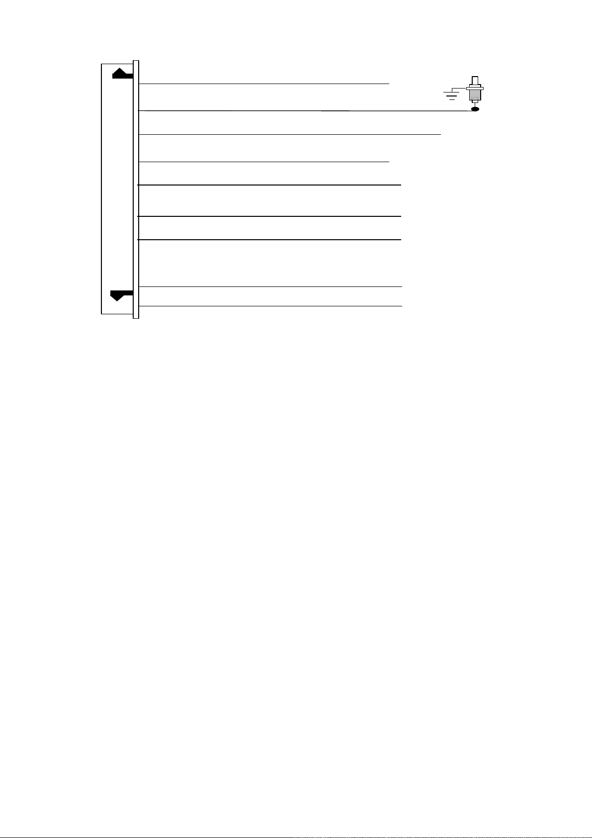
#H4. 9 PIN WIRE CONNECTION:
DELUXE 200-LCD
1
MAY/18/2005
IMPORTANT NOTE:
used.
Violet/White
Gray
Brown/Red
Thin Black
Red/White
Brown/Black
Factory Security Rearm Signal Output (Factory Default setting)
Or Ground Output During Start (Crank).
Black/White
LT Green/Black
Blue/Black
Wire: Tach. Signal Input
Wire: (
) Negative Safety Shut Down Input for Hood pin switch
-
Wire: (
Wire: (
Wire: (-) 200 mA Channel 3 (Trunk) Output
Or Factory Disarm Signal Output
Or Start Status (Shock Sensor Bypass Control) Output
Wire: (-) 200 mA Ignition 3 Control
Directly connect the Thin Black wire to the “GROUND” when this wire is not
) Positive Safety Shut Down Input for Brake switch.
+
) Neutral Safety Switch Input &
-
(
) Rem ote S tart Toggle Switch Input
-
Wire: (-) 200 mA Programmable output
Wire: (-) 200 mA Dome Light Control Output
Wire: (-) 200 mA Programmable output
Dual P ulse Door Unlock Output (Factory Default setting)
DELUXE 200-LCD
2
MAY/18/2005
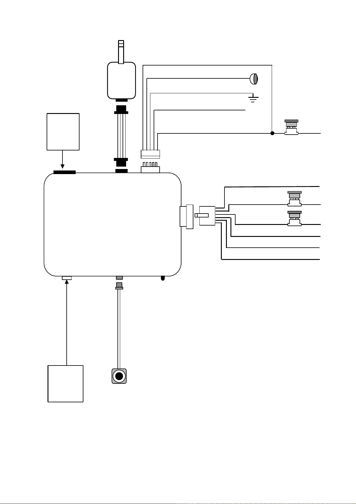
H4
9Pin Wire
Connection
H 4
9 Pin
White
Two Way
Transceiver
Antenna
H 3
4 Pin
Black
1. Red / White:
2. White:
3. Black:
4. Brown: (-)
5. Red:
H 2
5 Pin
White
H 1
6 Pin
White
Turn Indicator Relay Power input
Parking Light Relay Output
Ground to Vehicle Frame
200mA Horn Output
+12V Input
1. Violet:
2. Red:
3. Red:
4. Yellow:
10A Fuse
Starter Output
+12V Input
+12V Input
Ignition 1 output
20A
Fuse
20A
Fuse
H 5
6 Pin
White
H5
6 Pin White
Connector for
Door Lock &
Door unlock
Connection
H 6
2 Pin
Blue
Program
Switch
On Board
Program LED
Indicator
5. Pink:
6. Brown:
Ignition 2 Output
ACC/Heater Output
DELUXE 200-LCD
3
MAY/18/2005
V
WIRING
Keep wiring away from moving engine parts, exhaust pipes and high-tension cable. Tape wires that pass
through holes on the firewall to prevent fraying. Watches out sharp edges that may damage wires and causes
short circuit.
CAUTION: Do not connect the wire harness to the control module until all wiring to vehicle is complete.
6 PIN HEAVY GAUGE WIRING CONNECTIONS:
Remember that the system does to start a vehicle is duplicate the functions of the ignition key switch! Below,
we will explain the three basic functions of the ignition switch. Since this installation will require analysis of the
ignition switch functions, we recommend making the three connections below at the ignition switch harness
directly.
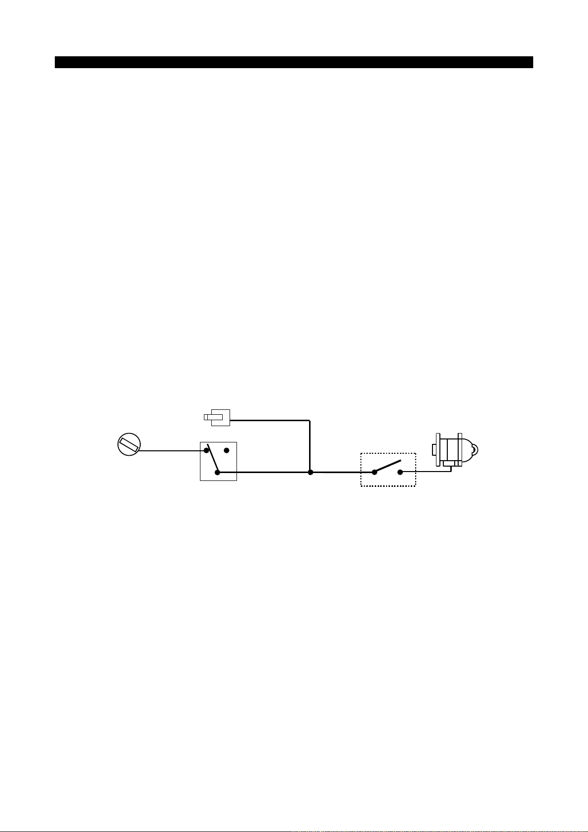
Violet wire – Starter Output –
Careful consideration for the connection of this wire must be made to prevent the vehicle from starting
while in gear. Understanding the difference between a mechanical and an electrical Neutral Start Switch
will allow you to properly identify the circuit and select the correct installation method. In addition you will
realize why the connection of the safety wire is required for all mechanical switch configurations.
Failure to make this connection properly can result in personal injury and property damage.
In all installations it is the responsibility of the installing technician to test the remote start unit and assure
that the vehicle can not start via RF control in any gear selection other than park or neutral.
In both mechanical and electrical neutral start switch configurations; the connection of the VIOLET wire will
be made to the low current start solenoid wire of the ignition switch harness. This wire has +12 volts when
the ignition switch is turned to the “START” (CRANK) position only. This wire have 0 volts in all other
ignition switch positions.
NOTE: This wire must be connected to the vehicle side of the starter cut relay (when used). For the
electrical neutral switch configuration, this connection must be made between the starter inhibit relay (when
used) and the neutral safety switch as shown in the following diagram.
Failure to connect this wire to the ignition switch side of the neutral safety switch can result in personal
injury and property damage. SEE NEUTRAL START SAFETY TEST FOR FURTHER DETAILS.
IOLET Wire
“Off”
“Acc”
Ignition
Switch
“On”
“Start”
Neutral Safety
Switch
Starter
Start Cut Relay
(When Used)
Closed in Park or
Neutral Only
Red wires – +12V Power Input –
Remove the two 20A fuses prior to connecting these wires and do not replace them until the satellite has
been plugged into the control module. These wires are the source of current for all the circuits the relay
satellite will energize. They must be connected to a high current source. Since the factory supplies (+) 12V
to the key switch that is used to operate the motor, it is recommended that these wires be connected there.
Note: If the factory supplies two separate (+) 12V feeds to the ignition switch, connect one RED wire of the
satellite to each feed at the switch.
Yellow wire – Ignition Output –
Connect the YELLOW wire to the ignition wire from the ignition switch. The ignition wire should receive "12
volts" when the ignition key is in the "ON" or “RUN” and "START" or “CRANK” position. When the ignition is
turned "OFF", the ignition wire should receive "0" voltage. The YELLOW wire must be connected.
Pink wire – Ignition 2 Output
Some vehicles have [2] ignition wires that must be power. Connect the PINK wire to the ignition 2 wire from
the ignition switch. The ignition wire should receive "12 volts" when the ignition key is in the "ON" or “RUN”
and "START" or “CRANK” position. W hen the ignition is turned "OFF", the ignition wire should receive "0"
voltage. If the PINK wire is not used, cap the end of the wire.
Brown wire – Accessory Output (Heater /ACC Output) –
Connect the BROWN wire to the accessory wire in the vehicle that powers the climate control system.
An accessory wire will show + 12 volts when the ignition switch is turned to the “ACCESSORY” or “ON” and
“RUN” positions, and will show 0 Volts when the key is turned to the “OFF” and “START” or “CRANK”
position. There will often be more than one accessory wire in the ignition harness. The correct accessory
DELUXE 200-LCD
4

MAY/18/2005
wire will power the vehicle’s climate control system. Some vehicle may have separate wires for the blower
motor and the air conditioning compressor. In such cases, it will be necessary to add a relay to power the
second accessory wire.
5 PIN WIRE HARNESS:
Red / White wire – Parking Light Relay Power Input –
The RED/WHITE wire is the input to the flashing parking light relay. The connection of the RED/WHITE
wire will determine the output polarity of the flashing parking light relay.
If the vehicle you are working on has +12volt switched parking light, you don’t need connect this wire. This
wire already connected to +12 volt.
If the vehicle’s parking light are ground switched, cut the RED/WHITE wire, connect the RED/WHITE wire
to chassis ground.
White wire – Parking Light Relay Output (10A power output) –
Connect the WHITE wire to the parking light wire coming from the headlight switch. Do not connect the
WHITE wire to the dashboard lighting dimmer switch. (Damage to the dimmer will result). The limitation of
the WHITE wire is 10 AMP max. Do not exceed this limit or damage to the alarm and parking relay will
result.
Black wire – System Ground –
This is main ground connection of the alarm module. Make this connection to a solid section of the vehicle
frame. Do not connect this wire to any existing ground wires supplied by the factory wire loom, make the
connection to the vehicle's frame directly.
Brown wire – (-) 200mA Horn Output –
This wire is provided to use the existing vehicle's horn as the keyless entry system's optional's warning
audible device. It's a transistorized low current output, and should only be connected to the low current
ground output from the vehicle's horn switch.
Red wire – System Power (+12V Constant) –
The RED wire supplies power to the system. Connect this wire to a constant +12 volt source.
BLACK 4-PIN CONNECTOR. – TWO-WAY TRANSCEIVER/ANTENNA MODULE
The Two-way transceiver/antenna mounts on the location above the belt line (dashboard) of the vehicle for
best reception. We suggest you mount it on the lower left or upper left-hand side of windshield.
Warning! Do not mount in such a manner that it obstructs the driver’s view.
- Remove the protective tape backing.
- Carefully align the two-way transceiver/antenna and apply to windshield.
- Route the black connector wire behind the trim and connect to the two-way transceiver/antenna.
- Connect the other end to the control module.
- Special considerations must be made for windshield glass as some newer vehicles utilize a metallic
shielded window glass that will inhibit or restrict RF reception. In these vehicles, route the two ways
transceiver/antenna module away from metallic shielded window glass as far as possible.
9 PIN WIRE CONNECTORS:
Violet / White wire – Tach. Input Connection –
Note: You should connect this wire if you program the Feature IV – 2 to “Engine Checking TACH.”
otherwise not to connect this wire and tap the end.
Note: No connection of this wire is required, if you use the voltage checking type mode.
This input provides the remote start system with information about the engine’s revolutions per minute
(RPM). It can be connected to the negative side of the coil in vehicle with conventional coils. In multi-coil
and high energy ignition system locating a proper signal may be more difficult. Once connected,
To test for a tachometer wire, a multi-meter capable of test AC voltage must be used. The tach wire will
show between 1V and 6V AC at idle, and will increase as engine RPM increases. In multi-coil ignition
system, the system can learn individual coil wire. Individual coil wires in a multi-coil ignition system will
register lower amounts of AC voltage. Also, if necessary, the system can use a fuel injector control wire for
engine speed sensing. Common locations for a tach. wire are the ignition coils itself, the back of the
gauges, engine computers, and automatic transmission computers.
IMPORTANT! Do not test tacho. wires with a test light or logic probe. The vehicle will be damaged.
How to find a tach. wire with your multi-meter
1. Set the ACV or AC voltage (12V or 20V is fine.)
2. Attach the (-) probe of the meter to chassis ground.
3. Start and run the vehicle.
4. Probe the wire you suspect of being the tach. wire with the red probe of the meter.
5. If this is the correct wire the meter will read between 1V and 6V.
DELUXE 200-LCD
5
MAY/18/2005
p
IMPORTANT NOTE: You must program the “Tach Signal” before trying to remote start.
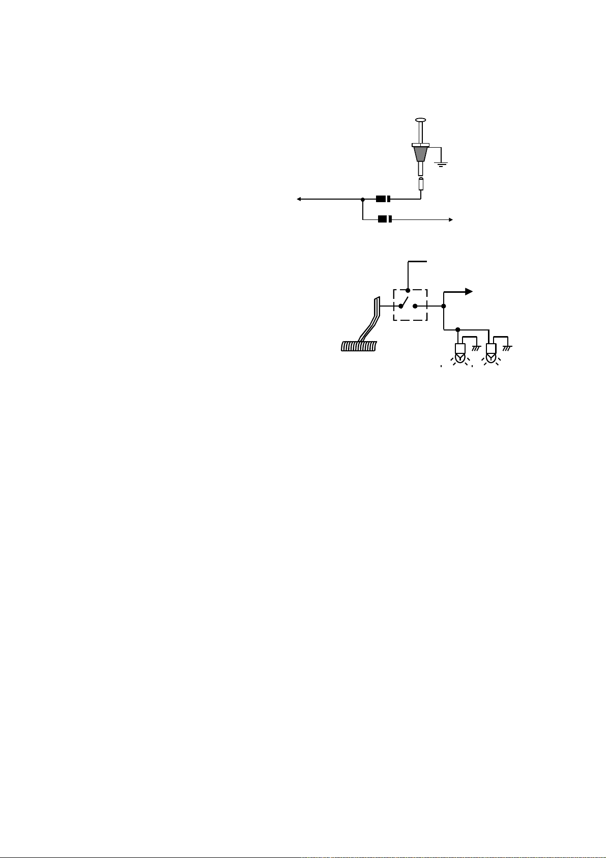
Grey wire – (-) Negative Safety Shut Down For Hood Pin Switch –
This wire provides an instant shutdown for the remote start, whenever it is grounded. Connect the wire to
the hood pin switch previously installed. This wire must be routed though a grommet in the firewall and
connected to the hood pin switch.
Important! This connection is a safety wire and
must be connected as shown and tested as
Hood Pin Switch
specifiled. Failure to do so may result in personal
injury or property damage. See detail of wiring in
the following diagram. This wire may also be
used if the vehicle brake light circuit switches
To: Grey Wire /
Negative safety
ground to the brake lights. An isolation diode
must be used for ground switched brake light
circuits and must be connected to the output of
Diode
To Vehicle Brake Switch
the brake switch.
Brown / Red wire – (+) Positive Safety Shut Down For Brake –
This wire provides an instant shutdown for the remote
start, whenever it gets +12volts. If the brake lights switch
in the vehicle switches +12 volts to the brake light circuit,
connect this wire to the output side of the brake switch.
This will allow the remote start to shut down if an attempt
is made to operate the vehicle without the key while
running under the control of the remote start. In most
Switch closes
When brake is
ress
de
+12 volts from fuse box
To Brown / Red
wire
Brake light bulbs
vehicles, in order to shift gear, the brake pedal must be
depressed. The brake input will in turn cause the remote
start unit to shut off. See below diagram.
Thin Black wire – (-) Neutral Safety Switch or (-) Remote Toggle Switch Input –
When the THIN BLACK wire is grounded, the remote start unit is operable. When this wire is open from
ground, the remote start is disabling.
1. The optional “remote start toggle switch” can be added on to temporarily disable the Remote Start
Device, it can prevent the vehicle from being remote started accidentally. This feature is useful if the
vehicle is being serviced or stored in an enclosed area. To disable the remote start, move the optional
remote start enable toggle switch to the OFF position. To enable the remote start, move the optional
remote start enable toggle switch to the ON position.
2. If needed, This wire can connect to the PARK/NEUTRAL switch in the vehicle. (See the TESTING
YOUR INSTALLATION GUIDE)
IMPORTANT NOTE: Directly connect the THIN BLACK wire to the “GROUND” when this wire is not
used.
Red / White wire – (-) 200ma Channel 3 (Trunk) Output –
This will become a 1 second pulse ground by activate channel 3 on transmitter for two seconds, the current
capacity of this wire is 200 mA. This feature allows you to remote control trunk release or other electric
device.
Brown / Black wire – (-) 200mA Factory Security Rearm Signal / Key Sensor Output –
Factory Security Rearm Signal Output
This output is programmable. If programmed rearm a factory installed security system. This wire will
supply a pulse whenever the remote start times out or is shut dowm using the transmitter and remote door
locking..
(Factory default setting.)
Ground Output During Start (Crank)
This wire will provide a 200mA ground output while the starter output of the remote start unit is active. This
output can be used to activate the Crank Low/Bulb Test wire found in some GM vehicles. This wire is also
referred to as the ECM wake up wire in some vehicles.
Black / White wire – (-) 200mA Dome Light Supervision Output –
This wire becomes grounded when the dome light controls circuit active. The current capacity of this wire is
200mA. This wire can control the operation of the interior lights. An optional 10 Amps relay can be used to
this system for interior lights operation. Upon disarming, the interior lights will remain on for 30 seconds.
LT. Green / Black wire – (-) 200ma Programmable Output –
Dual Pulse Door Unlock Output – (Factory default setting)
The dual pulse door unlock feature will work for the most fully electronic door lock circuit. The vehicle must
have an electronic door lock switch (not the lock knob or key switch), which locks and unlocks all of
vehicle's doors. When wired for this feature, press the disarm (or unlock) button one time will disarm the
alarm and unlock the driver's door only. If, press disarm (or unlock) button two times within 3 seconds, the
alarm will disarm and all doors will unlock.
DELUXE 200-LCD
6
 Loading...