

Page 1
MODEL 6978
REMOTE ENGINE STARTER
WITH ALARM SYSTEM MANUAL
This system works on only auto transmission vehicle.
A. 9 pin wire connection plug
B. 6 pin starter connection plug
Antenna Wire
C. 3 pin door lock plug
D. 4 pin optional sensor plug
2 pin LED plug
2 pin valet plug
E. 4 pin wire harness
WIRING:
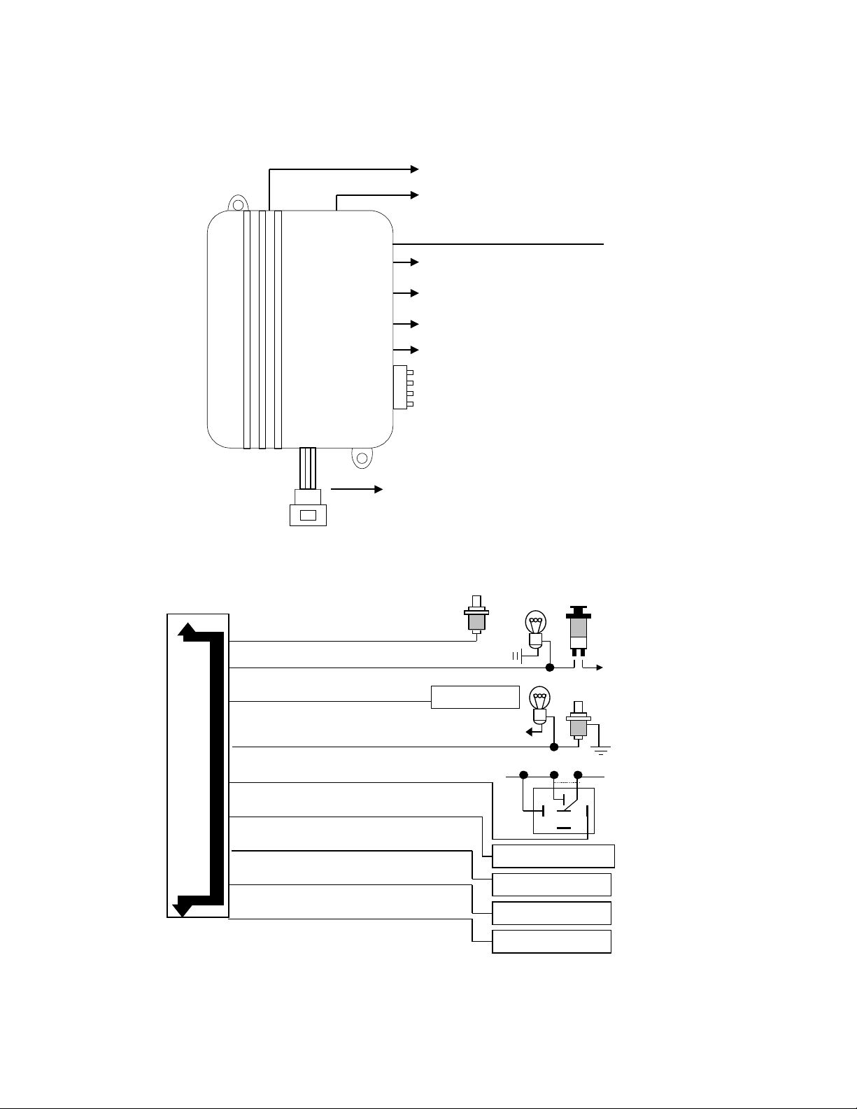
A. 9 pin wire connection plug:
F. 4 pin starter connector
Blue Wire: Instant Trigger Ground Input
Violet Wire: Positive Door Pin Switch
Yellow Wire: (-) 200mA C H 3 o utput
Green Wire Negative Door Pin Switch:
Orange Wire: 500m A Grounded when arm e d
Brown Wire: (-) 200mA of 2 steps d oor un lock.
Pink Wire: (-) 200mA of horn output
Gray Wire: (-) 200mA of ch ann el 2 output
White Wire: (-) 200mA of dome light output
CH 3 output
+12V
To start sole no id
To doo r unlock system
Horn/pager output
Channel 2 output
Cut
85 86
87a
87
+12V
From ignition switch
30
Dome light output
Page 2
B. 6 pin starter connection plug:
d
g
b
Gray: N egative safety input - hood or trunk
Violet: Negative safety input - hand brake
Yellow: Ignition 2 (-) output
Orange:
Blue: OEM alarm output
Green: Tachometer connection
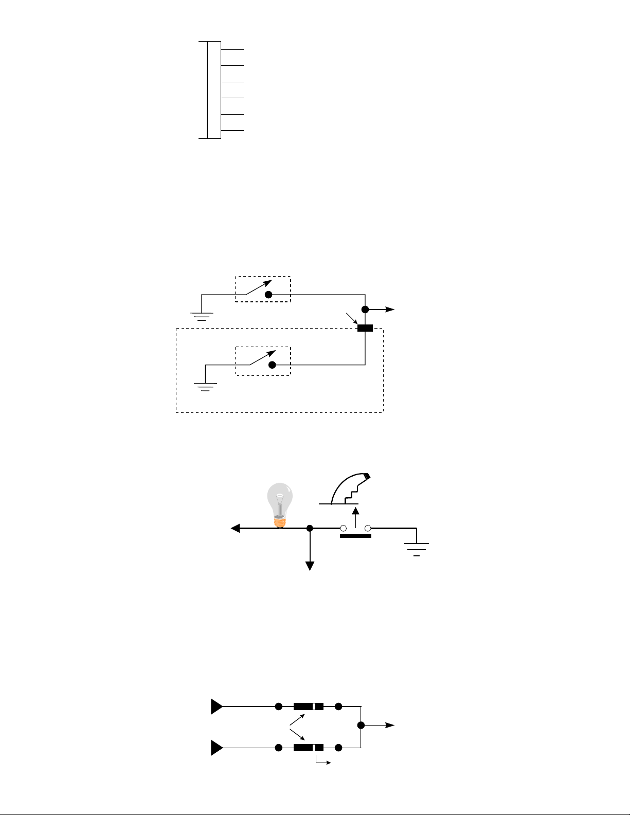
1. Gray wire – Negative safety input - hood or trunk.
Prevents engine from starting while vehicle is being serviced (or anytime that hood is raised).
a. Mount a hood tilt switch, as suggested by the manufacture, so as anytime the hood is raised the switch will be in the
closed position.
b. Wire the hood tilt switch as below figure. The alarm’s hood pin switch wire can be tied into this wire.
c. If desired an optional valet switch can be wired as below figure.
Note: The tilt switch used must be of a type that is environmentally sealed, so that corrosion will not prevent the
switch from making contact.
Pulsed gro und output during st art
Valet switch
Grommet throu
h
Gray wire
ulkhead panel
Hood tilt switch
Under Hoo
2. Violet wire:– Negative safety input - hand brake.
Shuts engine off if hand brake is released.
Connect to the vehicle’s hand brake light wire that shows +12Volts when the hand brake is pull up. See below:
Brake light switch
+ 12V
Hand brake light
Violet wire
Vehicle without a neutral safety switch
Some vehicles are not equipped with a true neutral safety switch. If the vehicles starter will engage when the gearshif t is
placed in any gear other than PARK or NEUTRAL, the following steps must be followed:
a. Using a voltmeter, find a wire on the back-up light/Neutral safety switch that show a positive voltage when the gearshift is
in any position other than PARK or NEUTRAL.
b. Connect that wire to the violet wire as shown below.
From brake switc h
Diodes
From neutral safety switch
White band
2
Violet wire
Page 3
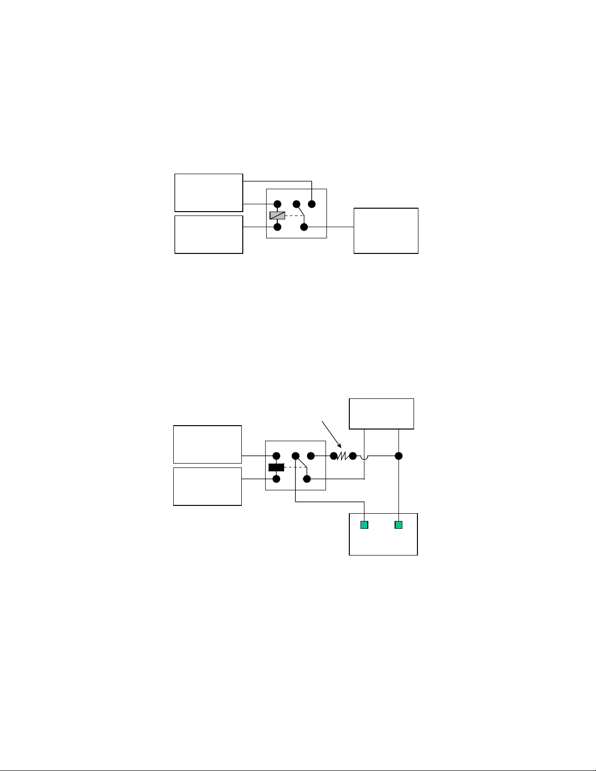
3.Yellow wire:- Ignition 2 ( - ) output --
This wire provides a 200mA (-) output in conjunction with the orange (+) 12V ignition output.
The yellow wire is designed to disarm a factor y installed security system. Some factor y systems must be disarmed to allow
remote starting. In m ost cases, the yellow wire may be connected directly to the factory alarm disarm wire. The correct wire
will show nagative ground when the key is used to unlock the doors or trunk . T his wire is us ually found in the k ick panel area
in the wiring harness coming into the car body from the door.
Additional Ignition circuits:
Some vehicles require that more than one ‘ignition’ wire be energized for the engine to run and/or the HVAC system to
operate. For those vehicles, wire an IGN 2 relay (not supplied) as shown below.
Do not connect any vehicle circuits together, they are isolated for a resaon.
(+) 12V
Constant fused
25A capable
Yellow (-)
Ignition 2 output
of system
86 87A
87
Accessory or
3085
ignition 2 wire
from ignition
key switch
GM VATS (or Pass-Key) starter lockout: These vehicles have a resistor embedded in their ignition key. If the VATS
decoder does not measure the c orrect resistanc e acros s two sensor s in the ignition k ey switch, the starter and the f uel pum p
are disabled for up to 5 min. T he system includes a ‘VATS pack’ of resistors which allow you to duplicate the value of the
keys’ resistor, using the diagram below.
The VATS sensor wires ar e available com ing out of the steeling colum n, typically on the left side. T he m id-eighties Corvettes
used a brown wire and a yellow wire (not the brown and yellow wires of the ignition switch harness ). In the late eighties, all
VATS equipped vehicles used a violet/white and white/black. These wires often change color in a two wire connector at the
base of the steeling column, c hanging into two white 20 gauge wires (often in orange tubing as they go up the colum n). O ne
VATS wire will show a constant ground, and the other is the measurement input.
Note: When making these connections, don’t worry about which VATS wire is which.
VATS Pass-key
decoder module
X
CUT
(+) 12V
Constant fused
Yellow (-) IGN
2 output
Proper value
resistor
86 87A
87
3085
X
Ignition switch
sensing terminals
4. Orange wire –Pulsed ground output during start --
This wire provides a 200mA (-) output while the starter output of the remote start unit is active. This output can be used to
activate the Crank Low/Bulb Test wire found in s ome GM vehic les. This wire is also r eferred to as the ECM wak e up wire in
some Chrysler vehicles.
Note: The output is low current output and must use with a relay if the circuit's requirement is more than 200mA.
5. Blue wire - OEM alarm output --
The blue wire can be use to connected to an available auxiliary output of an existing rem ote security system, that use to
disarm that alarm system.
6. Green wire-- Tachometer connection--
This is the module’s engine RPM signal. In cars with a separate coil. It can be found at the (-) terminal of the coil. In electronic
ignition system vehicle, locating the tachometer wire can be more involved. The tachometer wire, when tested with a
voltmeter set to AC voltage, will test between 1V and 6V at idle, and will increase as engine RPM increases. T he tachometer
wire is often accessible at the electronic distributor. Below are some common colors and location of vehicles.
3
Page 4
GM. : White, at coil or at HEI distributor. With some three-coil V6 motors, violet/white.
t
Ford: Tan/yellow or yellow/blue, at coil, at diagnostic connector, or at electronic distributor.
Toyota/Lexus: (-) G terminal of gray diagnostic connector under hood.
Honda/Acura: Blue, in two-pin connector forward of distributor.
Mercedes-Benz: Black, at coil under rubber boot.
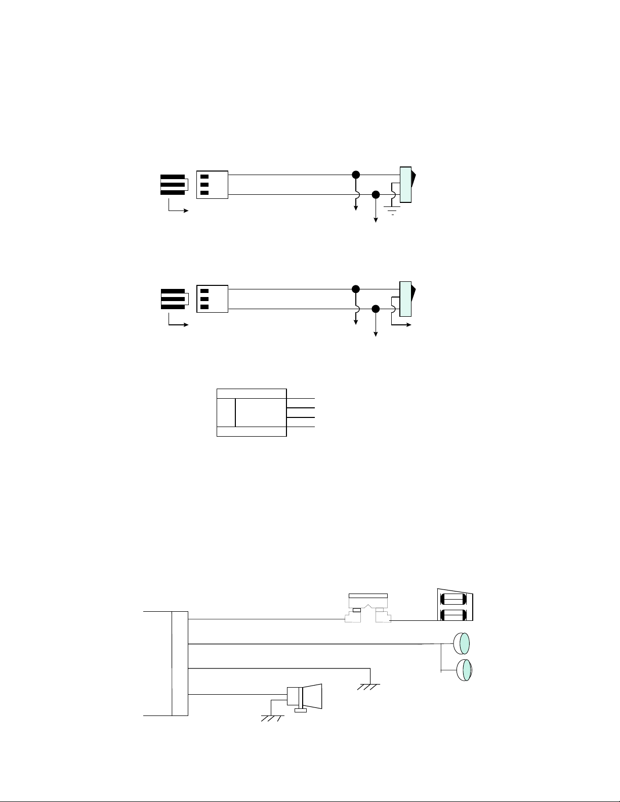
C. 3 pin door lock plug:
These wires will provide either a pulsed ground output to the fac tory door lock control relay, or a pulsed + 12 volts output to
the factory door lock control relay. The current capacity of these wire is 200 mA.
1). 2-Wire "Negative Trigger" Power Lock System.
Blue wire
Green wire
3 pin mini-molex connector
(-) Unlock pulse
(-) Lock pulse
To existing
Master
locking
switch
Door lock relay
2). 2-Wire "Positive Trigger" Power Lock System.
Blue wire
Green wire
3 pin mini-molex connector
(+) Lock pulse
(+) Unlock pulse
Door lock relay
Master
locking
switch
+12V
To existing
D. 4 pin optional sensor plug
4. + 12V
3. Negative
2. Ground Trigger
1. Warn Away Inpu
Function: Allows easy positive, negative, instant trigger, and warn-away trigger connection with quick disconnect ability for
other detection devices.
Connection: A 4 pin plug and the metal pins are supplied with this alarm. Attach each of the optional detection device wires to
these pins and slide the pins back into the plug. Most of our detection devices come with this plug pre-wired.
1. Outside pin = Warn away ground trigger. If the sensor or detector connects to this pin, intrude the detector, a pre- warning
tone and light flash warn the intruder to turn back.
2. Outside center pin = Ground trigger. When alarm armed, the alarm will be triggered when this pin becomes grounded.
3. Inside center pin = GROUND. When alarm armed, this pin becomes grounded.
4. Inside pin =12 volts positive. Carry 12 volts all the time. Be sure not to touch ground directly (without a load), it might cause
short circuit
E. 4 pin wire harness
Red/White Wire: Parking Light Power
White Wire: Parking Light Output
Black Wire: To Ground
Brown Wire: To Siren
4
10A Fuse
To +12V fuse box
Page 5

F. 4 pin starter connector
Remember that the system does to start a vehicle is duplic ate the functions of the ignition key switch! Below, we will explain
the three basic functions of the ignition switch. Since this installation will require analysis of the ignition switch f unctions, we
recommend making the three connections below at the ignition switch harness directly.
ACC
OFF RUN
To accessory
circiut
Brown (+) accessory
output of relay satellite
START
To starter
solenoid
White (+) starter output
of relay satellite
ACC
START
OFF RUN
Both red (+) 12V
inputs of relay
satellite
To ignition
circiut
Orange (+) 12V ignition
output of relay satellite
(+) 12V
White Wire—Starter
This wire is only energized with the key in the ‘start’ position. There may be more than one wire m eeting this desc ription, But
the proper starter wire, when energized will cause the starter to crank ( be ware of G M VAT S Pas s -Key system and Audi-type
brake interlock switches.) Connect this white wire to vehicle starter wire.
Red Wire -- +12V Power Input
IMPORTANT! Remove the 30A fuses before connecting the wires, and do not replace the fuses until the harness is
plugged into the module. This supplies (+) 12V to the system. Thes e wires need a high-curr ent-capable ( +) 12V s upply for
the vehicle’s ignition switch, as we know sufficient current will be available there. If running to the battery for power, use
10AWG wire or larger, and use a fuse or circuit breaker at the battery terminal.
Brown Wire – Accessory
There is usually more than one ‘acces sory’ wire from the ignition switch. The cor rect wire powers the fan blower m otor and
the associated climate control system, along with other vehicle acces sories. W hile the acc essory circuit does not need to be
powered to make the car run, the main purpose of the system is to allow the vehicle’s inter ior to be pre-cooled or pr e-heated
by the climate control system. If the correct accessory circuit is not powered, this is impossible. Connect this brown wire to the
vehicle’s correct accessory wire.
Note: Some vehicle power the blower motor with one accessory wire, and the A/C compressor or elec tronic climate control
system with a second accessory wire. In these cases, both wires must be powered( see above ignition II output)
Important: Whenever powering a secondary accessory ignition wire, a relay must be used. Never connect two vehicle
circuit together! If they were supposed to be connected, the m anufactur e would have done it for you! Diodes are inef fective
in this application due to the high currents involved. (see above ignition 2 output)
Orange Wire – Ignition
This wire is powered when the key is in the ‘run’ and ‘start’ positions. All the system required to run the engine ( coil, HEI
distributor, fuel pump, engine and fuel injection computers, etc.) are powered by this wire. Connect this orange wire to the
vehicle’s ignition wire.
PROGRAMMING
A. PROGRAMMING TRANSMITTER:
Maximum is 4 transmitter s. Two modes of programming, one is designated channel, (Button 1 is arm /disarm) the other is
auto channel setting. (Button 1 is arm, button 2 is disarm.)
1. Enter:
Turn ignition to 'on' position.
Push valet switch 3 times to enter designated channel; if push 6 times it will be auto channel.
1 long chirp to enter each channel's programming.
2. In designated channel:
5
Page 6

st
In program 1
transmitter the LED will with one flash…pause sequence.
Press button 1 to program channel 1, 1 short chirp and LED on to confirm programmed and ready program channel 2.
Press button 2 to program channel 2, 2 short chirps and LED on to confirm programmed and ready program channel 3.
Press button 3 to program channel 3, 3 short chirps and LED on to confirm programmed and ready program channel 4.
Press button 4 to program channel 4, 4 short chirps and LED on to confirm programmed
Program 2
nd
transmitter, push valet switch one time, the LED will with two flashes…pause sequence.
Press button 1 to program channel 1, 1 short chirp and LED on to confirm programmed and ready program channel 2.
Press button 2 to program channel 2, 2 short chirps and LED on to confirm programmed and ready program channel 3.
Press button 3 to program channel 3, 3 short chirps and LED on to confirm programmed and ready program channel 4.
Press button 4 to program channel 4, 4 short chirps and LED on to confirm programmed
Program 3
Use above steps to program each channel.
Program 4
rd
transmitter, push valet switch one time again, the LED will with three flashes…pause sequence.
th
transmitter, push valet switch one time again, the LED will with four flashes…pause sequence.
Use above steps to program each channel.
3. In auto channel:
In program 1
Press any button on 1
The LED will with two flashes…pause sequence.
Press any button on 2
The LED will with three flashes…pause sequence.
Apply the same procedure to program 3
st
transmitter the LED will with one flash…pause sequence.
st
TX, 1 short chirp confirm programmed and ready program 2nd TX
nd
TX. 1 short chirp confirm programmed and ready program 3rd TX.
rd
and 4th, after the 4th transmitter programmed the system will auto exit.
4. Exit:
Turn ignition to 'off' position, or leave it for 15 seconds. A 3 long chirps to confirm exit.
Note: If more than 4 transmitters programmed, the system only kept the last 4 transmitters.
B. PROGRAMMING OPTIONAL SENSOR (PIR OR DOOR/WINDOW SENSOR)
This system has a very unique interfacing with optional sensor, to ex tend more protection, such as PIR (IR- 73) sensor or
Door/Window sensor. (DS-70)
For example, in your garage you can put a PIR for protection. (A device to detect per son's m ovement in a protected ar ea.) If
system armed, a person walk through the detect area, the siren inside the car will alarming to raise the attention to the owner.
So the same thing applies in door/window sensor, (A device to detect door/window open.) you may put the sensor to the
garage door or window. If system armed, a person opens the door or window, the siren will alarm.
Maximum program 4 different sensor codes.
The programm ing procedure is the same as above A. PROGRAMMING TRANSMITTER of auto channel, The difference is
only upon enter you push the valet switch 9 times. (1 long chirp to confirm enters).
During programming, you will need to activate the sensor to let the system program it's code.
C. PROGRAMMING (RPM) TACHOMETER:
(Must connect 6- pin starter co nnection pl ug of green t achometer w ire to v ehicle's tachomet er, and select RPM start
on the programming features.)
ENTER:
Turn ignition switch ‘on’, and start the engine, with engine running.
Push valet switch 3 times, there will be 1 long chirp, and LED fast flashing confirm enter.
Again press the valet switch 2 seconds, there will be a short chirp and LED solid on for a while confirm enter.
EXIT:
Turn the ignition switch 'off'. Or leave it for 15 seconds, system will auto-exit.
D. PROGRAMMING FEATURES:
There are 3 stages of totally 19 programming features to select. (Factory preset all features to "ON" position)
1. Enter:
Turn the ignition 'on' then 'off'. Within 15 seconds push the valet switch 6 times. (A long chirp.) It is on first stage
programming features.
2. First stage programming features:
Push the valet switch times that equal the feature number you want. Example: Push valet switch 2 times, it's on chirp on/of f
selection. The siren will chirp 2 times, LED flash 2 times to confirm enter this feature.
Select chirp on, turn ignition from 'off' to ‘on’. 1 chirp for confirmation.
Select chirp off, turn ignition from 'on' to ‘off’. 2 chirps for confirmation.
If you want to program car jack ing when the system is on chirp on/of f , push valet switch 4 tim es again. (Siren c hirp 6 tim es,
LED flash 6 times) The system will add on the previous valet switch pushing.
Note: Totally push valet switch 7 times, the siren chirp 7 times, and LED with 7 flashes… paus e sequence. If push the valet
switch again, system will return to feature 1. (Siren chirp 1 time, and LED with 1 flash…pause sequence. It's cycling.)
3. Second stage programming features:
6
Page 7

Enter: Turn the ignition 'on' then 'off'. Within 15 seconds push the valet switch 6 times. ( A long chirp.) And push & hold the
valet switch for over 2 seconds, with 1 long chirp confirmation.
By using first stage programming features method to program second stage's features.
4. Third stage programming features:
Enter: Turn the ignition 'on' then 'off'. Within 15 seconds push the valet switch 6 times. ( A long chirp.) And push & hold the
valet switch for over 2 seconds, with 1 long chirp confirmation. Again push & hold the valet switch for over 2 seconds , with 1
long chirp confirmation.
By using first stage programming features method to program second stage's features.
5. Exit:
During programming, if you don’t respond to previous step in 15 seconds, or any time pres s trans mitter’s button 1, it will exit
features programming, which indicates by 3 long chirps.
FIRST STAGE:
Push valet
switch times:
Show 1 short chirp 2 short chirps
Select Feature " ON " Feature " OFF "
1 1 Current sensor ON Current sensor OFF
2 2 Chirp ON Chirp OFF
3 3 Active arming Passive arming
4 4 Rearm ON Rearm OFF
*5 5 Voltage sensor 3 sec.arming delay. Voltage sensor 30 sec.arming delay.
6 6 Car-Jacking OFF Car-Jacking ON
7 7 Password OFF Password ON
SECOND STAGE:
Push valet
switch times:
Show One short chirp Two short chirps
Select Feature " ON " Feature " OFF "
1 1 Lock/unlock 0.8 sec. Lock/unlock 3.5 sec.
*2 2 2-pulse unlock OFF. 2-pulse unlock ON.
3 3 Passive door lock ON Passive door lock OFF.
4 4 Ignition on door lock ON Ignition on door lock OFF
5 5 Ignition off door unlock ON Ignition off door unlock OFF
6 6 Disarm parking light OFF. Disarm parking light on 30"
Chirp, parking
light flash times
Chirp parking
light flash times
Turn ignition from
'OFF' to 'ON'
Turn ignition from
'OFF' to 'ON'
Turn ignition from
'ON' to 'OFF'
Turn ignition from
'ON' to 'OFF'
THIRD STAGE:
Push valet
switch times:
Show One short chirp Two short chirps
Select Feature " ON " Feature " OFF "
*1 1 Voltage start. RPM start.
2 2 Running time 10 min. Running time 20 min.
3 3 Before start door lock OFF Before start door lock ON
4 4 Ignition off door lock OFF Ignition off door lock ON
5 5 Ignition 2 ON during crank Ignition 2 OFF during crank
6 6 Gasoline Diesel
NOTE:
For system programming featur es all returns to presetting "ON", turn the ignition 'on' then 'off'. W ithin 15 seconds push the
valet switch 3 times. (A long chirp.) Then press button 1 and 2 together for 5 seconds, there will be a confirmation long chirp.
*Voltage sensor 3/30 seconds arming delay.
Set 3 sec.: Upon close the door, vehicle's interior light will not light up.
Set 30 sec.: Upon close the door, vehicle's interior light will light up.
* 2- pulse unlock off / on:
Set off: For most regular vehicles that require only single pulse to unlock doors.
Set on: For some vehicles that require two pulses to unlock the doors.
* Voltage / RPM start:
Determines how the system will monitor engine speed.
Select voltage start: The system uses voltage level automatically monitoring engine speed. That is by monitor AC voltage
from the negative side of the coil.
Select RPM start: The system will detect the engine’s tachometer signal as the start selection.
Chirp parking
light flash times
Turn ignition from
'OFF' to 'ON'
Turn ignition from
'ON' to 'OFF'
7
Page 8

E. PROGRAMMING PASSWORD:
1. Turn ignition on then within 10 seconds push valet switch for 2 seconds.
2. LED will turns on.
3. Within 4 seconds, turn ignition key 'off-on-off-on-off'. A confirmation long chirp from siren.
4. LED will slow flash from 1 through 10 for 3 cycles. Wait until LED flash to your selected number.
4. As soon as LED turns on your selected number, quickly turn ignition key 'on-off'.
5. A long chirp from siren, the number is programmed.
6. LED will show the programmed number for 2 cycles.
Example: To program password number 5, you would;
1. Turn ignition key on, press valet switch 2 seconds.
2. Turn ignition 'off-on-off-on-off'.
3. Wait until LED flash 5 times, then quickly turn ignition on-off. A long chirp from siren.
4. LED will flash 5 times to indicate your password number is 5.
F. PROGRAMMING VOLTAGE/RPM START OF TIME OR VALUE:
Since different vehicle model has different engine start pattern, som e cars require longer crank time to s tart engine, while
some are not. So this section is for us er to adj us t their vehic les' engine c r ank time. Or user can selec t RPM s tart value to r eal
monitor their vehicles' tachometer RPM value.
If user use voltage start pattern to remote start. (PROGRAMMING FEATURES of third stages of No. 1 voltage/RPM
selection). This section goes on adjust voltage star t of crank tim e. If use RPM star t pattern, then it goes on adjus t RPM star t
value.
ENTER:
1. Turn ignition on then off.
2. Press valet switch 3 times, there will be a confirmation chirp.
3. Press button 4 on the transmitter, there will be short chirp(s).
For voltage start (factory preset on 4 chirps of 2 seconds)
1 short chirp is 0.5 second cr ank time, 2 c hirps is 1.0 seconds, 3 c hirps is 1.5 seconds, 4 c hirps is 2.0 seconds, 5 c hirps is
2.5 seconds and 6 chirps is 3.0 seconds.
For RPM start (factory preset on 2 chirps of 90% value)
1 short chirp is 70% value of RPM, 2 chirps is 90% value of RPM and 3 chirps is 100% value of RPM.
4. Use valet switch to program your desired time or value.
5. Push one time of valet switch that will add up one time of the chirp(s).
6. For example the system use voltage start, and upon entering, ( press button 4) siren chirp 4 tim es. You want to adjust the
crank time to 3.0 seconds. Then you need to push the valet switch 2 times. The s iren will chirp 6 tim es. If you would like to
change to 1.5 seconds, after 6 chirps, press switch 3 times again. Siren will chirp 3 tim es. The programm ing method is
cycling.
EXIT:
Turn ignition on, or press button 1 on transmitter. There will be 3 long chirps for confirmation.
DIAGNOSTIC PARKING LIGHT
The system has a built-in diagnostic routine which indicate why the unit turned the engine off the las t time the unit was used.
The parking light will flash 1 to 4 times to indicate which of the following caused the engine off.
1. 1 flash ----- RPM fail. (Check up the 6-pin starter plug wires of No. 6 green wire connection.)
2. 2 flashes----Voltage fail. (The vehicle’s battery power is below 11 volts)
3. 3 flashes----Hood fail. ( Hood is opened, or check up the wiring of the blue wire coming from the main harness)
4. 4 flashes----Hand brake fail. ( Hand brake is released, before remote start, check up the hand brak e must pull up, and
the 6-pin starter plug wires of No. 2 violet wire connection
OPERATION:
A. TRANSMITTER OPERATION: (4 buttons transmitter)
For designated channel setting:
Transmitter Button System Function Remark
Button 1 Arm/disarm & door lock/unlock
8
Page 9

Button 1 Panic function Press 3 sec
Button 1 - 1 Arm and delete optional sensor In disarm, press twice.
Button 1 - 1 Disarm and 2 steps door unlock In arm, press twice.
Button 2 Channel 2 (trunk) control Press 2 sec.
Button 2 - 2 Passive arming by-pass Press twice.
Button 3 Channel 3 control
Button 4 Car locator
Button 4 Remote start Press 2 seconds.
Button 1 + 2 both Silent arm/disarm
Button 1 + 2 both 1 sec Activate car-jacking
For auto channel setting:
Transmitter Button System Function Remark
Button 1 Arm & door lock
Button 1 Panic function Press 3 sec.
Button 1 - 1 Arm and delete optional sensor Press twice.
Button 2 Disarm & door unlock
Button 2 - 2 Disarm and 2 steps door unlock Press twice.
Button 2 Channel 2 (trunk) control Press 2 sec.
Button 3 Channel 2 (trunk) control Press 2 sec.
Button 3 - 3 Passive arming by-pass Press twice.
Button 1 + 3 both Channel 3 control
Button 4 Car locator
Button 4 Remote start Press 2 seconds.
Button 1 + 2 both Silent arm/disarm
Button 1 + 2 both 1 sec Activate car-jacking
Ignition in "off" position.
Ignition in 'on' position
Ignition in "off" position.
Ignition in 'on' position
B. REMOTE ENGINE START FEATURES:
REMOTE START ENGINE:
When you want to start your vehicle, press button 4 for 2 seconds on the transm itter, the system will turn on the park ing light,
and locked all doors, to indicate successfully started.
REMOTE STOP ENGINE:
When the engine is running ( by remote start), if you want to stop it, press button 4 on the transmitter, the system will shut
down the engine and turn off the parking light to indicate engine stopped.
C. LED display:
LED Function LED Function
Off Disarmed 2 flashes... pause Trigger on trunk/hood
Slow flash Armed 3 flashes... pause Trigger on door switch
Fast flash Passive arming 4 flashes... pause Trigger on sensor
On (solid) Valet mode 5 flashes... pause Trigger on PIR Door / window sensor
D. CHIRP INDICATORS:
Chirp Function
1 chirp Arm
2 chirps Disarm
3 chirps Defective reminder
4 chirps Disarm / Triggered
6 chirps Car locator
E. PARKING LIGHT:
Parking light Function
1 flash Arm
2 flashes Disarm
3 flashes Disarm / Triggered
5 flashes Transmitter low battery.
12 flashes Car locator
F. OVERRIDE/VALET SWITCH:
1. OVERRIDE FUNCTION:
9
Page 10

Use in emergency, like lost or malfunctions of transm itter. T urn ignition on, within 10 seconds push the override/valet s witch,
the siren will stop and the system disarmed.
2. VALET MODE:
Vehicle in for maintenance or valet parking, the system will not arm.
a. Turn ignition on then within 10 seconds push and hold override/valet switch fo r 2 s ec onds, the LED will turns on indic ates
the system is in 'valet mode'.
b. System stay in 'valet mode', transmitter still can remote operating lock or unlock the doors, parking light, pop trunk
release and panic function. But no alarm function.
c. Return to normal operation, turn ignition 'on', then within 10 seconds, push and hold overr ide/valet switch f or 2 sec onds , it
will exit the valet.
G. PASSIVE ARMING
It operate as below:
1. Turn 'off' the ignition.
2. Leave vehicle and close all doors.
3. LED fast flashing.
4 After 30 sec. System auto arming
Note: during the 30 sec. If open the door the time will stop counting down, until all doors closed then again re-start count
down for 30 sec.
Passive arming by-pass: Press button 2 twice (designated channel setting), to temporally by-pass passive arming.
That's for prevent locking yourself out of the vehicle (For example fill up the gas).
A short chirp will confirm this by-pass.
Re-open the door will not start the passive arming again.
Note: It’s only temporally by-pass. When turn ignition ‘on - off ‘ or use transmitter to arm or disarm, this by-pass will cancel.
H.ACTIVE ARMING:
1. Press arm button on transmitter.
2. The siren will chirp once after 3 seconds the system will be fully arm.
NOTE: Defective sensor reminder: 3 chirp indicate defective sensor occurred.
Special Note: If the system is interfac ing with optional sensor, such as PIR or door/window sensor, upon s ystem armed, if
the PIR or door sensor triggered, the system will full alarming.
I. ACTIVE DISARMING:
1. Press disarm button on the transmitter.
2. The siren will chirp twice to indicate that system disarmed.
NOTE: 1. Tamper disarming: If alarm triggered, upon disarm the system, siren chirp 4 times,parking light flash 3 times.
NOTE: 2. Automatic re-arm: No doors open and no ignition on after disarm; after 60 seconds system auto rearm.
J. PANIC FUNCTION:
The transmitter c an be used as a remote panic switch to manually trigger the alarm in case emergency. To do s o, hold
button 1 for 3 seconds, and the system will full alarming. To stop panic, press button 1 again or press disarm button.
K. TRIGGER THE SYSTEM
While system in armed condition, open the doors, hood, trunk or tr igger the optional sensors, s iren and parking light will
turn on to alerting of an intrusion for 30 or 60 seconds. Then it will stop and automatic reset and re-arm . If the one of
sensors or detectors still active, the alarm system will sound a maximum of 3 times of 30 or 60 seconds cycles.
L. DOME LIGHT CONVENIENCE DELAY & SUPERVISION
Upon disarming, the dome lights will remain on for 30 seconds.
If the vehicle triggered, the dome light will flashing as the same duration as siren.
Note: Turn on the ignition switch or arm the alarm will turn off the dome light.
M. ANTI CAR-JACKING
Warning: If you don't want to have car jacking in this alarm system, be sure to set car-jacking off. (See
programming features)
2-timer circuits will function as follows:
First timer:
60 seconds after the ignition is turned on, open the door then close the door, or press & hold transm itter's button 1 and 2
for 1 second. The siren will start alarming, and parking light will flashing. W ithin 30 seconds, you will be alert to turn the
ignition switch from off to on, and within 10 seconds push valet switch to turn off the car jack ing f eature. If not, it will enter
second timer car jacking.
Second timer:
10
Page 11

Totally after 90 seconds from beginning, siren still alarm ing and parking light still flashing, and the starter disable will
activate to prevent the vehicle from starting. Override the system to turn off car jacking. (Ignition from off to on, and within
10 seconds push valet switch)
N. IGNITION CONTROL POWER DOOR LOCK SAFETY SYSTEM.
The vehicle's doors will automatically lock after the ignition k ey turn 'on' (if all doors ar e closed.) And when the ignition key
turn 'Off', the doors will automatically unlock.
O. TRUNK RELEASE.
Press and hold button 2 on transmitter for two seconds to remote control the trunk release or other electric devices.
P. CHANNEL 3 CONTROL
Press button 3 (designated channel setting), or button 1+3 together (auto channel setting) to remote control the optional
electrical device. The device will 'on' when the button(s) press continuously, and 'off' when the button(s) released.
Q. CAR LOCATOR
Press button 4 will active car locator function. The siren will chirp 6 times. The park ing light will flash 12 times, for you to
easily locate your car.
R. TRANSMITTER LOW BATTERY:
(Random code transmitter only)
When the transm itter is in low battery condition, the system will show up by parking light flash 5 tim es, to remind the user to
change the low battery.
S. PASSWORD SECURITY
In carry this feature you need to set features programm ing of password 'ON' first. Then progr am your password number.
Please see above PROGRAMMING section.
From arm to disarm:
1. Open the door, siren will sound.
2. Turn ignition key on.
3. Push valet switch.
Note: When f inished above procedures, system 's siren stop alarm ing, parking light stop f lashing, other sensor stop trigger ,
but the vehicle can not be start and drive away.
Use password to cancel the system re-arm: ( Re-arm timer 30 seconds)
When system disarmed, the LED start flashing, indicate system entered password procedures.
Cancel system re-arm itself:
Wait until LED flash to your password number, then turn the ignition key 'on-off', to cancel re-arm.
You must make sur e to turn the ignition key off at the correct number within 30 seconds . If not, the s ystem will automatically
re-arm.
Example: To cancel re-arm using password number 5 of above, you would;
1. Open the door. Siren sound.
2. Turn ignition key on.
3. Push valet switch.
4. Wait LED flash 5 times, then quickly turn ignition key off.
Note 1: The number is form 1 through 10, by counting LED flash. Legal user can program the number.
Note 2: If some one turn the ignition k ey off at wrong override number, the system allows him to mak e 2 m istakes, if third
time still wrong, it will automatically shut down for 3 minutes. During the period the system will not accept any correct
number, and when time is up it will re-ar med again; which with siren one chirp and parking light one f lash, LED flashing,
door locked and activate sensors to guard the vehicle.
T. SAFETY FEATURES:
If any of the following conditions exist while the system is operating, the engine will not start or will shut off immediately:
1. Hood is opened.
2. Brake pedal is pressed.
3. Engine exceeds 3 times the programmed idle speed.
4. Gear shift is in a position other than ‘PARK’ or ‘NEUTRAL’.
5. 10 minutes or 20 minutes time period runs out.
U. CONVENIENT FEATURES:
4 hours auto start: This feature is design for an extreme cold climate usage. T he system will auto start the vehicle every 4
hours, to prevent engine freezing and hard to start.
11
Page 12

24 hours auto start: This feature is design for a battery charge usage. When the car owner has a long vocation, he can use
this feature to auto start the vehicle and charge the battery every day, to prevent a low battery.
Below is how to setup.
ENTER:
1. System in disarm condition.
2. Turn ignition switch on then off.
3. Within 15 seconds, push valet switch 9 times.
4. There will be a long chirp to confirm enter setup auto start.
Program 4 hours or 24 hours:
1. Push valet switch one time, there could be 1 chirp or 4 chirps.
2. 1 chirp means 4 hours auto start.
3. 4 chirps means 24 hours auto start.
4. If it's 1 chirp and you would like to setup 4 chirps, push the valet switch again. The chirp(s) is cycling.
5. Press and hold the transmitter's button 4 for 2 seconds.
6. System will send 3 long chirps to confirm programmed, and also exit.
EXIT:
1. During programming turn ignition switch on, or
2. Leave it for 15 seconds. The system will send 3 long chirps to confirm exit.
Cancel the 4/24 hours auto start:
1. You turn the ignition switch on, and drive the car.
2. You use the transmitter to remote engine start the car.
If above happens, the system will automatically cancel the auto start.
For safety reason; if any of the following occurs while the engine is operating, the system will automatically stop the engine
and also cancel the auto start.
1. Hood is opened.
2. Brake pedal is pressed.
NOTE:
If the auto start is cancelled, and you wish the system to auto start again, you have to setup the auto start again.
V. ALARM OPERATING CONDITION:
Siren, horn Parking Light LED Doors Starter disable
1. Arming 1 Chirp 1 Flash Slow flash Locking On
2. Disarming 2 or 4 Chirps 2 or 3 Flashes Fast flash Unlocking Off
3. Trigger Alarming Flashes Slow flash On
4. Panic Alarming Flashes Slow flash Locking
5. Car-Jacking Alarming Flashes Slow flash On
6. Car locator 6 chirps 12 flashes
This device complies with part 15 of the FCC rules. Operation is subject to the following two conditions.
(1) This device may not cause harmful interference, and
(2) This device must accept any interference received, including interference that may cause undesired operation.
12
 Loading...