

Page 1
00/04/21
t
MODEL 6974
REMOTE CONTROL AUTO ALARM SYSTEM
INSTALLATION & OPE RATION INSTRUCTIONS
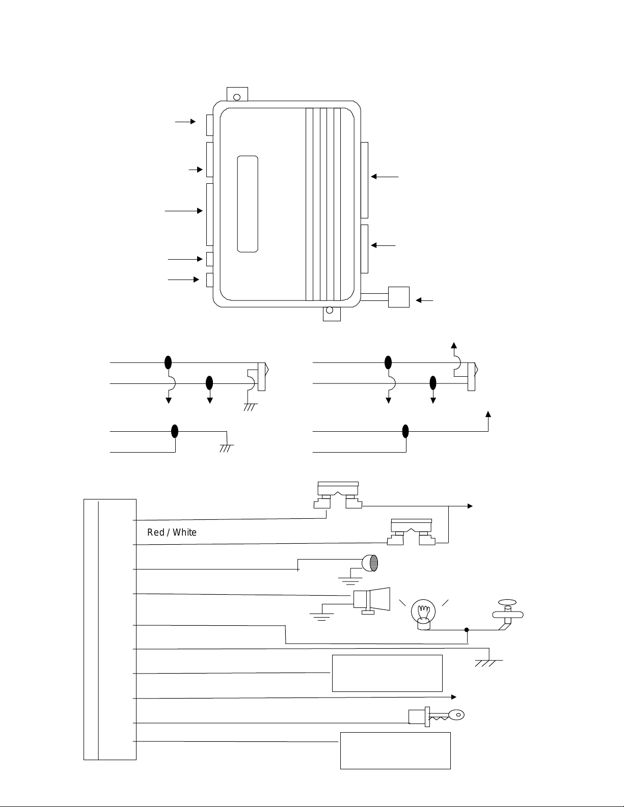
Antenna Plug
4 pin shock sensor
10 P in main ha rness
11 Pin P lu g
L.E.D. Plug
Override Plug
Negative door lock.
Green/white
Blue/white
Door lock Door unlock
Green/yellow
Blue/yellow
Red Wire: +12V To Fuse Box
Master
locking
switch
Po sit ive door lock .
Green/white
Blue/white
Door lock Door unlock
Green/yellow
Blue/yellow
3 A Fuse
1. Blue/yellow (N /O)--unlock.
2. Blue/red (N/C)--unlock.
3. Blue/white (C om)--unlock.
4. Green/white (Com)--lock.
5. Green/yellow (N/O)--lock.
6. Green/red (N/C)--lock.
2 wires start cut
+12V
Master
locking
switch
+12V
+12
10A Fuse
Red / White W ire: Parking light power
White wire :Parking Light Outpu
Brown Wire: To Siren
Li ght green wir e :Dom e Light Outp ut
Black Wire: To Ground
Li ght green wire :Dome Li gh t powe r
Gray Wire:Channel 2 (Trunk release) output
Y e llow Wire: To Ignition Switch
Gray Wire:Channel 2 (Trunk release) power
Parking li ght
Existing door pin switch
Dome Light
Entry il l um inat i on
Connect to +12V for + switch
or to ground for - switch
Connect to active
trunk release button
Tr unk r elease
Connect to +12V for + switch
or to ground for - switch
Page 2
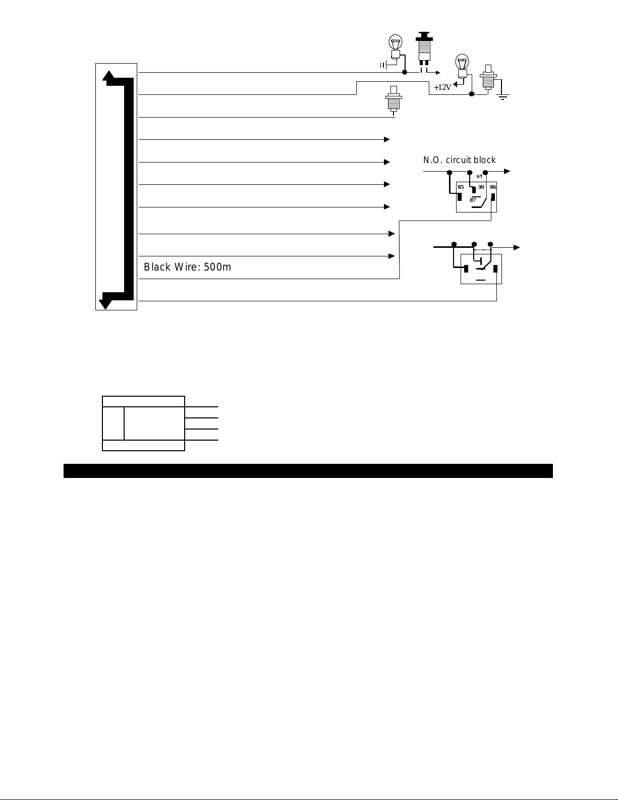
Violet Wire: Positive Door Pin Switch
g
(-)
(-)
(-)
g
n
+12V
Green Wire Negative Door Pin Switch:
+12V
Blue Wire: Instant Trigger Gr ound Input
Red Wire:
200mA channel 4 output
Gray Wire: (-) 200mA two step door unlock output
N.O. circuit block
White Wire:
Pink Wire: (- ) 200mA headlight output
200mA horn output
Cut
85 8630
87a
87
Yellow Wir e: (-) 200mA channel 3 output
Brown Wire:
200mA pager output
Black Wire : 500mA Grounded when disarmed
Oran
e Wire: 500mA Grounded when armed
N.C. circuit block
Cut
85 8630
87a
87
B. 2 PIN STARTER DISABLE PLUG:
This output can control starter disable, when an intrusion is detected and the system is triggered, the
vehicle is prevented from any unauthorized starting. Starter wires with 30 A relay built-in
C 4-PI N WHITE PLUG FOR ACCESSO RY DETECTIO N DEVICES
4. + 12V
3. Negative
2. Ground Trig
1. Warn Away I
PROGRAMMING & ADJUSTMENT
A. PROGRAMMING T RANS MITTER:
Maximum is 4 transmitters. Two modes of pr ogramming, one is designated channel, (Button 1 is arm/disarm)
the other is auto channel setting. (Button 1 is arm, button 2 is disarm.)
1. Enter:
Turn ignition to 'on' position. Within 15 seconds.
Push valet switch
3 times
1 long chirp to enter each channel's programming.
2. I n designated channel:
In program 1st tr a nsmit ter t he LE D will wit h one f las h…pa use s e q uence.
Press button 1 to program channel 1, 1 short chirp and LED on to confirm programmed and r eady program
channel 2.
Press button 2 to program channel 2, 2 short chirps and LED on to confirm programmed and ready
program channel 3.
Press button 3 to program channel 3, 3 short chirps and LED on to confirm programmed and ready
program channel 4.
Press button 4 to program channel 4, 4 short chirps and LED on to confirm programmed
Program 2nd tr a nsmit ter, p ush valet s witc h one time, the LED will wit h two fla s hes… p a use s e quence.
Press button 1 to program channel 1, 1 short chirp and LED on to confirm programmed and r eady program
channel 2.
Press button 2 to program channel 2, 2 short chirps and LED on to confirm programmed and ready
program channel 3.
to enter
designated
channel; if push
6 times
it will be
auto
channel .
2
Page 3

Press button 3 to program channel 3, 3 short chirps and LED on to confirm programmed and ready
program channel 4.
Press button 4 to program channel 4, 4 short chirps and LED on to confirm programmed
Program 3rd transmitter, push valet switch one time again, the LED will with three flashes…pause
sequence.
Use above steps to pr ogr am each channel.
Program 4th transmitter, push valet switch one time again, the LED will wit h fo ur flashes…p a use s e quence.
Use above steps to pr ogr am each channel.
3. In auto channel:
In program 1st tr a nsmit ter t he LE D will wit h one f las h…pa use s e q uence.
Press any butt on on 1st TX, 1 short chirp confirm programmed and ready program 2nd TX.
The LED will with two fla s hes… p ause s eq uence.
Press any butt on on 2nd TX. 1 short chirp confirm programmed and ready program 3rd TX.
The LED will with thre e flashes…pa use s e q uence.
Apply the same procedure to pr ogr am 3rd and 4th, after the 4th transmitter pr ogrammed the system w ill aut o
exit.
4. Exit:
Turn ignition to 'off' position, or leave it for 15 seconds. A 3 long chirps to confirm exit.
Note: If more than 4 transmitters programmed, the system only kept the last 4 transmitters.
!!! The designated channel & auto channel transmitters can exist independently.
This system has an unique optional passive/active transmitter design, it’s
•
programming is the same as above. (To see how it works, please see operation
part.)
B. PROGRAMMING OPT IONAL SENSOR (PIR OR DOOR/WINDOW S E NS OR)
This system has a very unique interfacing with optional sensor, to extend more protection, such as PIR (IR-70)
sensor or Door/Window sensor. (DS-70)
For example, in your garage you can put a PIR f or protection. (A device to detect person's movement in a
protected area.) I f syst em armed, a person walk through the detect area, the siren inside the car w ill a larming
to raise the attention to the owner.
So the same thing applies in door/window sensor, (A device to detect door /window open.) you may put the
sensor to the garage door or w indow. If system armed, a person opens the door or window, the siren will
alarm.
Maximum program 4 different sensor codes.
The programming procedure is the same as above A. PROGRAMMI NG TRANSMITTER of auto channel, The
difference is only upon enter you push the valet switch 9 times. (1 long chirp to confirm enters).
During prog ramming, you will need to act ivate the sensor to let the system program it's code.
C. PROGRAMMING F E ATURES:
There are 2 stages of totally 15 programming features to s elect. (Factory preset all features to "O N" position)
1. Enter:
Turn the ignition 'on' then 'off'. Within 15 seconds push the valet switch 6 times. (A long chirp.) It is on first
stage progr amming features.
2. First st age pr ogramming features:
Push the valet switch times that equal the feature number you want. Example: Push valet sw itch 2 times,
it' s o n chirp o n/o ff se lec tion. The sir e n w ill c hirp 2 times, L ED flash 2 time s to confir m e nte r this feature.
Select chirp on, turn ignition from 'off' to ‘on’. 1 chirp for confirmation.
Select chirp off, turn ignition from 'on' to ‘off’. 2 chirps for confirmation.
If you want to program transmitter car-jacking when the system is on chirp on/off, push valet switch 4 times
again. (Siren chirp 6 times, LED flash 6 times) The system will add on the previous valet sw itch pushing.
Note: Totally push valet switch 8 times, the siren chirp 8 times, and LED with 8 flashes… pause sequence.
If push the valet switch again, system will return to feature 1. (Siren chirp 1 time, and LED with 1
flash…pause sequence. It's cycling.)
3. Second stage programming features:
Enter: Again push & hold the valet switch for over 2 seconds, with 1 long chirp confirmation.
By using first st age pr ogr amming feat ures method to program second stage's f eat ures.
4. Exit:
3
Page 4

During programming, if you don’t respond to previous step in 15 seconds, or any time press t ransmitter’s
butt on 1, it w ill e xit feat ure s progra mming, which indicates by 3 lo ng chirp s .
FIRST STAGE:
Push valet
switch times:
Show 1 short chirp 2 short chirps
Select Feature " ON " Feature " OFF "
1 1 Curr ent sensor ON Curr ent sensor OFF
2 2 Chirp ON Chirp OF F
3 3 Active arming Passive arming
4 4 Rea rm ON Rearm OF F
5 5 When door close dome light on
6 6 Transmitter car-jacking OFF Transmitter car-Jacking ON
7 7 Ignition car-jacking OFF Ignition car-jacking ON
8 8 Door car-jacking OFF Door car-jacking ON
Chirp, par king
light flash times
Turn ignition from
'OFF' to 'ON'
(Vehicle e q uip interior light de la y )
No defective chirp reminder.
Turn ignition from
'ON' to 'OFF'
When door close dome light off
(Vehicle no inte rior light d e lay )
With defective chirp reminder.
SECOND STAGE:
Push valet
switch times:
Show One short chirp Two short chirps
Select Feature " ON " Feature " OFF "
1 1 Lock/unlock 0.8 sec. Lock/unlock 3.5 sec.
2 2 2- pulse unlock OFF. 2-pulse unlock ON.
3 3 Passive door lock ON Passive door lock OFF.
4 4 I gnition on door lock ON Ignition on door lock OFF
5 5 I gnition off door unlock ON Ignition off door unlock OFF
6 6 Disar m pa rking light OF F. Disar m pa rking light on 30"
7 7 Passw or d OFF. Password ON.
NOTE:
For system programming features all returns to presetting "ON", turn the ignition 'on' then 'off'. Within 15
seconds push the valet switch 3 times. (A long chirp.) Then press button 1 and 2 together for 5 seconds, there
will be a c o nfirmation long chirp.
Chirp parking
light flash times
Turn ignition from
'OFF' to 'ON'
Turn ignition from
'ON' to 'OFF'
D. T est ing sen sors:
In this test mode, t his system can test shock sensor sensitivity and other sensor. The installer can save time
to test the shock sensor sensitivity and sensor without using t he t raditional arming/disarming pr ocedures to
test the sensors.
ENTER:
1. System under disarm or valet condition.
2. Turn ignition switch on then off.
3. Within 15 seconds, push valet switch 3 times.
4. T her e will be a lo ng chirp c onf irmation to e nte r the test mode.
Trigger sensor Siren chirps
Negative pin switch 2
Voltage sensor 3
Optional wireless PIR or door switch 5
4
Page 5

TEST shock sensor:
1. Use channel 2 to enter. (pr ess butt on 2)
2. T her e will be a lo ng chirp c onf irmation fo r you to test s hock s e nsor.
3. Activate the warn away (first stage shock sensor), system will emit a short chirp.
4. Activate the full alarm (second stage shock sensor), system will emit a long chirp.
5. Continue to test t he shock sensor until reach the proper sensitivity.
TEST current sensor:
1. Use channel 3 to enter. ( pr ess butt on 3)
2. T her e will be a lo ng chirp c onf irmation.
3. Activate the current sensor, system will emit a s hor t chirp.
Note: In this test mode you may test both shock sensor and current sensor.
EXIT the test mode:
1. Turn ignition switch to on position or
2. Use channel 1 to exit. ( Pres s button 1)
There will be thr ee lo ng chirp s c o nfirm exit.
3.
E. Password set up: (MANUAL OVERRIDE RE - ARM FEATURE ON / OFF )
What is override re-arm:
An override re-arm feature designs as the system automatically re-arm in override condition, if the legal user
do not take correc t pr ocedures t o cancel the override re- ar m.
Programming your personal override re-ar m number:
In order to cancel override re-arm, you must program your personal number into the system. The number is
from 1 through 10, (by counting the LED flashing times) or you may use fact ory pre-set number 9 to cancel
override re-arm.
1. Program feature of pas sword to ‘ON’.
2. Enter system valet: Turn ignition key on then within 10 seconds push and hold override/valet switch for 2
seco nds, the LED will turns on.
3. Turn ignition key 'off-on' three times in 4 seconds. A confirmation long chirp from siren.
4. L ED will flas h f r o m 1 through 10 for 3 cycles. Wait until LED flash to your selected number.
5. As soon as LED turns on your selected number, quickly turn ignition key off.
6. A long chirp from siren, the number is programmed.
7. L ED will flas h t he pr o g rammed number for 2 cycles.
Example: To program override re- ar m number 5, you would;
1. Enter valet.
1. Turn ignition key 'off-on' three times in 3 seconds. A long chip from siren.
2. Wait until LED flash 5 times, then quickly turn ignition key off. A long chirp from siren.
3. L ED will flas h 5 t ime s to indicate y o ur o ver ride re - a rm number is 5.
OPERATION
A. TR ANSMI TTER OPER ATION :
For designated channel setting:
Transmitter Button System Function Remark
Button 1 Arm/disarm & door lock/unlock
Button 1 Panic function Press 3 sec
Button 1 - 1 Arm and delete optional sensor In disarm, press twice.
Button 1 - 1 Two step door unlock In arm, press t w ice.
Butt on 2 Cha nnel 2 (trunk) control Press 2 sec.
Button 2 - 2 Passive arming by-pass Under passive arming press tw ice.
Button 2 - 2 Car locator Press twice.
Butt on 3 Cha nnel 3 control
Button 4 Panic Press 1 second.
5
Page 6

Button 1 + 2 both Silent arm/disar m Ignition in "off" position.
Button 1 + 2 both 1 sec Act ivate car- jacking Ignition in 'on' position and
Programmed transmitter carjacking "ON"
Button 2 + 3 both Channel 4 control
Side button Switching code system
For auto channel setting:
Transmitter Button System Function Remark
Button 1 Arm & door lock
Button 1 Panic function Press 3 sec.
Button 1 - 1 Arm and delete optional sensor Press tw ice.
Button 2 Disarm & door unlock
Button 2 -2 Two st eps door unlock Press twice.
Butt on 3 Cha nnel 2 (trunk) control Press 2 sec.
Button 3 - 3 Passive arming by-pass Under passive arming press tw ice.
Button 3 - 3 Car locator Press twice
Button 1 + 3 both Channel 3 control
Button 4 Panic Press 1 seconds.
Button 1 + 2 both Silent arm/disar m Ignition in "off" position.
Button 1 + 2 both 1 sec. Activate car-jacking Ignition in 'on' position and
Programmed transmitter carjacking "ON"
Button 2 + 3 both Channel 4 control
Side button Switching code system
B. UNIQUE O PTIONAL PASSIVE/ACTIVE T RANSMIT TER :
This system has a passive/active transmitter (PT) design that allows you to arm/lock and disarm/unlock the
system passively or actively. The active usage is the same as above operation. Below is the passive
operation:
1. Slide the passive switch to ‘ON’ position on the front case.
2. When you move toward your vehicle around 10 meters, system will automatically dis a rm and unlock the
doors.
3. When you leave your vehicle over 10 meters, and after 10 seconds system will automatically arm and
lock the doors.
4. In case the system armed and lock all doors, while you leave your ignition key and this transmitter inside
the vehicle. Ro c k the vehicle the transmit ter will disar m and unlock t he do o r s .
Note:
1. Time delay:
Upon you are active pressing the button on the transmitter, the system will set a 60 sec o nds time delay
for the pas s ive f e a ture. Fo r example you pre s s a ny button on the tr a nsmit ter, t he pas s ive featur e will not
works in 60 seconds.
2. Turning the Passive System Off
You can disable t he pas s ive featur e b y moving the t ransmitt e r 's slider switch to O F F. It will t urn into
normal active transmitter.
C. LED DISPL AY :
LED Function LED Function
Off Disarmed 2 flashes... pause Trigger on trunk/hood
Slow flash Armed 3 flashes... pause Trigger on door swit ch
Fast flash Passive arming 4 flashes... pause Trigger on sensor
On (solid) Valet mode 5 flashes... pause Trigger on PIR Door / window sensor
6
Page 7

D. CHIRP INDICATO RS :
Chirp Function
1 chirp Arm
2 chirps Disarm
3 chirps Defective reminder
4 chirps Disarm / Trigger ed
6 chirps Ca r locat o r
E. PARKING LIGHT :
Park ing light F unction
1 flash Ar m
2 flashes Disarm
3 flashes Disarm / Triggered
5 flashes Transmitter low battery.
(suitable for random code only)
12 flashes Car locator
F. OVERRIDE/VALET SW ITCH :
1. OVERRIDE FUNCTION: (Syst e m in arm c o ndit io n)
Use in emergency, like lost or malfunctions of transmitter. Turn ignition on, within 10 seconds push the
overr id e /valet switch, the siren will s top and the syst em disarmed.
2. VA LE T MODE: (Syst e m in disarm condition)
Vehicle in for maintenance or valet parking, the system will not a rm.
a. Turn ignition on then within 10 seconds push and hold override/valet switch for 2 seconds, t he LED w ill
turns on indicates the system is in 'valet mode'.
b. System stay in 'valet mode', t ransmitter st ill can remot e operating lock or unlock the doors, parking
light, pop t r unk release and panic function. But no alarm function.
c. Return to normal operation, turn ignition 'on', then within 10 seconds, push and hold override/valet
sw itch for 2 s e c o nds, it w ill e xit the valet.
G. PASSIVE ARMING :
It oper at e as below:
1. Turn 'off' the ignition.
2. Leave vehicle and close all doors.
3. LED fast flashing.
4 After 30 sec. Sys t em auto arming
Note: during the 30 sec. If open the door the time will sto p counting dow n, until all doors closed then again
re-start count down for 30 sec.
Passive arming by-pass: Press button 2 twice (designated channel setting), to temporally by-pass
pass ive arming. That' s for prevent locking yo urs e lf out of the vehicle ( F or example fill up the gas).
A short chirp w ill c o nfirm this by- p a s s .
Re-open the door will not start t he passive arming again.
Note: It’s only temporally by-pass. When turn ignition ‘on - off ‘ or use transmitter to arm or disarm, this bypass will cancel.
H. AC TIVE ARMI NG :
1. Press ar m button on transmitter.
2. T he siren will chirp o nce a fter 3 s e c onds the system will be fully arm.
NOTE: Defective sensor reminder: 3 chirp indicate defective sensor occurred.
Special Note: If the system is interfacing with optional sensor, such as PIR or door/w indow sensor, upon
system armed, if the PIR or door sensor tr iggered, t he system will full alarming.
7
Page 8

I. ACTIVE DISARMING :
1. Press disarm button on the transmitter.
2. T he siren will chirp twice to indicat e that system disarmed.
NOTE: 1. Tamper disarming: If alarm triggered, upon disarm the system, siren chirp 4 times,parking light
flash 3 times.
NOTE: 2. Automatic re-arm: No doors open and no ignition on after disarm; aft er 60 seconds system auto
rearm.
J. PANIC FUNCT ION :
The transmitter can be used as a remote panic switch to manually tr igger the alarm in case emergency. To
do so, hold button 4 for 1 second, and the system will full alar ming. To st op panic, pr ess b utto n 4 again or
press disarm button.
K. TRIGGER THE SYSTEM :
While system in armed condition, open the doors, hood, trunk or trigger the optional sensors, siren and
par king light will t urn on to ale rting of an intr usion for 30 or 60 s econds. Then it will stop and automat ic
res et and re-a rm. If the one of senso rs o r de tec to rs s till a ctive, t he alarm system will s ound a maximum of
3 times of 30 or 60 seconds cycles.
L. DO ME LIGHT CONVENIENCE DELAY & SUPERVISION :
Upon disarming, the dome lights will remain on for 30 sec o nds.
If t he vehicle triggered, the dome light will flashing as the sa me d ura tion as sire n.
Note: Turn on the ignitio n switch or a r m the alarm w ill turn off the dome light.
M. ANT I CAR-JACKING :
Warning: If you don't want t o have car jacking in this alarm system, be sure to set car - jacking off.
This system is default sett ing all car-jacking OFF.
In this system totally there are 3 feat ur es of ent er ing car- jacking.
First: Use transmitter to enter car-jacking. (Program transmitter car-jacking ON, see programming
features)
This feat ur e pr ovides user t o remote act ivates car - jacking. When pr ogr ammed this featur e O N,
upon the ignition switch is 'on', user can pr ess but t on 1 + 2 t ogether for 1 second to ent e r car jacking.
Second: Use ignition switch turn to 'on' position to enter car-jacking. (Program ignition car-jacking ON, see
programming features) . This feature provides user t o use ignition switch to activate car - jacking.
When programmed this featur e O N, upon t ur n t he ignition switch to 'on' position, t he syst em enter
car-jacking.
Third: Use Door open close t o enter c ar - jacking. (Program door c ar - jacking ON, see programming
features)
This feat ur e pr ovides user t o use door open close t o act ivates car - jacking. When pr ogr ammed this
featur e O N, upon t he ignition switch is 'on', if someone open door and close door t he syst em enter
car-jacking.
2-timer circuits w ill funct io n as follow s :
First timer:
50 se conds af t er a ctivat es c ar -jac king. The s iren will s ta rt chirping. Wit hin 10 seconds, you w ill be aler t
to turn the ignition switch from off to on, and push valet switch to turn off the car jacking feature. If not, it
will ent e r s e c o nd t imer car jac k ing.
Second timer:
Totally after 60 seconds from beginning, siren still alarming and parking light flashing, and the starter
disable will act ivate to prevent the vehicle from starting. Override the system to turn off car jacking.
(Ignition from off to on, and w ithin 10 seconds push valet switch)
8
Page 9

Note: If you use pass word (see below Passw ord Secur ity) to double protect t he vehicle secur ity, you will
need to use it to completely disarm the system.
N. PASSWO RD SE CURITY :
In carry this feature you need to set features programming of password 'ON' first. Then program your
passwor d number. Please see above PROGRAMMI NG section.
Using password to protect system. Below is an example of how to use password to completely
disarm system.
System in arm condition.
1. Open the door, siren will so und.
2. Turn ignition key on.
3. Push valet switch.
Note: When finished above procedures, system's siren stop alarming, parking light stop flashing, other
sensor stop tr igger, but t he vehicle can not be start and drive away.
Use password to cancel the system re-arm: ( Re-a rm timer 30 seconds)
When system disarmed, the LED start flashing, indicate system entered passwor d procedures.
Cancel system re-arm itself:
Wait until LED flash to your password number, then turn the ignition key 'on-off', to cancel re-arm.
You must make sure to turn the ignition key off at the correct number within 30 seconds. If not, the system
will aut o matically r e -arm.
Example: To cancel re-arm using password number 5 of above, you would;
1. Open the door. Siren sound.
2. Turn ignition key on.
3. Push valet switch.
4. Wait LED flash 5 times, then quickly turn ignition key off.
Note 1: The number is form 1 through 10, by counting LED f lash. Legal user can program the number.
Note 2: If some one tur n the ignition key off at wrong override number, the system allows him to make 2
mista k es , if t hir d time st ill wrong, it will auto matically s hut down for 3 minutes . During the period the system
will not accep t any corr ect number , and when time is up it w ill re- armed aga in; w hich wit h siren one chirp
and parking light one flash, LED flashing, door locked and activate sensors to guard the vehicle.
O. IG NITION CONTROL PO W ER DO OR LOCK SAFETY SYST EM :
The vehicle's doors w ill a utomat ically lo ck a ft er the ignition ke y tur n 'on' (if all doors ar e closed.) And when
the ignition key turn 'Off', the doors w ill a uto matically unlock.
P. TRUNK RELEASE :
Press and hold button 2 on t r ansmitter f or t wo seconds to remote control t he t r unk release or other elect r ic
devices.
Q. CHANNEL 3 CONTRO L :
Press button 3 (designated channel setting), or button 1+3 together (auto channel setting) to remote control
the optional elect rical device . The device w ill ' o n' when the button(s ) pres s c o ntinuously, a nd ' off' when the
button(s) released.
R. CAR LOCATOR :
Press button 2 twice (designated channel setting), or button 3 twice (auto channel setting) to active car
locat or function. The sire n w ill chirp 6 t imes. The pa rking light w ill flash 12 t imes, fo r you to e asily loca te
your car.
S. T RANSMITTER LOW BATT ERY : ( Random code transmitter only)
When the transmitter is in low batter y condit ion, the system will show up by par king light fla sh 5 times, to
remind the user to change t he low batt er y .
T. TWO STEPS DO OR UNLOCK :
9
Page 10

Upon first disarming, the system only unlock the driver ' s side door. Then press t he disarm button again, t he
system will unlock all the doors.
U. ALARM OPERATING CONDITION:
Siren, horn Parking Light LED Doors Start er
disable
1. Arming 1 Chirp 1 Flash Slow flash Locking On
2. Disarming 2 or 4 Chirps 2 or 3 Flashes Fast f lash (in passive arming) or
OFF.
3. Trigger Alarming Flashes Slow f lash On
4. Panic Alarming Flashes Slow flash Locking
5. Car-J acking Alarming Flashes Slow f lash On
6. Car locator 6 chirps 12 flashes
This device complies with part 15 of the FCC rules. Operation is subject to the following two conditions.
(1) This device may not cause har mful interf er ence, and
(2) This device must accept any interference received, including interference that may cause undesired
operation.
Unlocking Off
10
 Loading...