

Page 1
A1
A2
A3
A4
A5
A1A2A3A4A5
A1A2A3A4A5
Quick Start Guide
1
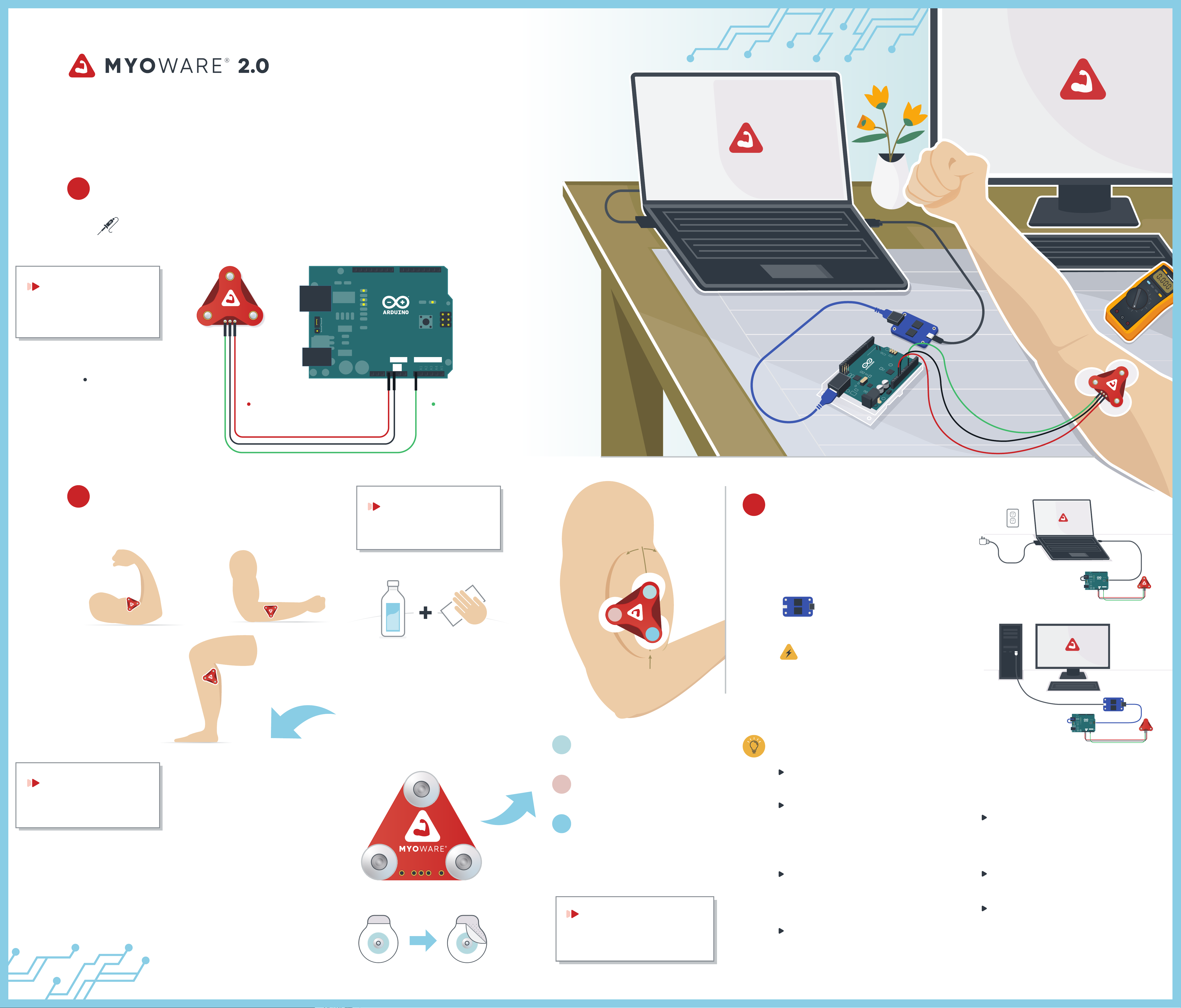
Connecting the sensor to an Arduino
Solder wiring of your choice (or connectors such as
header pins) to the Vin, GND, and ENV pins on the sensor.
QUICK TIP
Using a multimeter, verify that
your solder joints are making a
good connection.
USB
EXT
PWR SEL
6ND
AREF
2 1 0 9 8 7 6 5 4 3 2 1 03
1 1 1 DIGITAL1
L
TX
RX
PWR
PWR
PWR
PWR
PWR
PWR
TX
RX
PWR
1
IC3P
Connect the GND wire
to one of the Arduino's
GND pins
IOREF
Connect the Vin pin
to the Arduino's 5V or 3V pin
5V
RESET
3.V3
POWER
GND
VIN
ANALOG IN
A0
Connect the ENV wire
to one of the Arduino's
analog input pins (e.g. A0)
DIGITAL
2 1 0 9 8 7 6 5 4 3 2 1 03
6ND
AREF
2
Placing the sensor
Determine which muscle group you want to target:
FOREARM
QUICK TIP
Start with the bicep until you
get the sensor working properly.
Bicep muscle body
A
B
3
Connecting the sensor
Connect the Arduino to a computer using
a USB cable. If using a laptop, the laptop's
power cord must be disconnected from
the wall unless a USB isolator is used.
If using a desktop, a USB
isolator is ALWAYS required.
LAPTOP
2 1 0 9 8 7 6 5 4 3 2 1 03
6ND
1 1 1 DIGITAL1
AREF
TX
RX
PWR
PWR
PWR
PWR
PWR
PWR
L
TX
PWR
RX
USB
EXT
PWR SEL
1
IC3P
POWER
ANALOG IN
GND
5V
A0
RESET
IOREF
3.V3
VIN
BICEP
RECOMMENDED
NOTE
Muscle groups not to scale.
CALF
Thoroughly clean the intended area
with rubbing alcohol to remove dirt
and oil and allow to dry.
NOTE
Soap can leave residue and should be avoided.
Body hair can cause a poor connection. Use areas
with sparse hair or remove hair from the area.
A
C
Middle of muscle body
Place the MID electrode in
the middle of the muscle body
ELECTRICAL SHOCK WARNING
A USB isolator ensures separation between the body
and the power grid to safeguard against any
chance of electrical shock. The USB isolator also
reduces noise in the output signal caused by some
countries' power grid.
Troubleshooting Tips
DE SKTOP
2 1 0 9 8 7 6 5 4 3 2 1 03
6ND
1 1 1 DIGITAL1
AREF
TX
RX
PWR
PWR
PWR
PWR
PWR
PWR
L
TX
PWR
RX
USB
EXT
PWR SEL
1
IC3P
POWER
ANALOG IN
GND
5V
A0
RESET
3.V3
IOREF
VIN
QUICK TIP
Never reuse single-use
electrodes (e.g. the ones we sell)
Snap electrodes to the sensor’s
three snap connectors marked
MID, END, and REF.
NOTE
We do not recommend snapping the MyoWare to
the electrodes after they've been placed on the skin,
doing so can cause bruising!
REF
REF
VNI
MID
END
VIE
DNG
MID END
B
Place the REF electrode
adjacent to the muscle body
C
Place the END electrode lined up
in the direction of the muscle length
NOTE
The depiction above is not to scale.
The Vin LED should remain on constantly as
long as the sensor is powered.
The ENV LED might immediately turn on
when power is turned on but it should turn
o after a second or two; afterwards, it
should only turn on when the sensor detects
muscle exion.
The ENV LED might sporadically turn on and
o or simply remain on if the sensor (or external cables) is not connected to electrodes
between the electrodes and the skin.
Try cleaning the area and applying
new electrodes.
The ENV LED not lighting up during exion
could be caused by various issues with the
sensor setup. Double check the steps and
tips of this guide to ensure proper setup.
Most of the time the sensor gain does not
need to be adjusted at all.
Recommended that you do not adjust the
Peel off the backs of the electrodes
QUICK TIP
on the skin. This is normal behavior.
sensor’s gain until you get a consistent,
to expose the adhesive and attach
the MyoWare sensor to the muscle:
Placement is extremely important.
If this isn’t clear, please reference the
Advanced Guide for more information.
The ENV LED lighting up seemingly at
random while connected to electrodes on
quality signal from the sensor
the skin usually indicates poor contact
© 2022 Advancer Technologies LLC
US Pat . 1,0010,259
www.myoware.com/patents
 Loading...