

Page 1

User Manual
CDD530AM-002; WBR-6603
WiFi ADSL2/2+ Router
1
Page 2

Copyright
The contents of this publication may not be reproduced in any part or as a whole, stored,
transcribed in an information retrieval system, translated into any language, or transmitted in any
form or by any means, mechanical, magnetic, electronic, optical, photocopying, manual, or
otherwise, without the prior written permission.
Trademarks
All products, company, brand names are trademarks or registered trademarks of their respective
companies. They are used for identification purpose only. Specifications are subject to be changed
without prior notice.
FCC Interference Statement
This equipment has been tested and found to comply with the limits for a Class B digital device
pursuant to Part 15 of the FCC Rules. These limits are designed to provide reasonable protection
against radio interference in a commercial environment. This equipment can generate, use and
radiate radio frequency energy and, if not installed and used in accordance with the instructions in
this manual, may cause harmful interference to radio communications. Operation of this
equipment in a residential area is likely to cause interference, in which case the user, at his own
expense, will be required to take whatever measures are necessary to correct the interference.
CE Declaration of Conformity
This equipment complies with the requirements relating to electromagnetic compatibility, EN
55022/A1 Class B.
2
Page 3

TABLE OF CONTENTS
COPYRIGHT...................................................................................... ................................... 2
FCC INTERFERENCE STATEMENT............................................................... .... .... ... .... .....2
1.1 PACKAGE LIST........................................................................................................... 4
1.2 HARDWARE INSTALLATION.................................................................................... 5
CHAPTER 2. GETTING STARTED......................................................................................8
2.2 EASY SETUP BY CONFIGURING WEB PAGES.............................................. .......... 12
CHAPTER 3. MAKING CONFIGURATION.....................................................................16
3.1 START TO CONFIGURE .......................................................................................... 16
3.2 SYSTEM STATUS...................................................................................................... 17
3.3 ADVANCED ............................................................................................................... 18
3.3.1 BASIC SETTING......................................... ...............................................................18
3.3.2 FORWARDING RULES.............................................................................................32
3.3.3 SECURITY SETTINGS............................................................................ ..................36
3.3.4 ADVANCED SETTINGS............................................................................................50
3.3.5 TOOLBOX..................................................................................................................61
CHAPTER 4. TROUBLESHOOTING.................................................................................66
APPENDIX A. SPEC SUMMARY TABLE..........................................................................70
3
Page 4
CHAPTER 1. Introduction
Congratulations on your purchase of this outstanding product: CDD530AM-002 WiFi ADSL2/2+
Router. This product is specifically designed for home and small office needs. It provides a
complete solution for Internet surfing. Instructions for installing and configuring this product can be
found in this manual. Before you install and use this product, please read this manual care fully for
fully exploiting the functions of this product.
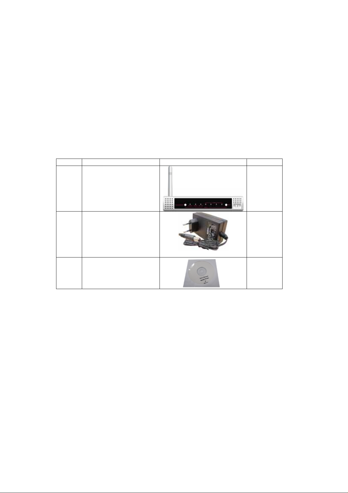
1.1 Package List
Items Description Contents Quantity
1 WiFi ADSL 2/2+ Router 1
2
Power adapter 12V 0.6A
3
CD
1
1
4
Page 5
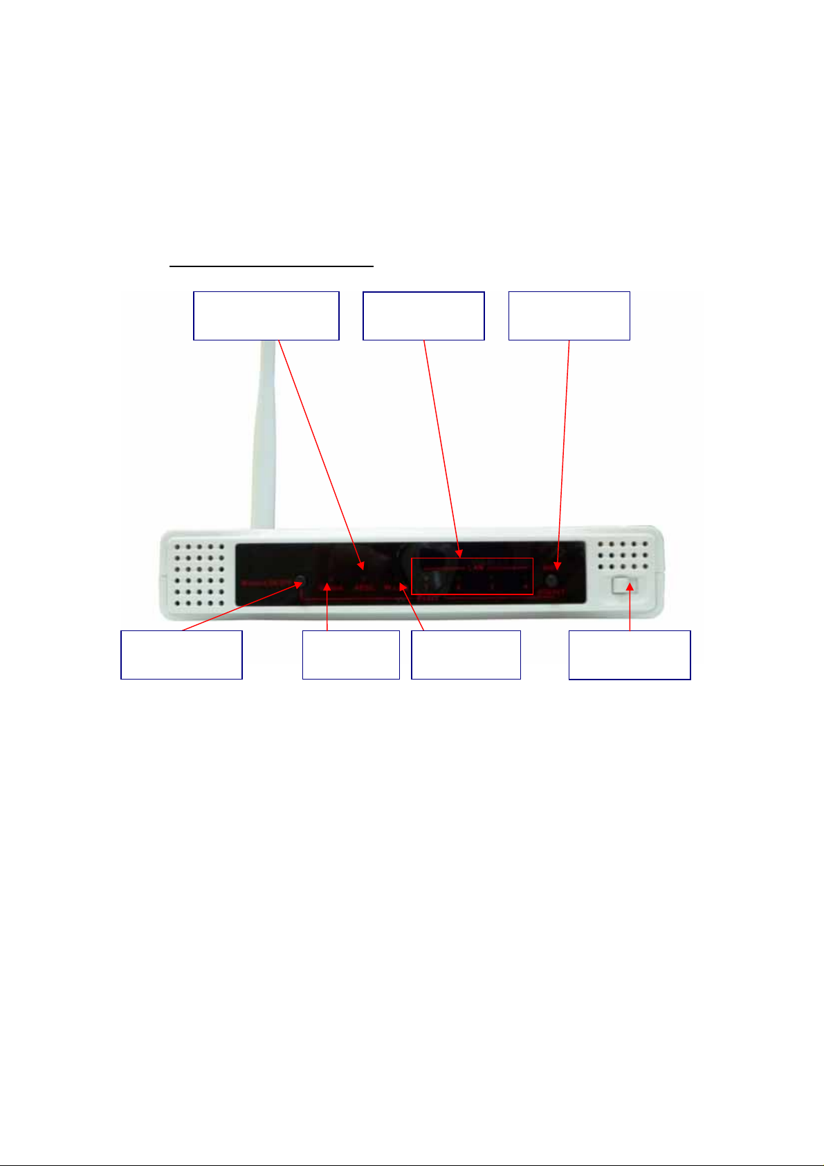
1.2 Hardware Installation
1.2.1 Hardware configuration
Wireless
On/Off Button
ADSL Connection
Status
Status LED Power Switch WLAN LED
LAN1~LAN4
LEDs
WPS Button
Reset: Press “Wireless on/off ” an d “ WPS” button for 5 sec simultaneously.
5
Page 6
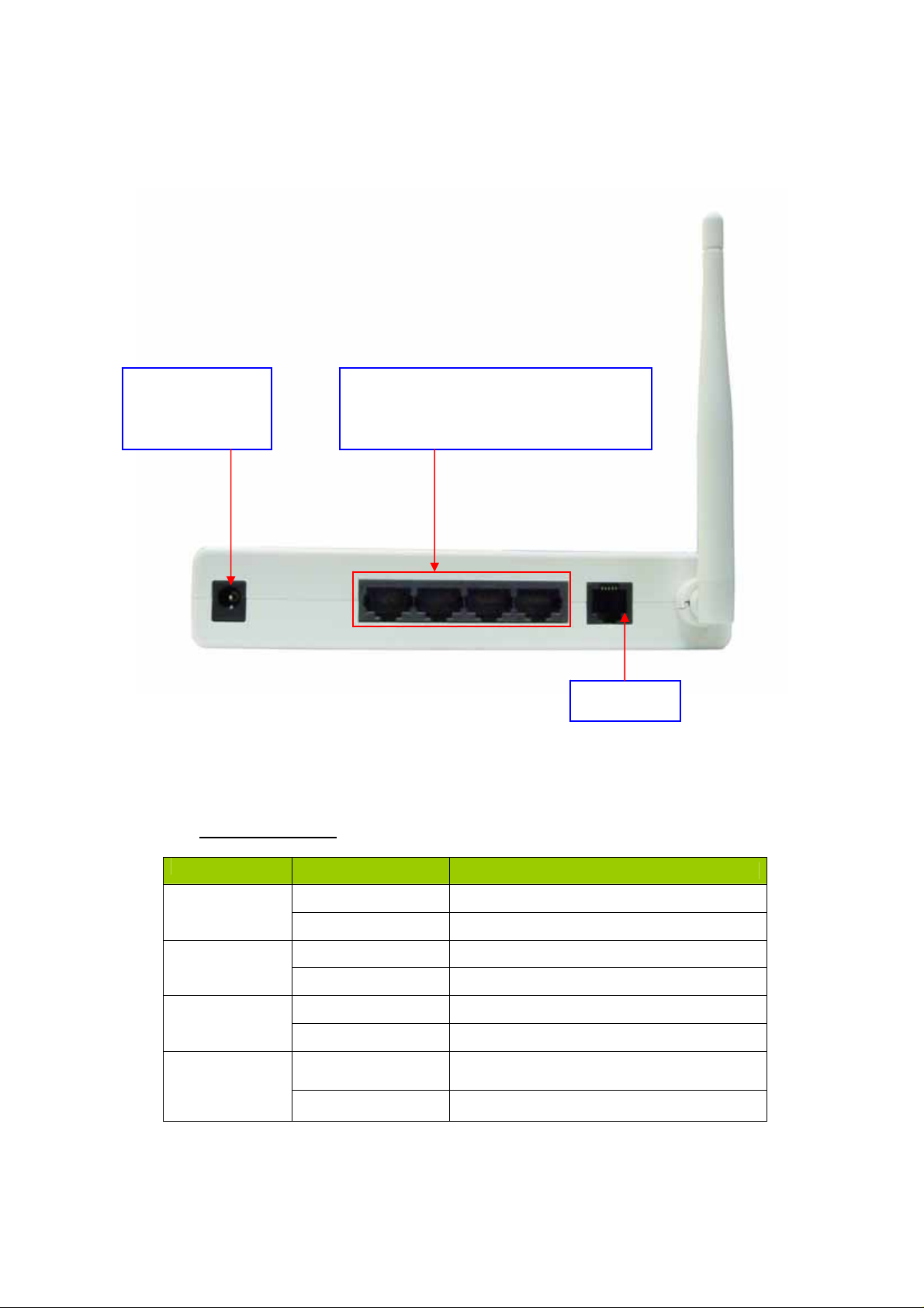
Receptor for
Power adapter
1.2.2 LED indicators
Auto MDI/MDIX RJ-45 Po rts
Automatically sense the types of WA N
and LAN when connecting to Ethernet
LED color Description
RJ-11 Port
Status
ADSL
WLAN
LAN
Green in flash power is on
Green in fast flash Reset mode
Green in flash xDSL connection is established
Green in fast flash Data packet transferred via DSL Line
Green WiFi is on.
Green in flash Data access
Green
Green in flash Data access
RJ45 cable is plugged, and Ethernet
connection is established.
6
Page 7
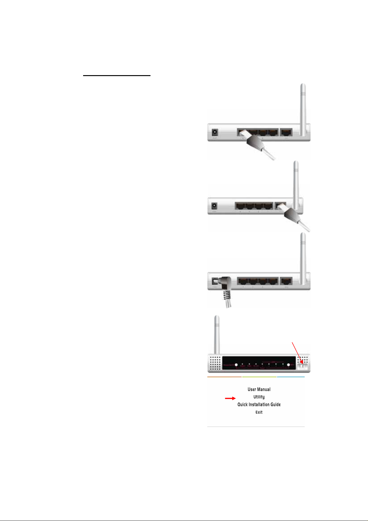
1.2.3 Installation Steps
Step 1. Connect with the Ethernet patch cable:
Insert the Ethernet cable into RJ45 Ethernet Port on
the back panel. And then plug the other end of RJ45
into the computer or Laptop computer. The LED of
Internet connection will show green color if the
Ethernet connection is normally connected.
Step 2. Insert the RJ11 cable for ADSL
Step 3. Connect the power adapter:
Plug the other end of the power adapter into a wall
outlet.
Step 4. power on
Switch the power on in front of this WiFi ADSL Router
Step 5. Start to configure the device:
You can start to configure the device via the Easy
Setup.
(see Easy Setup Utility)
7
Page 8

CHAPTER 2. Getting Started
2.1 Easy Setup by Windows Utility
Step 1:
Install the Easy Setup Utility from CD
then follow the steps to configure it.
Step 2:
Select Language then click “Next” to
continue.
Step 3:
Then click the “Wizard” to continue.
Or click “advanced” to run advanced
mode for more detailed setting.
(See User Manual)
Step 4:
Click “Next” to continue.
8
Page 9

Step 7:
Configure your wireless interface.
Step 8:
Insert SSID, Channel and Security
options, and then click “Next” to
continue.
Step 9:
Auto detect the WAN service, just click
the [Next] button.
Or you could select the WAN type by
yourself via select the check box [Let me
select WAN service by myself] Æ jump
to Step 10.
9
Page 10
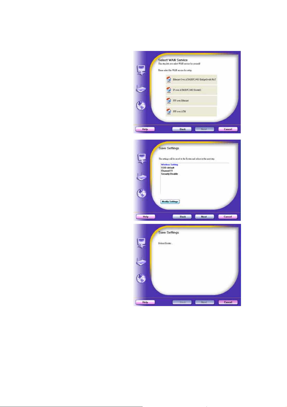
Step 10:
Select the WAN type by yourself. You
can get this information by asking your
ISP.
Step 12:
The WiFi ADSL Router is rebooted to
make your entire configuration take
effect.
Step 13:
Click “Next” to test the Internet
connection.
10
Page 11

Step 14:
Click “Next” to test WAN Networking
service or you can ignore test.
Step 15:
Congratulations!
Setup is completed.
Now you have already connected to
Internet successfully.
11
Page 12
2.2 Easy Setup by Configuring Web Pages
You can also browse UI of the web to configure the device.
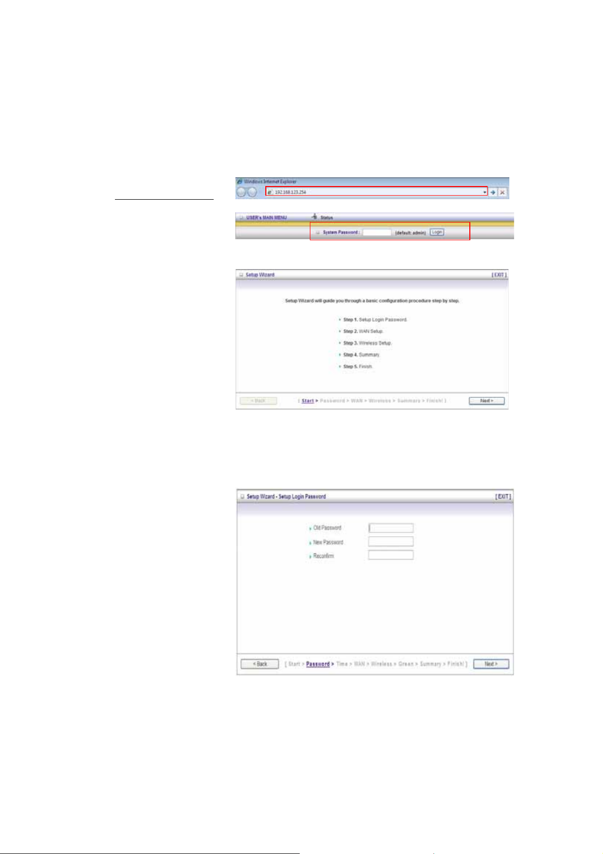
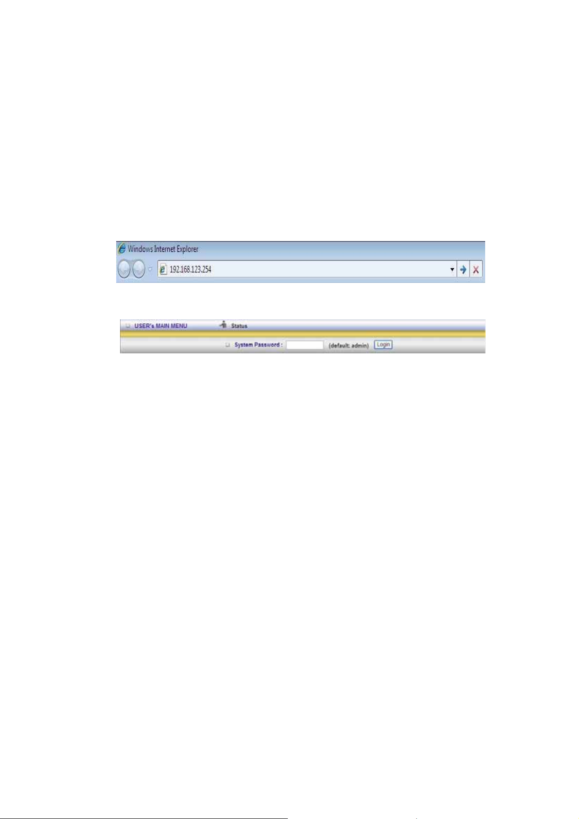
Browse to Activate the Setup Wizard
Type in the IP Address
(http://192.168.123.254
Type the default
password ‘admin’ in the
System Password and
then click ‘login’ button.
Select “Wizard” for basic
settings in simple way.
Press “Next” to start the
Setup Wizard.
)
Configure with the Setup Wizard
Step 1:
Setup login password.
Enter your system
password.
12
Page 13
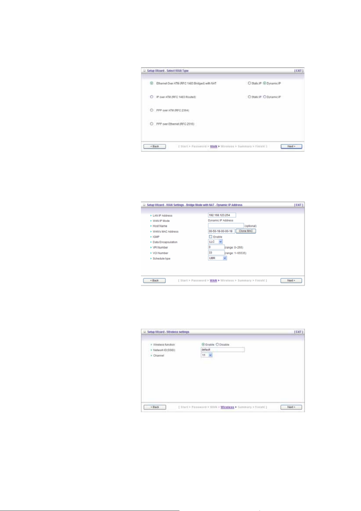
Step 2:
Setup Wan Type.
Step 3:
Type in WAN information
and go ‘next’ step.
Step 4:
Wireless Set up.
13
Page 14
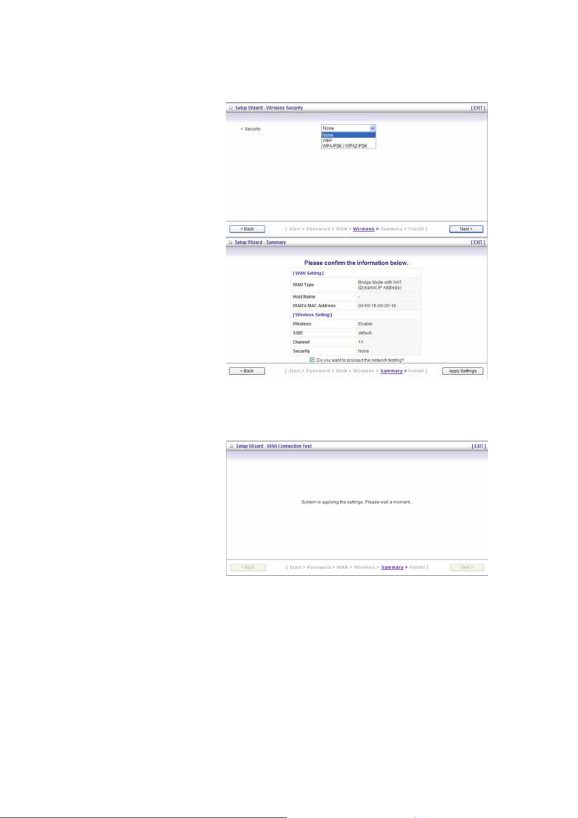
Step 5:
Wireless security setup.
Step 6:
Confirm your information
and apply the settings.
Step 7:
Setup completed.
14
Page 15
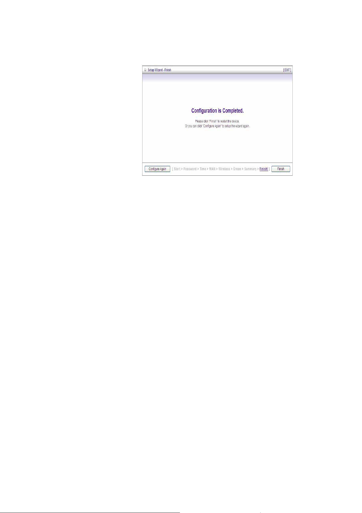
Step 8:
Click Finish to complete it.
15
Page 16
CHAPTER 3. Making Configuration
3.1 Start to configure
Whenever you want to configure your network or this device, you can access the
Configuration Menu by opening the web-browser and typing in the IP Address of the
device. The default IP Address is: 192.168.123.254.
Enter the default password “admin” in the System Password and then click ‘login’ button.
Afterwards, select ‘Advanced’ indicated in the user interface for further configuring this
device. In the “Advanced” page, it could be categorized four sections, respectively Basic
Setting, Forwarding Rules, Security Setting, and Advanced Setting.
16
Page 17
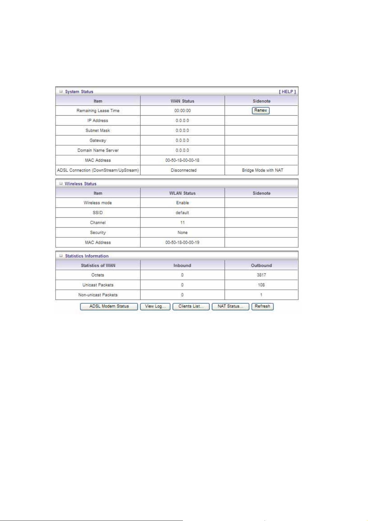
3.2 System Status
This option provides the function for observing this product’s working status:
WAN Port Status.
If the WAN port is a ssig ned a dyn amic IP, there may appear a “Renew” or “Release” button on the
Sidenote column. You can click this button to renew or release IP manually.
Statistics of WAN: enables you to monitor inbound and outbound packets
17
Page 18
3.3 Advanced
3.3.1 Basic Setting
Please Select “Advanced Setup” to Setup
3.3.1.1 Primary Setup – WAN Type, Virtual Computers
18
Page 19
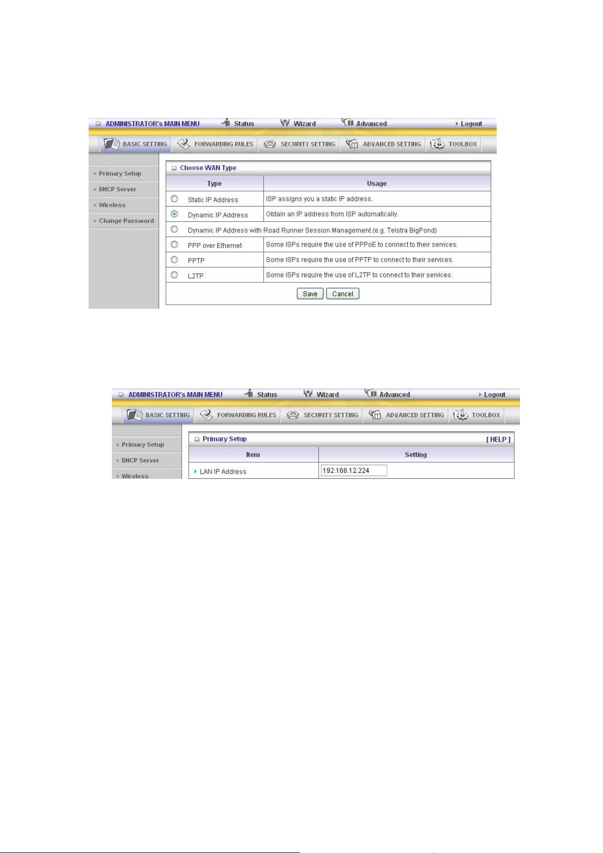
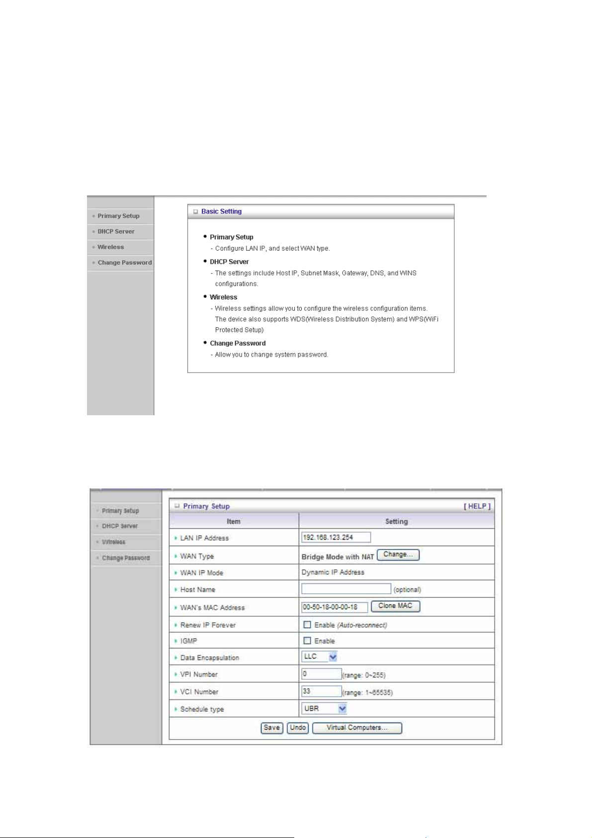
Press “Change” on WAN type to change the type you want.
This option is primary to enable this product to work properly. The setting items and the web
appearance depend on the WAN type. Choose correct WAN type before you start.
1. LAN IP Address: the local IP address of this device. The computer s on your network must
use the LAN IP address of your product as their Default Gateway. You can change it if
necessary.
2. WAN Type: WAN connection type of your ISP. You can click Change button to choose a
correct one from the following four options:
A. Static IP Address: ISP ass igns you a static IP address.
B. Dynamic IP Address: Obtain an IP address from ISP automatically.
C. PPP over Ethernet: Some ISPs require the use of PPPoE to connect to their services.
D. PPTP: Some ISPs require the use of PPTP to connect to their services.
F. L2TP: Some ISPs require the use of L2TP to connect to their services
Static IP Address: ISP assigns you a static IP address:
WAN IP Address, Subnet Mask, Gateway, Primary and Secondary DNS: enter the proper setting
provided by your ISP.
19
Page 20
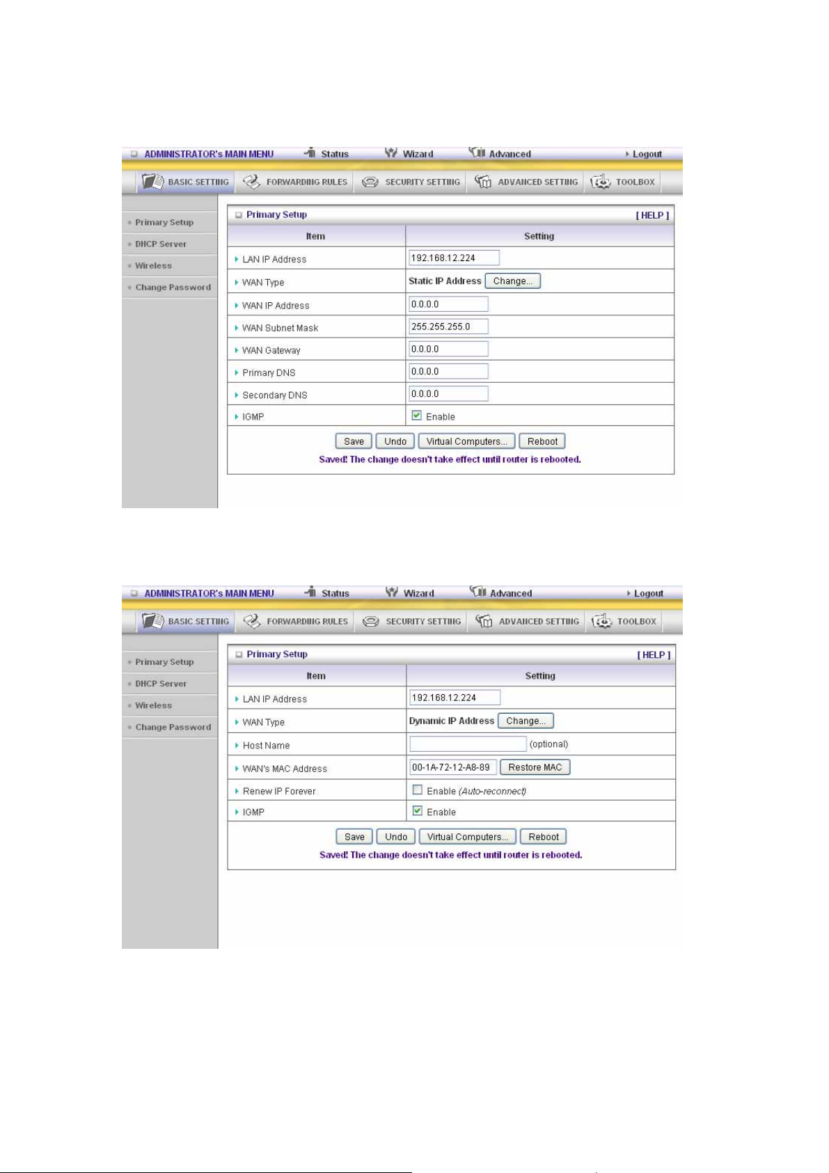
Dynamic IP Address: Obtain an IP address from ISP automatically.
Host Name: optional. Required by some ISPs, for example, @Home.
Renew IP Forever: this feature enables this product to renew your IP address automatically when
the lease time is expiring-- even when the system is idle.
PPP over Ethernet: Some ISPs require the use of PPPoE to connect to their services.
PPPoE Account and Password: the account and password your ISP assigned to you. For security,
this field appears blank. If you don't want to change the password, leave it empty.
PPPoE Service Name: optional. Input the service name if your ISP requires it. Otherwise, leave it
blank.
20
Page 21
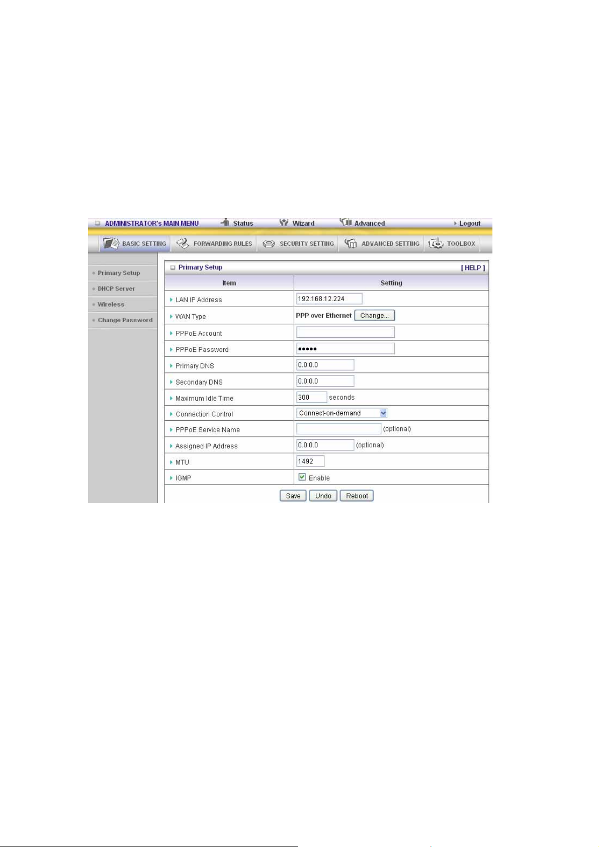
Maximum Idle Time: the amount of time of inactivity before disconnecting your PPPoE session.
Set it to zero or enable Auto-reconnect to disable this feature.
Maximum Transmission Unit (MTU): Most ISP offers MTU value to users. The most common
MTU value is 1492.
Connection Control: There are 3 modes to select:
Connect-on-demand: The device will link up with ISP when the clients send outgoing packet s.
Auto-Reconnect (Always-on):The device will link with ISP until the connection is established.
Manually :The device will not make the link until someone clicks the connect-button in the
Status-page.
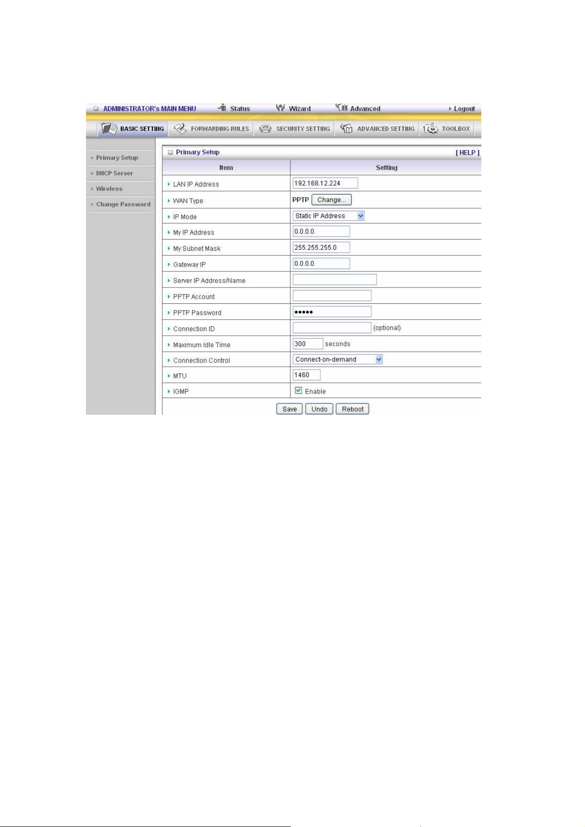
PPTP: Some ISPs require the use of PPTP to connect to their services
First, please check your ISP assigned and Select Static IP Address or Dynamic IP Address.
1. My IP Address and My Subnet Mask: the private IP address and subnet mask your ISP
assigned to you.
2. Server IP Address: the IP address of the PPTP server.
3. PPTP Account and Password: the account and password your ISP assigned to you. If you
don't want to change the password, keep it empty.
4. Connection ID: optional. Input the connection ID if your ISP requires it.
5. Maximum Idle Time: the time of no activity to disconnect your PPTP session. Set it to z ero or
enable Auto-reconnect to disable this feature. If Auto-reconnect is enabled, this product will
connect to ISP automatically, after system is restarted or connection is dropped.
Connection Control: There are 3 modes to select:
Connect-on-demand: The device will link up with ISP when the clients send outgoing packet s.
Auto-Reconnect (Always-on):The device will link with ISP until the connection is established.
Manually: The device will not make the link until someone clicks the connect-button in the
Status-page.
21
Page 22
L2TP: Some ISPs require the use of L2TP to connect to their services
First, please check your ISP assigned and Select Static IP Address or Dynamic IP Address.
For example: Use Static
1. My IP Address and My Subnet Mask: the private IP address and subnet mask your ISP
assigned to you.
2. Server IP Address: the IP address of the PPTP server.
3. PPTP Account and Password: the account and password your ISP assigned to you. If you
don't want to change the password, keep it empty.
4. Connection ID: optional. Input the connection ID if your ISP requires it.
5. Maximum Idle Time: the time of no activity to disconnect your PPTP session. Set it to zero or
enable Auto-reconnect to disable this feature. If Auto-reconnect is enabled, this product will
connect to ISP automatically, after system is restarted or connection is dropped.
Connection Control: There are 3 modes to select:
Connect-on-demand: The device will link up with ISP when the clients send outgoing packet s.
Auto-Reconnect(Always-on):The device will link with ISP until the connection is established.
Manually :The device will not make the link until someone clicks the connect-button in the
Status-page.
22
Page 23

23
Page 24

Virtual Computers(Only for Static and dynamic IP address WAN type)
Virtual Computer enables you to use the original NAT feature, and allows you to setup the
one-to-one mapping of multiple global IP address and local IP address.
• Global IP: Enter the global IP address assigned by your ISP.
• Local IP: Enter the local IP address of your LAN PC corresponding to the global IP
address.
• Enable: Check this item to enable the Virtual Computer feature.
24
Page 25

3.3.1.2 DHCP Server
Press “More>>”
1. DHCP Server: Choose “Disable” or “Enable.”
2. Lease time: This is the length of time that the client may use the IP address it has been
Assigned by DHCP server.
3. IP pool starting Address/ IP pool starting Address: Whenever there is a request, the
DHCP server will automatically allocate an unused IP address from the IP address pool to
the requesting computer. You must specify the starting and ending address of the IP address
pool.
4. Domain Name: Optional, this information will be passed to the client.
5. Primary DNS/Secondary DNS: This feature allows you to assign DNS Servers
6. Primary WINS/Secondary WINS: This feature allows you to assign WINS Servers
7. Gateway: The Gateway Address would be the IP address of an alternate Gateway. This
function enables you to assign another gateway to your PC, when DHCP server offers an IP
to your PC.
8. DHCP Client List:
25
Page 26
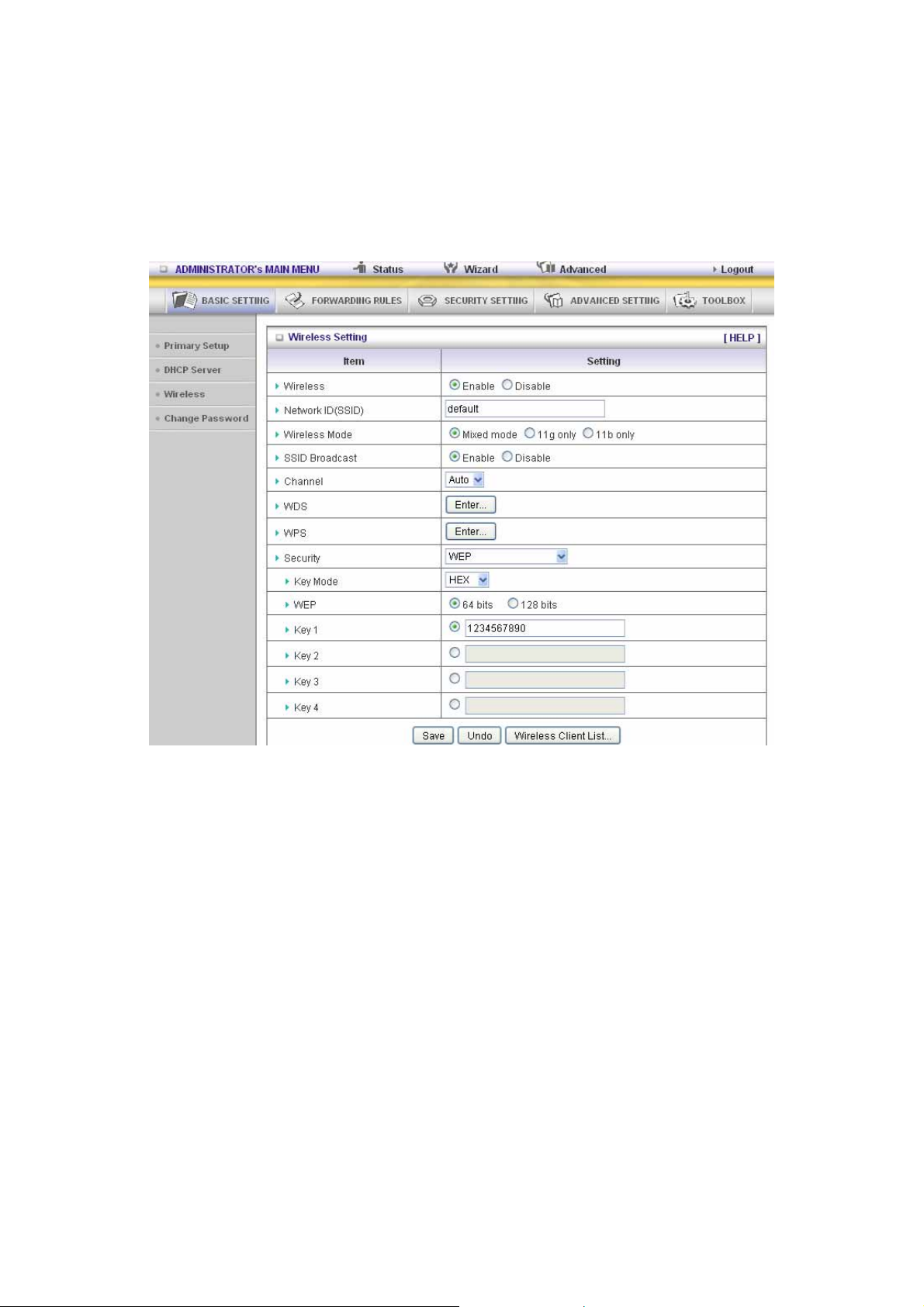
3.3.1.3 Wireless Setting
Wireless settings allow you to set the wireless configuration items.
Wireless : The user can enable or disable wireless function.
Network ID (SSID): Network ID is used for identifying the Wireless LAN (WLAN). Client stations
can roam freely over this product and other Access Points that have the same Network ID. (The
factory setting is “default”)
SSID Broadcast: The router will Broadcast beacons that have some information, including SSID
so that the wireless clients can know how many ap devices by scanning function in the network.
Therefore, this function is disabled, the wireless clients can not find the device from beacons.
Channel: The radio channel number. The permissible channels depend on the Regulatory
Domain.
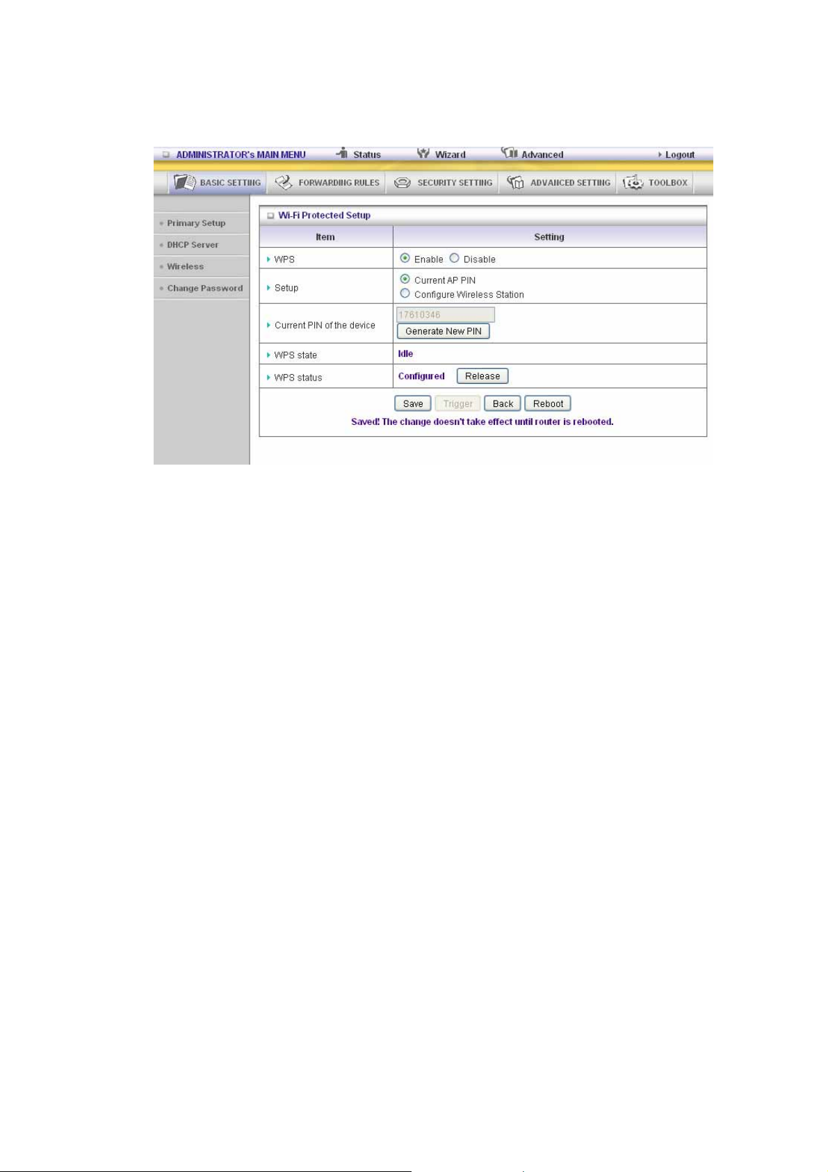
WPS (WiFi Protection Setup)
WPS is WiFi Protection Setup which is similar to WCN-NET and offers safe and easy way in
wireless Connection.
26
Page 27
27
Page 28

WDS(Wireless Distribution System)
WDS operation as defined by the IEEE802.11 standard has been made available. Using WDS it is
possible to wirelessly connect Access Points, and in doing so extend a wired infrastructure to
locations where cabling is not possible or inefficient to implement.
Security: Select the data privacy algorithm you want. Enabling the security can protect your data
while it is transferred from one station to another.
There are several security types to use:
WEP :
When you enable the 128 or 64 bit WEP key security, please select one WEP key to be used and
input 26 or 10 hexadecimal (0, 1, 2…8, 9, A, B…F) digits.
802.1X
Check Box was used to switch the function of the 802.1X. When the 802.1X function is enabled,
the Wireless user must authenticate to this router first to use the Network service.
RADIUS Server
IP address or the 802.1X server’s domain-name.
RADIUS Shared Key
Key value shared by the RADIUS server and this router. This key value is consistent with the key
value in the RADIUS server.
28
Page 29
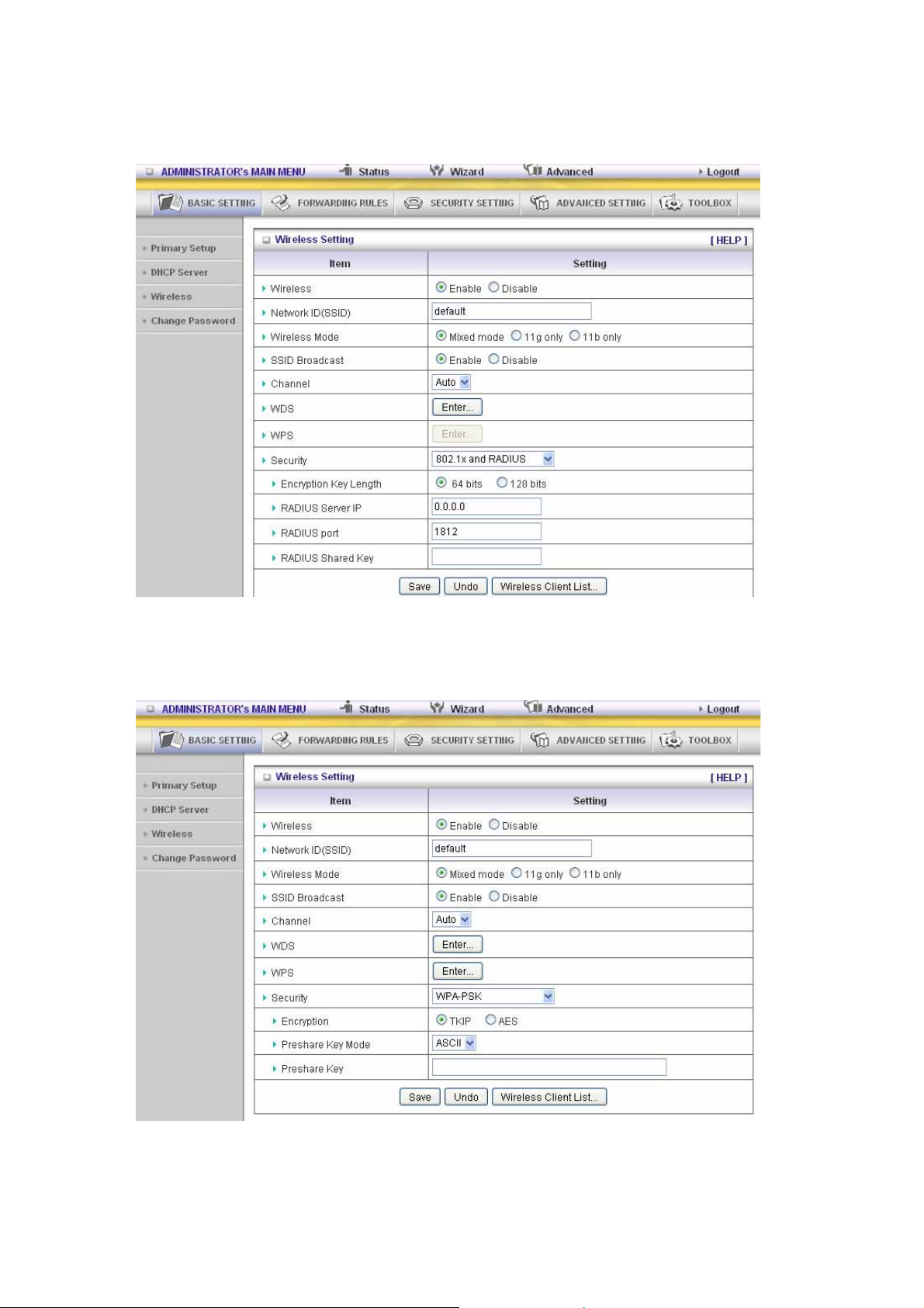
WPA-PSK
1. Select Encryption and Pre-share Key Mode
If you select HEX, you have to fill in 64 hexadecimal (0, 1, 2…8, 9, A, B…F) digits
If ASCII, the length of pre-share key is from 8 to 63.
2. Fill in the key, Ex 12345678
WPA
29
Page 30
Check Box was used to switch the function of the WPA. When the WPA function is enabled, the
Wireless user must authenticate to this router first to use the Network service. RADIUS Server IP
address or the 802.1X server’s domain-name.
Select Encryption and RADIUS Shared Key
If you select HEX, you have to fill in 64 hexadecimal (0, 1, 2…8, 9, A, B…F) digits.
If ASCII, the length of pre-share key is from 8 to 63.
Key value shared by the RADIUS server and this router. This key value is consistent with the key
value in the RADIUS server.
WPA2-PSK(AES)
1. Select Pre-share Key Mode
If you select HEX, you have to fill in 64 hexadecimal (0, 1, 2…8, 9, A, B…F) digits
If ASCII, the length of Pre-share key is from 8 to 63.
2. Fill in the key, Ex 12345678
WPA2(AES)
Check Box was used to switch the function of the WPA. When the WPA function is enabled, the
Wireless user must authenticate to this router first to use the Network service. RADIUS Server
IP address or the 802.1X server’s domain-name.
Select RADIUS Shared Key
If you select HEX, you have to fill in 64 hexadecimal (0, 1, 2…8, 9, A, B…F) digits.
If ASCII, the length of Pre-share key is from 8 to 63.
Key value shared by the RADIUS server and this router. This key value is consistent with the key
value in the RADIUS server .
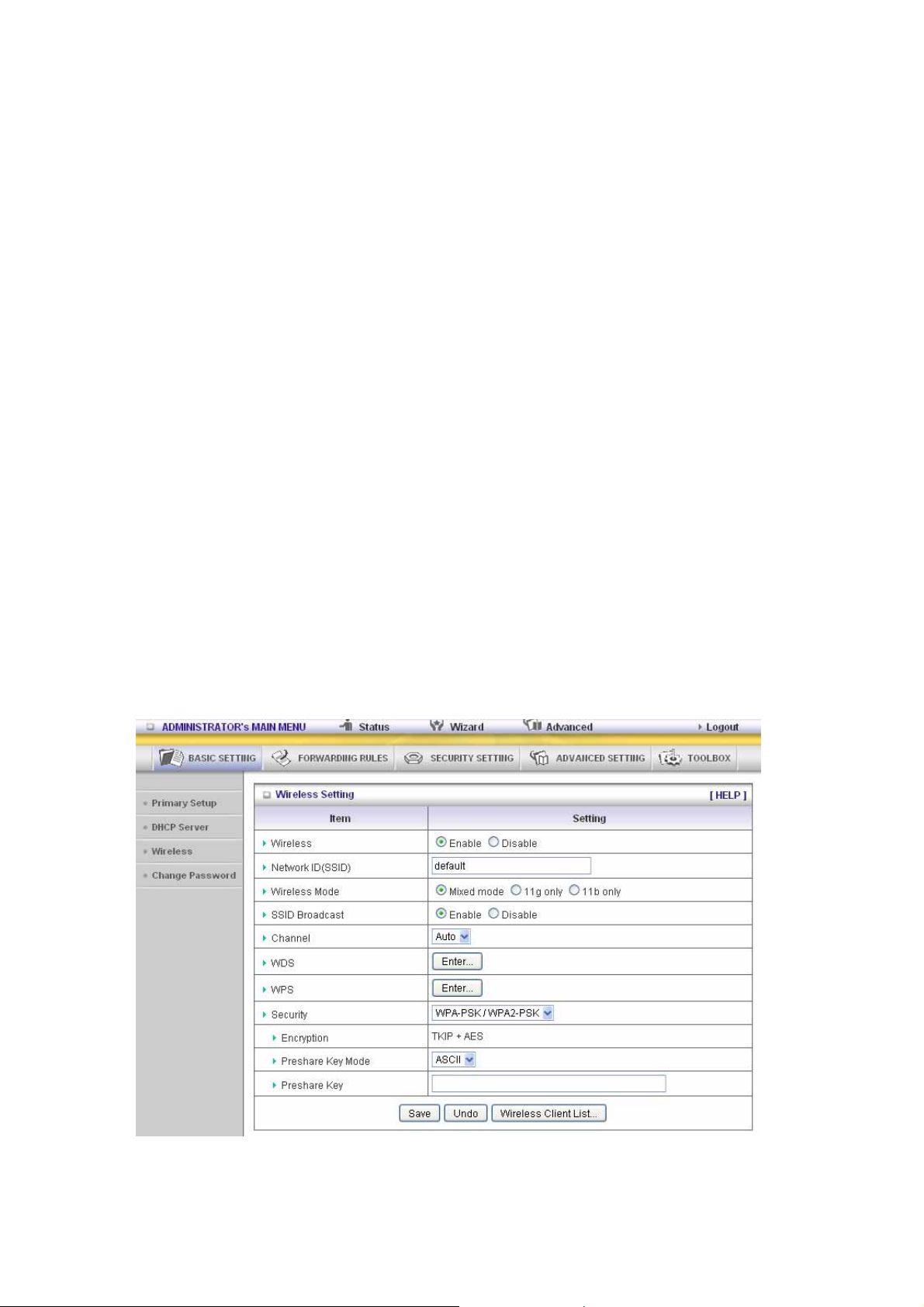
WPA-PSK /WPA2-PSK
The router will detect automatically which Security type the client
uses to encrypt.
1. Select Pre-share Key Mode
If you select HEX, you have to fill in 64 hexadecimal (0, 1, 2…8, 9, A, B…F) digits.
If ASCII, the length of Pre-share key is from 8 to 63.
2. Fill in the key, Ex 12345678
30
Page 31
WPA/WPA2
Check Box was used to switch the function of the WPA. When the WPA function is enabled, the
Wireless user must authenticate to this router first to use the Network service. RADIUS Server
The router will detect automatically which Security type (Wpa-psk version 1 or 2) the client uses to
encrypt.
IP address or the 802.1X server’s domain-name.
Select RADIUS Shared Key
If you select HEX, you have to fill in 64 hexadecimal (0, 1, 2…8, 9, A, B…F) digits
If ASCII, the length of Pre-share key is from 8 to 63.
Key value shared by the RADIUS server and this router. This key value is consistent with the key
value in the RADIUS server.
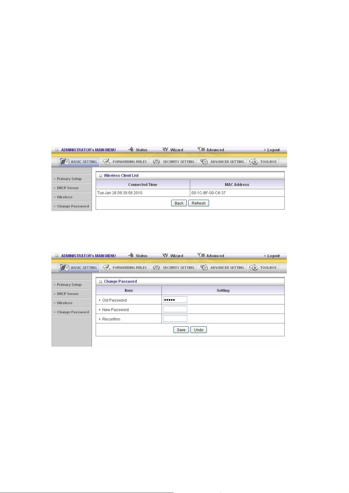
Wireless Client List
3.3.1.4 Change Password
Y ou can change Password here. We strongly reco mmen d you to change th e sys tem p assw ord fo r
security reason.
31
Page 32

3.3.2 Forwarding Rules
32
Page 33

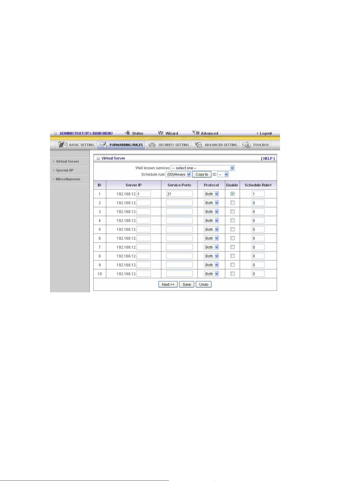
3.3.2.1 Virtual Server
This product’s NAT firewall filters out unrecognized packets to protect your Intranet, so all hosts
behind this product are invisible to the outside world. If you wish, you can make some of them
accessible by enabling the Virtual Server Mapping.
A virtual server is defined as a Service Port, and all requests to this port will be redirected to the
computer specified by the Server IP Virtual Server can work with Scheduling Rules, and give
user more flexibility on Access control. For Detail, please refer to Scheduling Rule.
33
Page 34

3.3.2.2 Special AP
Some applications require multiple connections, like Internet games, Video conferencing, Internet
telephony, etc. Because of the firewall function, these applications cannot work with a pure NAT
router. The S pecial Applications feature allows some of these applications to work with this
product. If the mechanism of Special Applications fails to make an application work, try setting your
computer as the DMZ host instead.
1. Trigger: the outbound port number issued by th e application.
2. Incoming Ports: when the trigger packet is detected, the inbound packets sent to the
specified port numbers are allowed to pass through the firewall.
This product provides some predefined settings Select your app lication and click “Copy to”
to add the predefined setting to your list.
Note! At any given time, only one PC can use each Special Application tunnel.
34
Page 35

3.3.2.3 Miscellaneous Items
IP Address of DMZ Host
DMZ ( Demilitarized Zone) Host is a host without the protection of firewall. It allows a computer to
be exposed to unrestricted 2-way communication for Internet games, Video conferencing, Internet
telephony and other special applications.
NOTE: This feature should be used only when needed.
Non-standard FTP port
You have to configure this item if you want to access an FTP server whose port number is not 21.
This setting will be lost after rebooting.
Xbox Support
The Xbox is a video game console produced by Microsoft Corporation. Please enable this function
when you play games.
UpnP Setting
The device also supports this function. If the OS supports this function enable it, like Windows XP.
When the user get IP from Device and will see icon as below:
35
Page 36

3.3.3 Security Settings
36
Page 37

3.3.3.1 Packet Filters
Packet Filter enables you to control what packets are allowed to pass the router. Outbound filter
applies on all outbound packets. However, Inbound filter applies on packets that destined to Virtual
Servers or DMZ host only. You can select one of the two filtering policies:
1. Allow all to pass except those match the specified rules
2. Deny all to pass except those match the specified rules
You can specify 8 rules for each direction: inbound or outbound. For each rule, you can define the
following:
• Source IP address
• Source port address
• Destination IP address
• Destination port address
• Protocol: TCP or UDP or both.
• Use Rule#
For source or destination IP address, you can define a single IP address (4.3.2.1) or a range of IP
addresses (4.3.2.1-4.3.2.254). An empty implies all IP addresses.
For source or destination port, you can define a single port (80) or a range of ports (1000-1999).
Add prefix "T" or "U" to specify TCP or UDP protoc ol. Fo r exam ple, T80, U53, U2000-2 999. No
prefix indicates both TCP and UDP are defined. An empty implies all port addresses. Packet Filter
can work with Scheduling Rules, and give user more flexibility on Access control. For Detail,
please refer to Scheduling Rule.
37
Page 38

Each rule can be enabled or disabled individually.
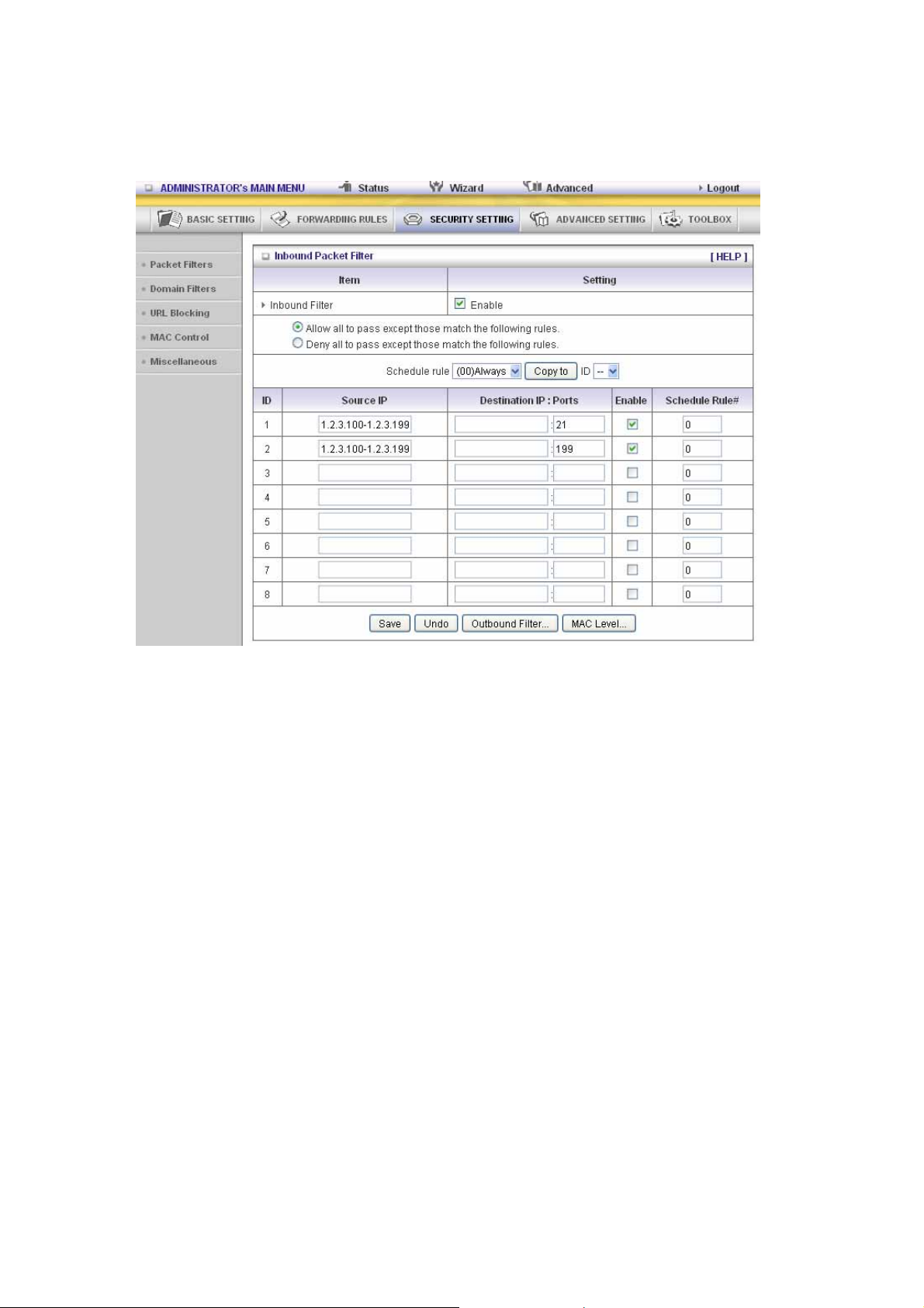
Inbound Filter:
To enable Inbound Packet Filter click the check box next to Enable in the Inbound Packet Filter
field.
Suppose you have SMTP Server (25), POP Server (110), Web Server (80), FTP Server (21), and
News Server (119) defined in Virtual Server or DMZ Host.
Example 1:
(1.2.3.100-1.2.3.149) Remote hosts are allow to send mail (port 25), and browse the Internet (port
80)
(1.2.3.10-1.2.3.20) Remote hos ts can do everything (block nothing)
Others are all blocked.
38
Page 39
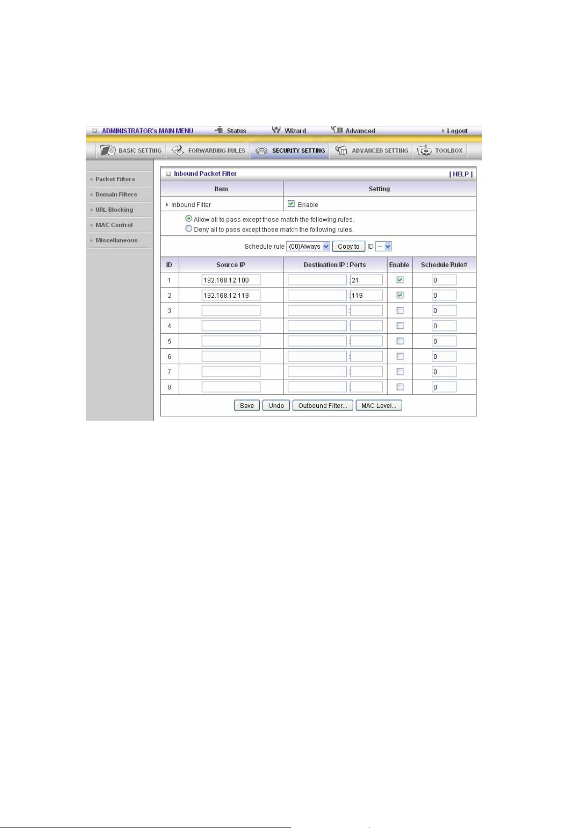
Example 2:
(1.2.3.100-1.2.3.119) Remote hosts can do everything except read net news (port 119) and
transfer files via FTP (port 21) behind Router Server.
Others are all allowed.
After Inbound Packet Filter setting is configured, click the save button.
39
Page 40

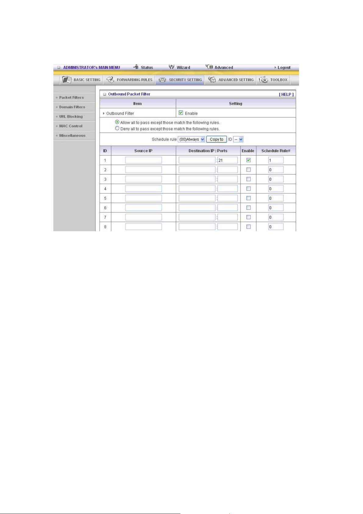
Outbound Filter:
To enable Outbound Packet Filter click the check box next to Enable in the Outbound Packet
Filter field.
Example 1:
Router LAN IP is 192.168.12.254
(192.168.12.100-192.168.12.149) Located hosts are only allowed to send mail (port 25), receive
mail (port 110), and browse Internet (port 80); port 53 (DNS) is necessary to resolve the domain
name.
(192.168.12.10-192.168.12.20) Located hosts can do everything (block nothing)
Others are all blocked.
40
Page 41
Example 2:
Router LAN IP is 192.168.12.254
(192.168.12.100 and 192.168.12.119) Located Hosts can do everything except read net news
(port 119) and transfer files via FTP (port 21)
Others are allowed
After Outbound Packet Filter setting is configured, click the save button.
41
Page 42

3.3.3.2 Domain filters
Domain Filter
Let you prevent users under this device from accessing specific URLs.
Domain Filter Enable
Check if you want to enable Domain Filter.
Log DNS Query
Check if you want to log the action when s ome one a ccesses the specific URLs.
Privilege IP Addresses Ra ng e
Setting a group of hosts and privilege these hosts to access network without restriction.
Domain Suffix
A suffix of URL to be restricted. For example, ".com", "xxx.com".
Action
When someone is accessing the URL met the domain-suffix, what kind of action you want.
Check drop to block the access. Check log to log this access.
Enable
Check to enable each rule.
Example:
42
Page 43

In this example:
1. URL include “www.msn.com” will be blocked, and the action will be record in log-file.
2. URL include “www.sina.com” will not be blocked, but the action will be record in log-file.
3. URL include “www.baidu.com” will be blocked, but the action will not be record in log-file.
4. IP address x.x.x.1~x.x.x.99 can access Internet without restriction.
43
Page 44

3.3.3.3 URL Blocking
URL Blocking will block LAN computers to connect to pre-defined Websites.
The major difference between “Domain filter” and “URL Blocking” is Domain filter require user to
input suffix (like .com or .org, etc), while URL Blocking require user to input a keyword only. In
other words, Domain filter can block specific website, while URL Blocking can block hundreds of
websites by simply a keyword.
URL Blocking Enable
Checked if you want to enable URL Blocking.
URL
If any part of the Website's URL matches the pre-defined word, the connection will be blocked. For
example, you can use pre-defined word "sex" to block all websites if their URLs contain
pre-defined word "sex".
Enable
Checked to enable each rule.
44
Page 45

In this example:
1. URL include “msn” will be blocked, and the action will be record in log-file.
2. URL include “sina” will be blocked, but the action will be record in log-file
45
Page 46

3.3.3.4 MAC control
MAC Address Control allows you to assign different access right for different users and to assign a
specific IP address to a certain MAC address.
MAC Address Control Check “Enable” to enable the “MAC Address Control”. All of the settings
in this page will take effect only when “Enable” is checked.
Connection control Check "Connection control" to enable the controlling of which wired and
wireless clients can connect to this device. If a client is denied to
connect to this device, it means the client can't access to the Internet
either. Cho ose "allow" or "deny" to allow or deny the client s, whose
MAC addresses are not in the "Control table" (please see below), to
connect to this device.
Association control Check "Association control" to enable the controlling of which wireless
client can associate to the wireless LAN. If a client is denied to
associate to the wireless LAN , it mean s the client can't s end or receiv e
any data via this device. Choose "allow" or "deny" to allow or deny the
clients, whose MAC addresses are not in the "Control table", to
associate to the wireless LAN.
Control table
46
Page 47

"Control table" is the table at the bottom of the "MAC Address Control" page. Each row of this
table indicates the MA C ad dress and the exp ected I P add ress mapp ing of a clien t. Th ere are
four columns in this table:
MAC Addres s
IP Address
C When "Connection control" is checked,
A When "Association control" is checked,
MAC address indicates a specific client.
Expected IP address of the corresponding
client. Keep it empty if you don't care its IP
address.
check "C" will allow the corresponding client
to connect to this device.
check "A" will allow the corresponding client
to associate to the wireless LAN.
In this page, we provide the following Combobox and button to help you to input the MAC
address.
You can select a specific client in the “DHCP clients” Combobox, and then click on the “Copy
to” button to copy the MAC address of the client you select to the ID selected in the “ID”
Combobox.
Previous page and Next Page To make this setup page simple and clear, we have divided
the “Control table” into several pages. You can use these
buttons to navigate to different pages.
47
Page 48
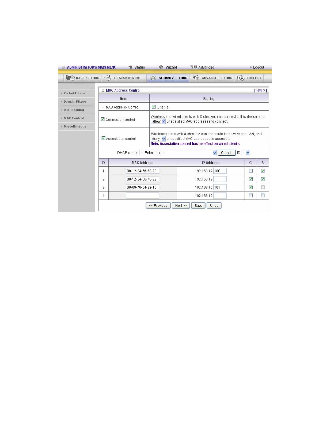
Example:
In this scenario, there are three clients listed in the Control Table. Clients 1 and 2 are
wireless, and client 3 is wired.
1. The "MAC Address Control" function is enabled.
2. "Connection control" is enabled, and all of the wired and wireless clients not listed in the
"Control table" are "allowed" to connect to this device.
3. "Association control" is enabled, and all of the wireless clients not listed in the "Control
table" are "denied" to associate to the wireless LAN.
4. Clients 1 and 3 have fixed IP addresses either from the DHCP server of this device or
manually assigned:
ID 1 - "00-12-34-56-78-90" --> 192.168.12.100
ID 3 - "00-98-76-54-32-10" --> 192.168.12.101
Client 2 will obtain its IP address from the IP Address pool specified in the "DHCP
Server" page or can use a manually assigned static IP address.
If, for example, client 3 tries to use an IP address different from the address listed in the
Control table (192.168.12.101), it will be denied to connect to this device.
5. Clients 2 and 3 and other wired clients with a MAC address unspecified in the Control
table are all allowed to connect to this device. But client 1 is denied to connect to this
device.
6. Clients 1 and 2 are allowed to associate to the wireless LAN, but a wireless client with a
MAC address not specified in the Control table is denied to associate to the wireless
LAN. Client 3 is a wired client and so is not affected by Association control.
48
Page 49

3.3.3.5 MiscelLANeous Items
Remote Administrator Host/Port
In general, only Intranet user can browse the built-in web pages to perform administration task.
This feature enables you t o pe rform adm inis tra tion t as k from remo te host . If this feat ure is ena bled,
only the specified IP address can perform remote administration. If the specified IP address is
0.0.0.0, any host can connect to this product to perform administration task. You can use subnet
mask bits "/nn" notation to specified a group of trusted IP addresses. For example, "10.1.2.0/24".
NOTE: When Remote Administration is enabled, the web server port will be shifted to 88. You can
change web server port to other port, too.
Administrator Time-out
The time of no activity to logout automatically. Set it to zero to disable this feature.
Discard PING from WAN side
When this feature is enabled, any host on the WAN cannot ping this product.
SPI Mode
When this feature is enabled, the router will record the packet information pass through the router
like IP address, port address, ACK, SEQ number and so on. And the router will check every
incoming packet to detect if this packet is valid.
DoS Attack Detection
When this feature is enabled, the rou ter will detect and log the DoS attack comes from the Internet.
Currently, the router can detect the following DoS attack: SYN Attack, WinNuke, Port Scan, Ping of
Death, LANd Attack etc.
VPN PPTP and IPSec Pass-Through
Virtual Private Networking (VPN) is typically used for work-related networking. For VPN tunnels,
the router supports IPSec Passthrough and PPTP Passthrough.
49
Page 50

3.3.4 Advanced Settings
50
Page 51

3.3.4.1 System Time
Get Date and Time by NTP Protocol
Selected if you want to Get Date and Time by NTP Protocol.
Time Server
Select a NTP time server to consult UTC time
Time Zone
Select a time zone where this device locates.
Set Date and Time manually
Selected if you want to Set Date and Time manually.
Set Date and Time manually
Selected if you want to Set Date and Time manually.
Function of Buttons
Sync Now: Synchronize system time with network time server
Daylight Saving:Set up where the location is.
51
Page 52

3.3.4.2 System Log
This page support two methods to export system logs to specific destination by means of
syslog(UDP) and SMTP(TCP). The items you have to setup including:
IP Address for Syslog
Host IP of destination where syslogs will be sent to.
Check Enable to enable this function.
E-mail Alert Enable
Check if you want to enable Email alert (send s ys lo g vi a ema il).
SMTP Server IP and Port
Input the SMTP server IP and port, which are concated with ':'. If you do not specify port number,
the default value is 25.
For example, "mail.your_url.com" or "192.168.1.100:26".
Send E-mail alert to
The recipients who will receive these logs. You can assign more than 1 recipient, using ';' or ',' to
separate these email addresses.
52
Page 53
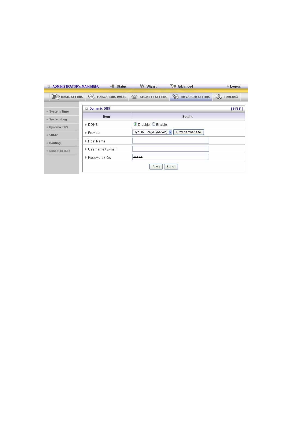
3.3.4.3 System Log
To host your server on a changing IP address, you have to use dynamic domain name service
(DDNS).
So that anyone wishing to reach your host only needs to know the name of it. Dynamic DNS will
map the name of your host to your current IP address, which changes each time you connect your
Internet service provider.
Before you enable Dynamic DNS, you need to register an account on one of these Dynamic DNS
servers that we list in provider field.
To enable Dynamic DNS click the check box next to Enable in the DDNS field.
Next you can enter the appropriate information about your Dynamic DNS Server.
You have to define:
Provider
Host Name
Username/E-mail
Password/Key
You will get this information when you register an account on a Dynamic DNS server.
53
Page 54

3.3.4.4 SNMP
In brief, SNMP, the Simple Network Management Protocol, is a protocol designed to give a user
the capability to remotely manage a computer network by polling and setting terminal values and
monitoring network e vents.
Enable SNMP
You must check Local, Remote or both to enable SNMP function. If Local is checked, this device
will response request from LAN. If Remote is checked, this device will response request from
WAN.
Get Community
Setting the community of GetRequest your device will response.
Set Community
Setting the community of SetRequest your device will accept.
IP 1, IP 2, IP 3, IP 4
Input your SNMP Management PC’s IP here. User has to configure to where this device should
send SNMP Trap message.
SNMP Version
Please select proper SNMP Version that your SNMP Management software supports.
WAN Access IP Address
If the user wants to limit to specific the IP address to a ccess, please input in the item. The default
0.0.0.0 and means every IP of Internet can get some information of device with SNMP protocol.
Click on “Save” to store your setting or “Undo” to give up.
54
Page 55

3.3.4.5 Routing
Routing T a bles allow you to determine which physical interface address to use for outgoing IP
data grams. If you have more than one routers and subnets, you will need to enable routing table
to allow packets to find proper routing path and allow different subnets to communicate with each
other.
Routing Table settings are settings used to setup the functions of static.
Dynamic Routing
Routing Information Protocol (RIP) will exchange information about destinations for computing
routes throughout the network. Please select RIPv2 only if you have different subnet in your
network.
Otherwise, please select RIPv1 if you need this protocol.
Static Routing: For static routing, you can specify up to 8 routing rules. You can enter the
destination IP address, subnet mask, gateway, hop for each routing rule, and then enable or
disable the rule by ch ecking or unchecking the Enable checkbox.
Example:
55
Page 56

Configuration on NAT Router
Destination SubnetMask Gateway Hop Enabled
192.168.1.0 255.255.255.0 192.168.123.216 1 ˇ
192.168.0.0 255.255.255.0 192.168.123.103 1 ˇ
So if, for example, the client 3 wanted to send an IP data gram to 192.168.0.2, it would use the
above table to determine that it had to go via 192.168.123.103 (a gateway),
And if it sends Packets to 192.168. 1.11 will go via 192.168.12 3. 216
Each rule can be enabled or disabled individually.
After routing table setting is configured, click the save button.
56
Page 57

3.3.4.6 Schedule Rule
You can set the schedule time to decide which service will be turned on or off. Select the “enable”
item.
Press “Add New Rule”
You can write a rule name and set which day and what time to schedule from “Start Time” to
“End Time”. The following example configure “ftp time” as everyday 14:10 to 16:20
57
Page 58
Schedule Enable
Selected if you want to Enable the Scheduler.
Edit
To edit the schedule rule.
Delete
To delete the schedule rule, and the rule# of the rules behind the deleted one will decrease one
automatically.
Schedule Rule can be apply to Virtual server and Packet Filter, for example:
Exanple1: Virtual Server – Apply Rule#1 (ftp time: everyday 14:20 to 16:30)
Exanple2: Packet Filter – Apply Rule#1 (ftp time: everyday 14:20 to 16:30).
58
Page 59
59
Page 60

3.3.4.7 QoS Rule
Local IP:
Please input Client IP,ex192.168.12.33.
Remote Priority:
Please input Global IP and port,ex:168.96.2.3 and port 21
60
Page 61

3.3.5 Toolbox
61
Page 62
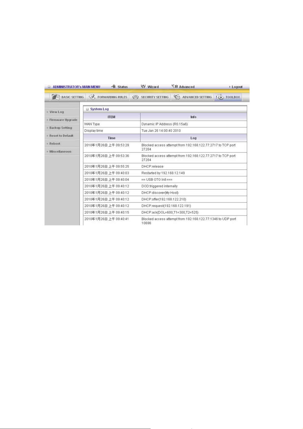
3.3.5.1 View Log
can View system log by clicking the View Log button
You
62
Page 63
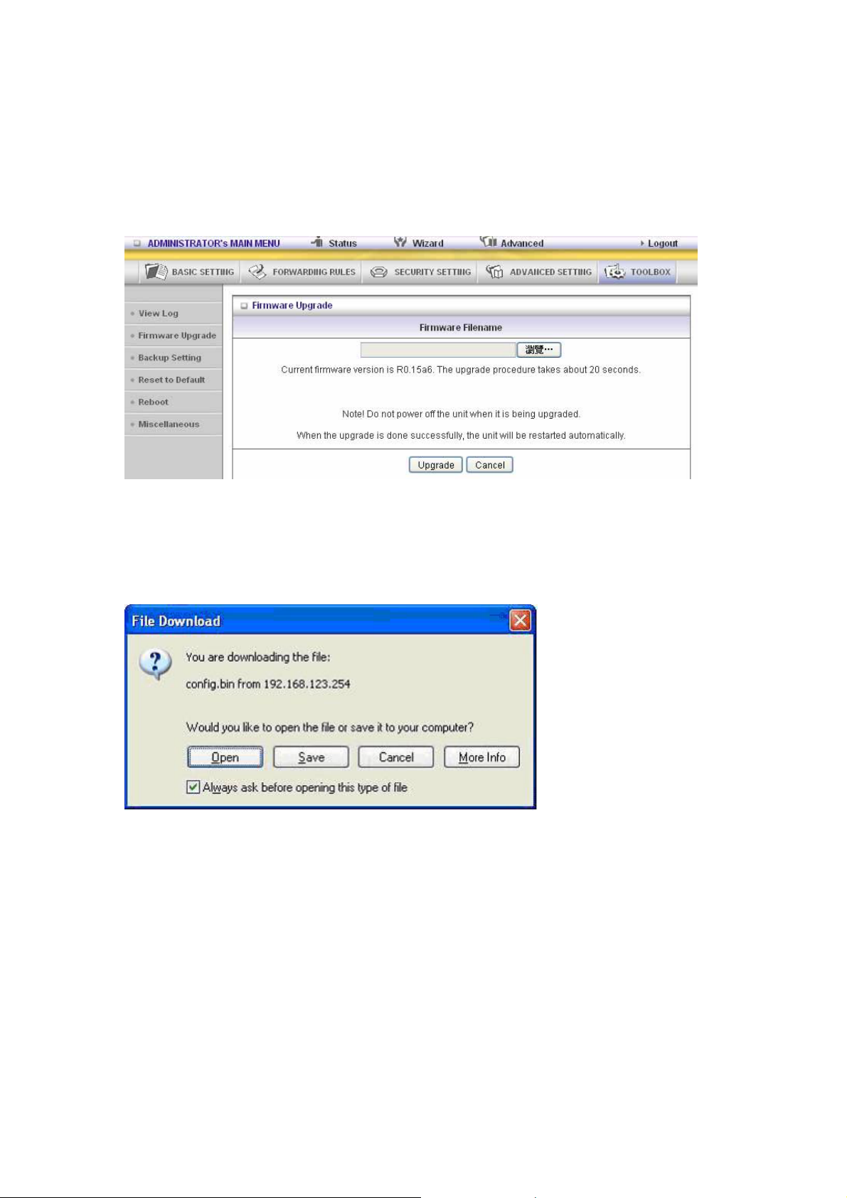
3.3.5.2 Firmware Upgrade
You can upgrade firmware by clicking Firmware Upgrade button.
3.3.5.3 Backup Setting
Y ou can backup your settings by clicking the Backup Setting button and save it as a bin file. Once
you want to restore these settings, please click Firmware Upgrade button and use the bin file you
saved.
63
Page 64

3.3.5.4 Reset to default
You can also reset this product to factory default by clicking the Reset to default button.
3.3.5.5 Reboot
You can also reboot this product by clicking the Reboot button.
3.3.5.6 MiscelLANeous Items
MAC Address for Wake-on-LAN
Wake-on-LAN is a technology that en able s yo u to pow e r up a ne tw o rk ed device remotely. In order
to enjoy this feature, the target device must be Wake-on-LAN enabled and you have to know the
MAC address of this device, say 00-1 1- 22-33 -4 4- 55. Clicking "Wake up" button will make the
64
Page 65

router to send the wake-up frame to the target device immediately.
Domain Name or IP Address for Test
Allow you to configure an IP, and ping the device. You can ping a secific IP to test whether it is
alive.
65
Page 66

CHAPTER 4. Troubleshooting
This Chapter provides solutions to problems for the installation and operation of the WiFi ADSL
Router. You can refer to the following if you are having problems.
1 Why can’t I configure the router even the cable is
plugged and the LED is lit?
Do a Ping test to make sure that the WiFi Combo Note: It is recommended that you use
VPN Router is responding.
Go to Start > Run.
1. Type cmd.
2. Press OK.
3. Type ipconfig to get the IP of default gateway.
4. Type “ping 192.168.123.254”. Assure that you ping the correct IP Address assigned to
the WiFi ADSL Router. It will show four replies if you ping correctly.
an Ethernet connection to configure it.
Ensure that your Ethernet Adapter is working, and that all network drivers are installed
properly. Network adapter names will vary depending on your specific adapter. The
installation steps listed below are applicable for all network adapters.
1. Go to Start > Right click on “My Computer” > Properties.
2. Select the Hardware Tab.
3. Click Device Manage r.
4. Double-click on “Network Adapters”.
5. Right-click on Wireless Card bus Adapter or your spec ific ne twork adapter.
66
Page 67

6. Select Properties to ensure that all drivers are installed properly.
7. Look under Device Status to see if the device is working properly.
8. Click “OK”.
2 What can I do if my Ethernet connection does not
work properly?
A. Make sure the RJ45 cable connects with the route r.
B. Ensure that the setting on your Network Interface Card adapter is “Enabled”.
C. If settings are correct, ensur e that you are not using a crossover Ethernet cable, not all
Network Interface Cards are MDI/MDIX compatible, and use a patch cable is
recommended.
D. If the connection still doesn’t work properly, then you can reset it to default.
3 Problems with 3G connection? ( only for the model with
3G support function)
A. What can I do if the 3G connection is failed by Auto detection?
Maybe the device can’t recognize your ISP automatically. Please select “Manual” mode,
and filling in dial-up settings manually.
B. What can I do if my country and ISP are not in the list?
Please choose “Others” item from the list, and filling in dial-up settings manually.
C. What can I do if my 3G connection is failed even the dongle is plugged?
Please check the following items:
I. Make sure you have inserted a validated SIM card in the 3 G data card, and the
subscription from ISP is still available
II. If you activate PIN code check feature in SIM card, m aking sure the PI N co de you
fill in dial-up page is correct
III. Checki ng with your ISP to see all dial-up settings are correct
IV. Make sure 3G signal from your ISP is available in your environment
D. What can I do if my router can’t recognize my 3G data card even it is
plugged?
There might be compatibility issue with some certain 3G cards. Please check the latest
compatibility list to see if your 3G card is already supported.
E. What should I insert in APN, PIN Code, Account, Password, Primary DNS,
and Secondary DNS?
The device will show this information after you choose country and Telcom. You can
also check these values with your ISP.
F. Which 3G network should I select?
It depends on what service your ISP provider. Please check your ISP to know this
67
Page 68

information.
G. Why does my 3G connection keep dropping?
Please check 3G signal strength from your ISP in your environment is above middle
level.
4 Something wrong with the wireless connection?
A. Ca n’t setup a wireless connection?
I. Ensure that the SSID and the encryption settings are exactly the same to the
Clients.
II. Move the WiFi ADSL Router and the wireless client into the same room, and then
test the wireless connection.
III. Disable all security settings such as WEP, and MAC Address Control.
IV. Turn off the WiFi ADSL Router and the client, then re start it and then turn on the
client again.
V. Ensure that the LEDs are indicating normally. If not, make sure that the power and
Ethernet cables are firmly connected.
VI. Ensure that the IP Address, subnet mask, gateway and DNS settings are correctly
entered for the network.
VII. If you are using other wireless device, home security systems or ceiling fans,
lights in your home, your wireless connection may degrade dramatically. Keep
your product away from electrical devices that generate RF noise such as
microwaves, monitors, electric motors…
B. What can I do if my wireless client can not access the Internet?
I. Out of range: Put the router closer to your client.
II. Wrong SSID or Encryption Key: Check the SSID or Encryption setting.
III. Connect with wrong AP: Ensure that the client is connected with the correct
Access Point.
i. Right-click on the Local Area Connection icon in the taskbar.
ii. Select View Available Wireless Networ ks in Wirele ss Configur e. Ensure you
have selected the correct available network.
iii. Reset the WiFi ADSL Router to default setting
C. Why does my wireless connection keep dropping?
I. Antenna Orientation.
i. Try different antenna orientations for the WiFi ADSL Router.
ii. Try to keep the antenna at least 6 inches away from the wall or other objects.
II. Try changing the channel on the WiFi ADSL Router, and your Access Point a nd
Wireless adapter to a different channel to avoid interference.
68
Page 69

III. Keep your product away from electrical devices that generate RF noise, like
microwaves, monitors, electric motors, etc.
5 What to do if I forgot my encryption key?
1. Go back to advanced setting to set up your Encryption key again.
2. Reset the WiFi ADSL Router to default setting
69
Page 70

Appendix A. Spec Summary Table
Device Interface CDD530AM-002
ADSL Line xDSL port (Annex A) 1
Ethernet LAN RJ-45 port, 10/100Mbps, auto-MDI/MDIX 4
1-port ADSL2+ connector
ADSL2 /2+
Standard Module
Antenna For 1.8 dBm detachable antenna 1
WPS Button WPS Button 1
Wireless On/Off
Button
LED Indication
Power Jack
Wireless LAN (WiFi)
Standard IEEE 802.11b/g/n-lite(1T1R) compliance
SSID SSID broadcast or in stealth mode
Channel Auto-selection, manually
Security WEP, WPA, WPA-PSK, WPA2, WPA2-PSK
WPS WPS (Wi-Fi Protected Setup)
WMM WMM (Wi-Fi Multimedia)
ITU 992.1 (G.dmt) Annex A, ITU 992.2
(G.lite), ITU 992.3 ADSL2 (G.dmt.bis), ITU
992.5 ADSL2+
Enable /Disable Wireless On/Off 1
ADSL/Status / LAN1 ~ LAN4/ WiFi
DC Power Jack, powered via external DC
9V/1A switching power adapter
●
●
1
●
●
●
●
●
●
Functionality
DSL WAN PPPoE / PPPoA / IPoA / Static IP / Dynamic IP
WAN Connection Auto-reconnect, dial-on-demand, manually
Virtual server, special application, DMZ, Super
One-to-Many NAT
NAT Session Support NAT session 8000
SPI Firewall IP/Service filter, URL blocking, MAC control
DoS Protection DoS (Deny of Service) detection and protection
Routing Protocol Static route, dynamic route (RIP v1/v2)
Management SNMP, UPnP IGD, syslog
Administration
Environment & Certification
Package
Information
Operation Temp.
DMZ (IP pass through) And IPTV IGMP V1 V2
Pass through
Web-based UI, remote login, backup/restore
setting
Package dimension (mm)
Package weight (g)
Temp.: 0~40oC, Humidity 10%~90%
non-condensing
●
●
●
●
●
●
●
●
●
70
Page 71

Storage Temp.
Temp.: -10~70oC, Humidity: 0~95%
non-condensing
EMI Certification CE/FCC compliance
RoHS RoHS compliance
*Specifications are subject to change without notice.
●
●
●
71
Page 72

Page 73

 Loading...