

Page 1
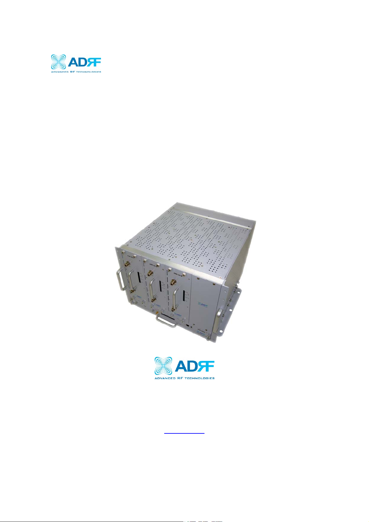
SDR Modular Repeater
SER MANUAL
U
Version 0.4
3116 West Vanowen St.
Burbank, CA 91505
Tel: 818-840-8131
Fax: 818-840-8138
www.adrftech.com
Page 2

User Manual V0.4
SDR Repeater
Glossary
The following is a list of abbreviations and terms used throughout this document.
Abbreviation/Term Definition
AGC Automatic Gain Control
ALC Automatic Level Control
AROMS ADRF’ Repeater Operation and Management
System
BTS Base Transceiver Station
CDMA Code Division Multiple Access
CFE Compact Front End
CW Continuous Wave (un-modulated signal)
DAS Distributed Antenna System
DL Downlink
Downlink The path covered from the Base Transceiver
Station (BTS) to the subscribers service area via
the repeater
HPA High Power Amplifier
HW Hardware
IF Intermediate Frequency
LNA
LTE
Low Noise Amplifier
Long Term Evolution
MS Mobile Station
PLL Phased Locked Loop
PS Power Supply
RF Radio Frequency
SQE Signal Quality Estimate
SW Software
UL Uplink
Uplink The path covered from the subscribers service
area to the Base Transceiver Station(BTS) via the
repeater
VSWR Voltage Standing Wave Ratio
Page | 2
Page 3
SDR Repeater
User Manual V0.4
Released version: 0.4
Information in this document is subject to change without notice.
Advanced RF Technologies, Inc. 1996-2011.
All rights reserved.
Please send comments to:
E-Mail: info@adrftech.com
Phone: (818) 840-8131
(800) 313-9345
Fax: (818) 840-8138
Address: Advanced RF Technologies, Inc.
Attention: Technical Publications Department
3116 Vanowen St.
Burbank, CA 91505
USA
www.adrftech.com
Revision History
Version Author Description Date
0.1 Sun Kim Initial Release January 18, 2011
0.2 Sun Kim Revised max gain levels for SMR module May 10, 2011
0.3 Sun Kim Revised Band Selection section on the Install Page July 15, 2011
0.4 Sun Kim Update illustrations and changes to specifications;
July 19, 2011
added Closeout Package, User Log, and Backup
sections
Page | 3
Page 4

User Manual V0.4
TAB LE OF CONTE NTS
SDR Repeater
1. SDR REPEATER..............................................................................................................6
1.1 Introduction..................................................................................................................6
1.1.1 Highlights ............................... ...... .. ...... ..... ... ..... ..... ... ..... ...... .. ...... ..... ... ..... ..... ... ...6
1.1.2 Parts List....................................................... ................................ .. ......................7
1.1.3 Repeater Quick View.................................... ..... ..... ... ..... ...... .. ...... ..... ... ..... ..... ......1
2. WARNINGS AND HAZARDS.......................... ........... ............. .............. ............. ...........9
3. SDR OVERVIEW...........................................................................................................11
3.1 Switches & Fault Indicators.......................................................................................11
3.1.1 NMS and Module LED.............................................. ..... ... ..... ...... .. ...... ..... ... ..... .11
3.1.2 Module LEDs......................................................................................................11
3.1.3 Message Board Alarms and Notificati on.............................................. .. ............12
3.2 Switches and Ports.....................................................................................................13
3.2.1 Power Switch............................................. ................................ .........................13
3.2.2 Back Up Battery Switch & Battery Port....................................... ......................13
3.2.3 Ethernet Port and Host/Remote Switch............................................. .................14
3.2.4 RF Ports........ .. ...... ..... ... ..... ..... ... ..... ...... ..... ... ..... ..... ... ..... ...... .. ...... ..... ... ..... ..... ... .14
3.5 Installation..................................................................................................................15
3.5.1 Wall Mount Procedure.................................................... ........... ........... .......... ....15
3.5.2 Rack Mount Procedure.............. ... ..... ..... ... ..... ...... .. ...... ..... ... ..... ..... ... ..... ...... .. ....15
3.5.3 Grounding ...........................................................................................................1
3.5.4 Antenna Separation/Isolation.......................................... ................................ ....17
3.5.5 Line of Sight......... ................................ .. ................................ ... .........................18
4. SDR WEB-GUI SETUP.................................................................................................19
4.1 Repeater/PC Connection Using Web-GUI.................................................................19
4.2 Status Tab...................................................................................................................20
4.2.1 Status- NMS............................................... ... ................................ .. ....................20
4.2.2 Status- SMR, PCS, BRS.....................................................................................22
4.3 Control Tab............................. ... ................................ ... ................................ .. ............25
4.3.1 Control- NMS....................................................... ..... ..... ...... .. ...... ..... ... ..... ..... ... .25
4.3.2 Control- SMR, PCS, BRS...................................................................................26
4.4 Install Tab...................................................................................................................29
4.4.1 Install- NMS................................................................................... ... .................29
4.4.2 Install- SMR.................................................... ... ................................ ... ..............31
4.4.3 Install- PCS............................. ................................ ... ................................ ... ......33
4.4.4 Install- BRS .................................... ................................ ... ................................ .35
4.5 System........................................................................................................................36
4.5.1 System- Account.................................................................................................37
4.5.2 System- Closeout Package................................. ................................ ... ..............38
4.5.3 System- User Log................................. ................................ .. ............................39
4.5.4 System: Update.......................................................................................... .........39
4.5.5 System- Backup...................................... ... ................................ ... ......................39
Page | 4
Page 5

User Manual V0.4
SDR Repeater
4.6 Help.............................................. ................................ .. ................................ ... .........40
4.7 Logout........................................................................................................................40
Clicking the Logout button will log the current user off the system. ..............................40
5. MAINTENANCE GUIDE FOR SDR REPEATER ....................................................41
5.1 Periodic Inspection Checklist......................................................... ............................41
5.2 Preventive Measures for Optimal Operation..............................................................41
5.2.1 Recommendations.............. ..... ...... .. ...... ..... ... ..... ..... ... ..... ...... .. ...... ..... ..... ... ..... ....41
5.2.2 Precautions......................................................... .................................................41
6. WARRANTY AND REP AI R POLICY................................................ ............. ............42
6.1 General Warranty ................................................... ... ................................ ... ..............42
6.2 Limitations of Warranty.............................................................................................42
6.3 Limitation of Damages...............................................................................................42
6.4 No Consequential Damages.............................................. ... ................................ .. ....42
6.5 Additional Limitation on Warranty.............................................................. ..............42
6.6 Return Material Authorization (RMA)...................................................................... .42
7. SPECIFICATIONS........................................................................................................43
7.1 Electrical Specifications.............................................................................................43
7.2 Mechanical Specifications.........................................................................................43
7.3 Power Specifications..................................................................................................44
7.4 Environment Specifications.......................................................................................44
7.5 Warranty & Certificates .................................... ........... .......... ........ ........... ........... ......44
APPENDIX A: MECHANICAL DRAWING............................................... ... .................46
APPENDIX B: SHUTDOWN RETRY LOGIC................................. ..............................47
Page | 5
Page 6

SDR Repeater
User Manual V0.4
1. SDR Repeater
1.1 Introduction
Four technologies in one body: SDR is an over-the-air repeater system that can incorporate up to four (4) technologies
in one body. Current supported technologies are SMR800, SMR900, PCS, and BRS.
1.1.1 Highlights
• Supports up to 4 frequency bands simultaneously
o Covers the SMR800, SMR900, PCS, and BRS, LTE, Cellular, AWS bands
[SDR-S]SMR800- Covers 18 MHz
SMR900- Covers 5 MHz
[SDR-P]PCS- Covers 65 MHz
3 independent RF PCS channels, each channel supports 1.25 to 18.75 MHz
bandwidth
[SDR-B] BRS- Covers 30 MHz
[SDR-700]LTE- Covers A+B:12MHz , C:11MHz
[SDR-C]Cellular- Covers 25MHz
[SDR-A] AWS- Cover 45MHz
• Composite Output Power of 24 or 30 dBm
• 30 dB AGC Range @ 0.5 dB Step
• Adjustable AGC Output Power Level
• Adjustable ALC Level
• Band Selectable via Web-GUI
• Can Support up to 3 Non-Contiguous Bands on the PCS module
• Supports Network Management Monitoring System via SNMP
• Adjustable FA (3 channels)
• Digital filtering
• Incremental Automatic Shutdown/Resumption Time: SDR gradually increases the time span between
automatic shutdown and resumption before it permanently shuts itself down
• Versatility and Usability: SDR gives total control to the user. Most of the control parameters, e.g., gain, output
power, alarm threshold, etc. can be changed using the Web-GUI so that the user can adjust the system
perfectly to the given RF environment
• Web-GUI connectivity via DHCP
• Supports DHCP; No 3
• Automated installation
rd
party GUI software required
Page | 6
Page 7
A
D
User Manual V0.4
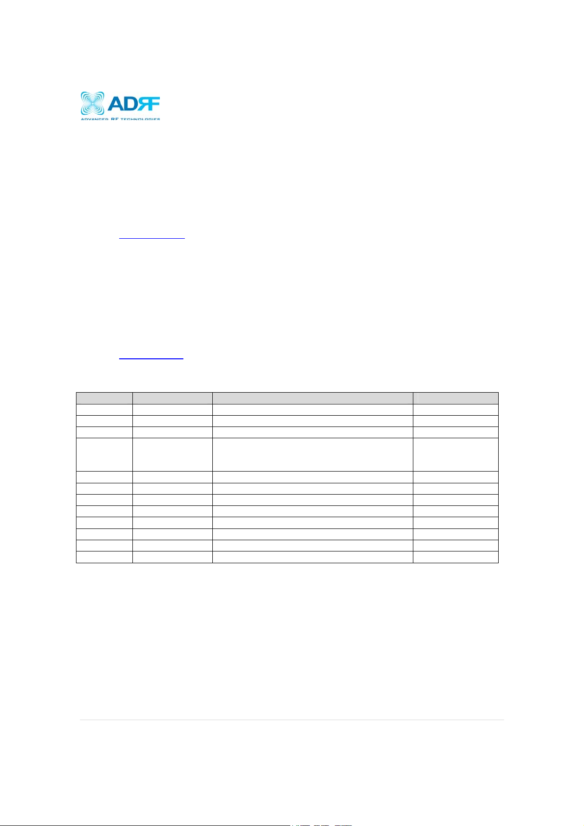
1.1.2 Parts List
Label Quantity Description
A 1 SDR Network Management System (NMS)
B Up to 3* Optional SDR Modules*
C 1 AC Power Cable
D 1 Ethernet Cable (Crossover)
E 1 Documentation CD**
F 1 Ground Cable
G 3 Channel Data Cable
H 1 Dipole Antenna
I 1 NMS Power Cable
J 6 Anchor Bolt
** CD includes: User Manual, Quick-Start Guide, and Troubleshooting Guide
B
F
G
I
J
* At least 1 module must be present in order to use SDR
Table 1 – Parts List
SDR Repeater
C
E
H
Figure A – SDR Repeater Parts List
Page | 7
Page 8
p
SDR Repeater
User Manual V0.4
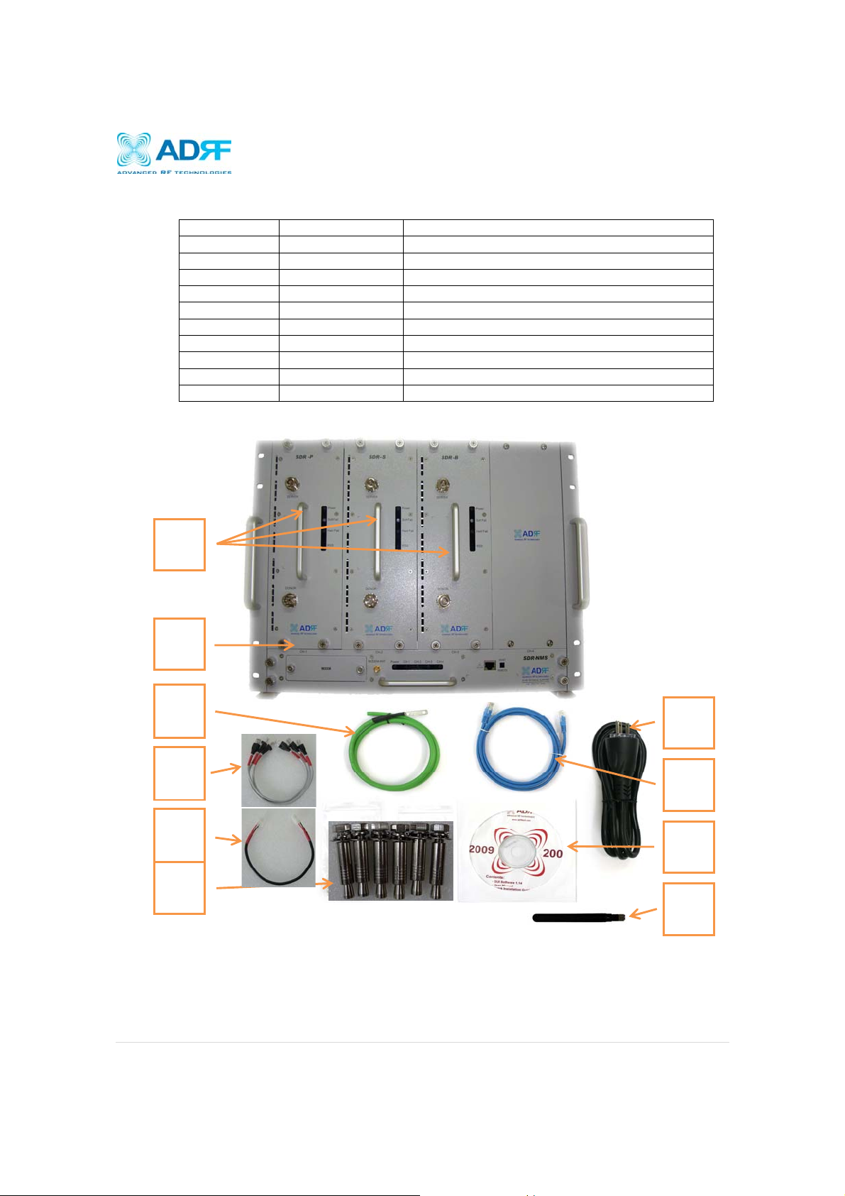
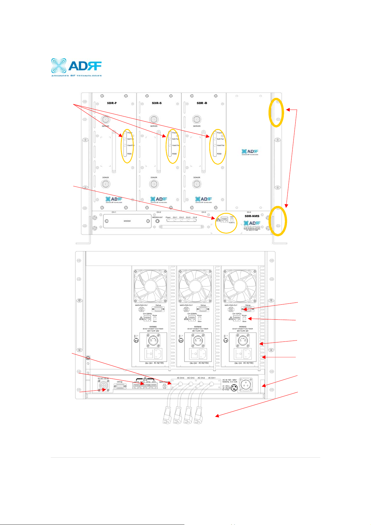
1.1.3 Repeater Quick View
LED indicator
Host / Remote
Switch & RJ-45
19” Rack
mount holes
ort
NMS Power Input
Port
NMS RJ-45 Hub
DC out for external
modem box
NMS Output
Power Port
RJ-45 Module
Communication Port
Battery Backup
Port
Module Power
Switch & AC IN port
Master AC IN
Module AC Power
Cords
Page | 8
Page 9
SDR Repeater
User Manual V0.4
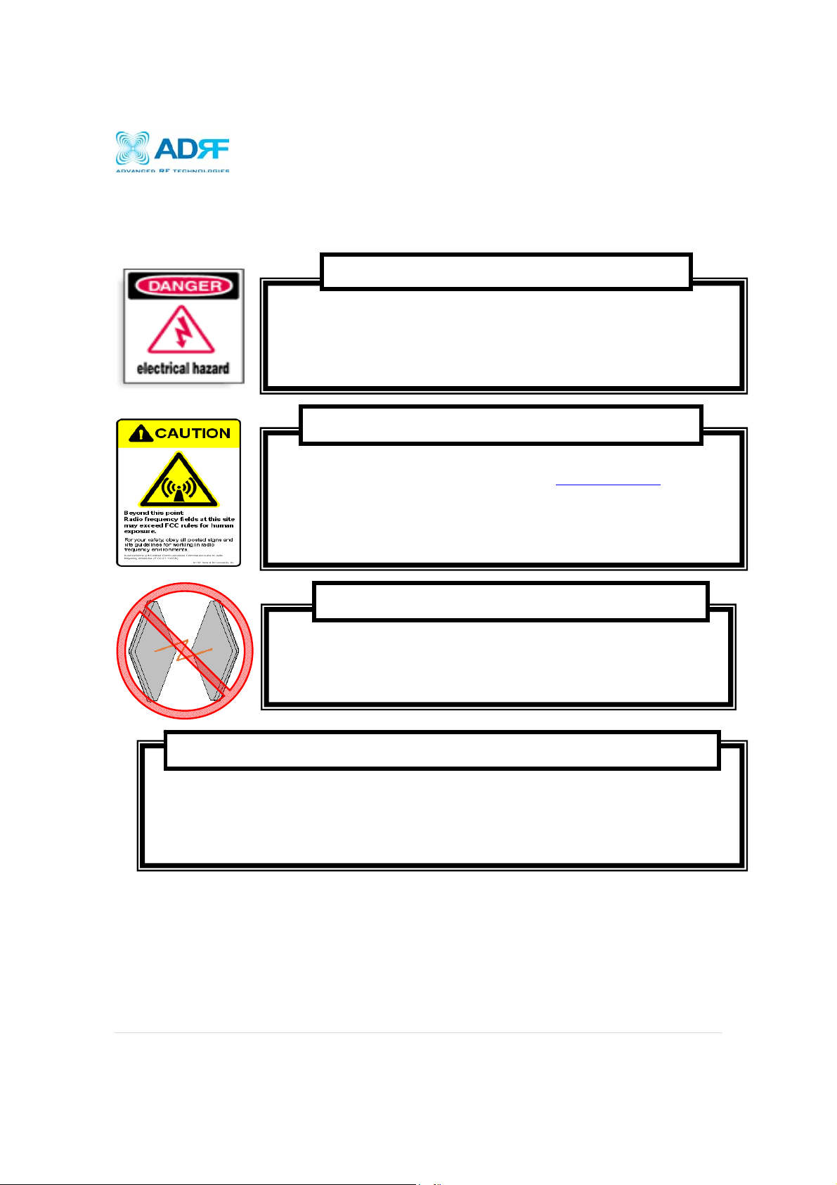
2. Warnings and Hazards
WARNING! ELECTRIC SHOCK
Opening the SDR could result in electric shock and may cause severe injury.
W ARNING! EXPOSURE TO RF
Working with the repeater while in operation , may expose the technician to RF electromagnetic fields that
exceed FCC rules for human exposure. Visit the FCC website at www.fcc.gov/oet/rfsafety
about the effects of exposure to RF electromagnetic fields.
to learn more
WARNING! DAMAGE TO REPEATER
Operating the SDR with antennas in very close proximity facing each other could lead to severe
damage to the repeater.
RF EXPOSURE & ANTENNA PLACEMENT Guidelines
Actual separation distance is determined upon gain of antenna used.
Please maintain a minimum safe distance of at least 140 cm while operating near the donor and the server antennas. Also, the donor
tenna needs to be mounted outdoors on a permanent structure.
an
Page | 9
Page 10
User Manual V0.4
SDR Repeater
WARRANTY
Opening or tampering the SDR will void all warranties.
Lithium Battery: CAUTION. RISK OF EXPLOSION IF BATTERY IS REPLACED BY INCORRECT TYPE.
DISPOSE OF USED BATTERIES ACCORDING TO INSTRUCTIONS.
Ethernet Instructions: This equipment is for indoor use only. All cabling should be limited to inside the
building.
FCC Part 15 Class A
NOTE: This equipment has been tested and found to comply with the limits for a Class A digital device,
pursuant to part 15 of the FCC Rules. These limits are designed to provide reasonable protection
against harmful interference when the equipment is operated in a commercial environment. This
equipment generates, uses, and can radiate radio frequency energy and, if not installed and used in
accordance with the instruction manual, may cause harmful interference to radio communications.
Operation of this equipment in a residential area is likely to cause harmful interference in which case
the user will be required to correct the interference at their own expense.
Double Pole/Neutral Fusing.
CAUTION
Page | 10
Page 11
SDR Repeater
User Manual V0.4
3. SDR Overview
3.1 Switches & Fault Indicators
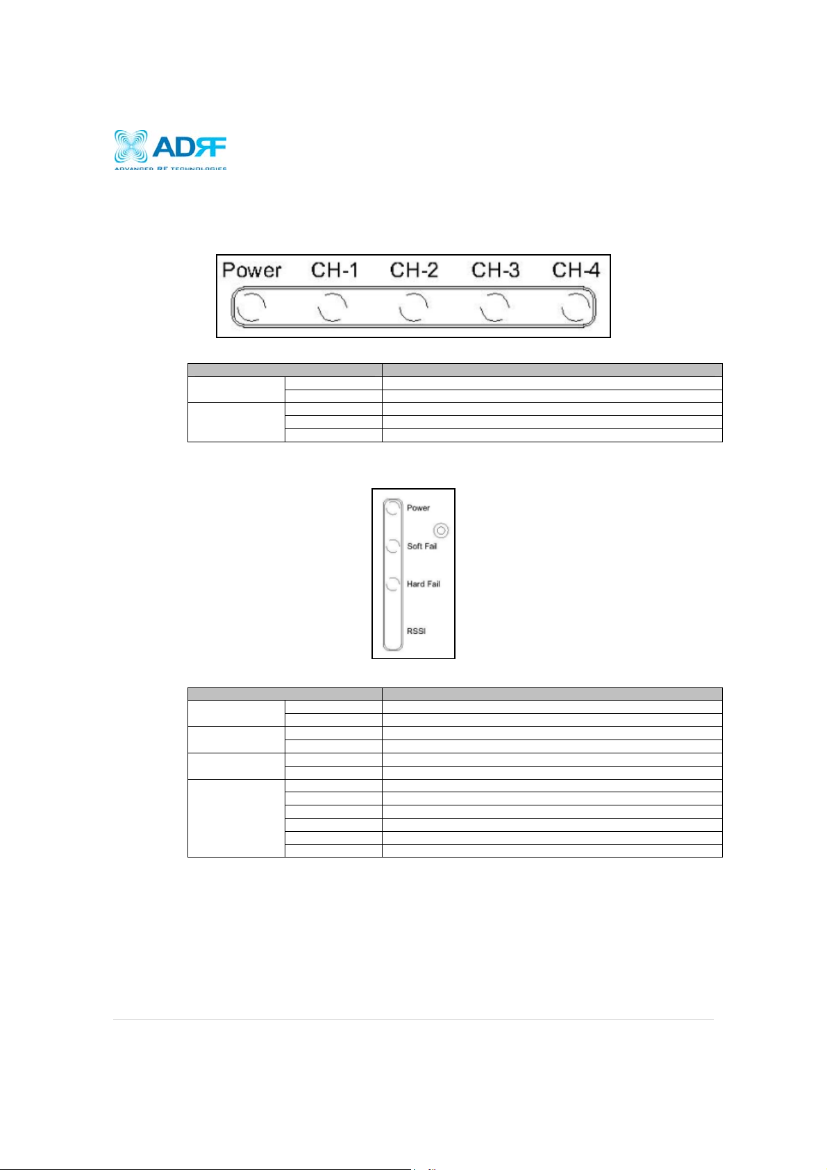
3.1.1 NMS and Module LED
SDR-NMS Specifications
CH-1, CH-2, CH-3,
CH-4
Solid Green NMS power is ON Power
OFF NMS is powered OFF
Solid Green Module has communication with NMS
Solid Red Module has a communication failure with NMS
OFF Module is powered OFF
Figure 1: NMS LED
3.1.2 Module LEDs
SDR has LEDs on the front of the module as shown below in Figure 2.
Figure 1: Module LED
SDR-Module Specifications
RSSI
Solid Green Module power is ON Power
OFF Module is powered OFF
Solid Yellow Soft Fail alarm exist in the system Soft Fail
OFF No Soft Fail alarm are present in the system
Solid Red Hard Fail alarm exist in the system Hard Fail
OFF No Hard Fail alarms are present in the system
Input < -85dBm Zero (0) bar On
Input < -75dBm One (1) bar On
Input < -65dBm Two (2) bars On
Input < -55dBm Three (3) bars On
Input < -45dBm Four (4) bars On
Input >= -45dBm Five (5) bars On
Page | 11
Page 12

SDR Repeater
User Manual V0.4
3.1.3 Message Board Alarms and Notification
Parameters Remark
Communication failure Internal Communication failure
RMF Field replaceable module failure
RESET Reset alarm
Heartbeat Heartbeat
OSC Oscillation detected
UL RSSI fail Power at coverage port too high
UL PLL fail UL Synthesizer failure
H/W fail Hardware failure
S/W fail Software failure
UL Emission fail UL Out-of-band emissions out of spec
DL RSSI fail Donor Power too high/low
ISO fail Low isolation
DL PLL fail DL Synthesizer failure
DL Spur fail DL Spurious emissions out of spec
Interfere Interferer power exceeded
Link Fail Communication error between the module and NMS
Over Temperature Module is above the normal operating temperature
Under Temperature Module is below the normal operating temperature
Fan Fail System has detected an issue with the fan
System Halt System is in a shutdown state due to a hard fail alarm
DL Signal not detected DL signal is below the specified level
DL Signal Low DL signal is below the specified level
Outband overload System has detected a strong out of band signal
Input overload In-band incoming signal strength is above max input level
Synthesizer Lock Fail Issue with internal system amp
DSP Fault System has detected an issue with the internal DSP chip
DL RF Power Input + gain does not match the output level (above delta of 6 dB)
Overpower Output level is above the max output levels
DL Oscillation Alarm Oscillation has been detected in the system
VSWR Power is being reflected back to the repeater
AC Fail Power supply is not operating within specs
DC Fail Power supply is not operating within specs
Over Current Power supply is not operating within specs
Page | 12
Page 13
SDR Repeater
User Manual V0.4
3.2 Switches and Ports
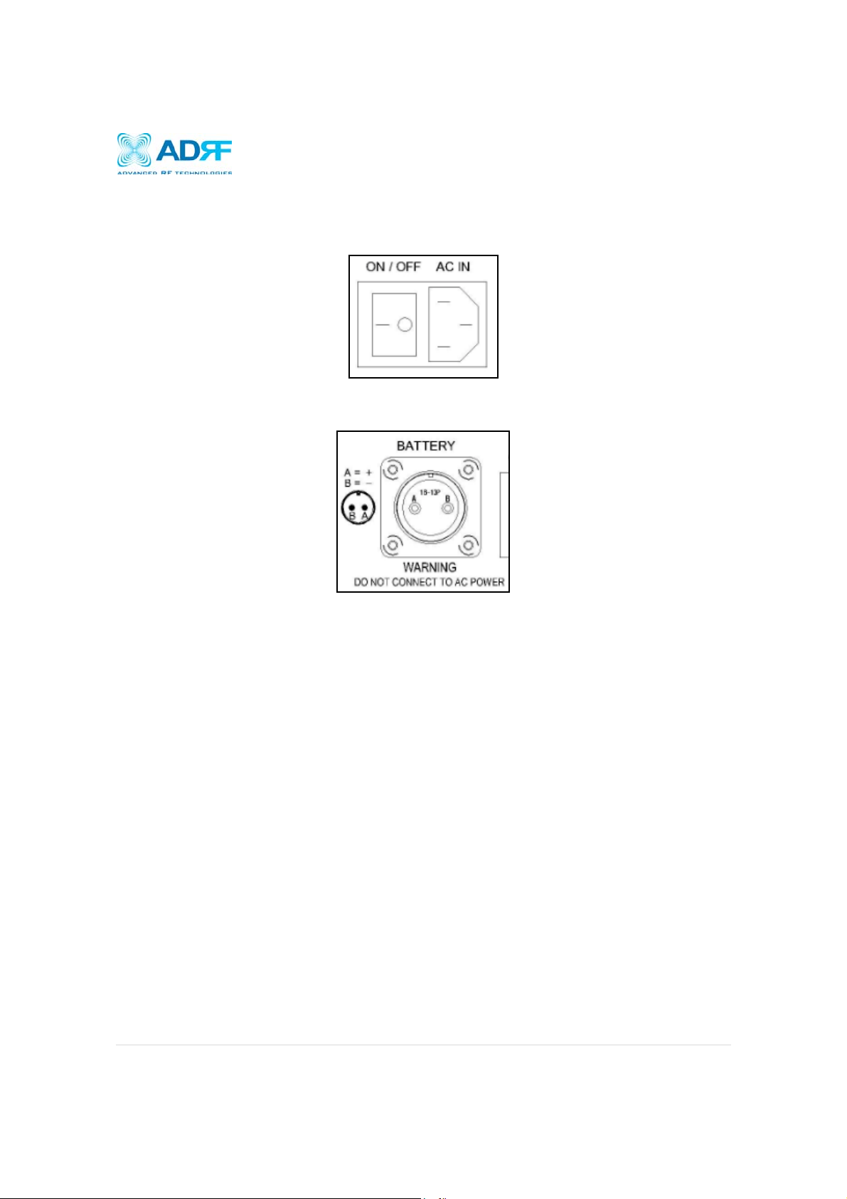
3.2.1 Power Switch
The AC Power on/off switch is located at the back of each individual module. Each module must be powered on
separated. The switch should be powered on after the repeater has been installed properly.
Figure 2: SDR Repeater Power Switch View
3.2.2 Back Up Battery Switch & Battery Port
Figure 3: Battery Backup Port
The SDR module can be connected to an ADRF-BBU (ADRF Battery Backup) to provide power during a power
failure. If an ADRF-BBU is utilized, connect the ADRF-BBU to the SDR via the external battery port as shown in
Figure 4.
(WARNING: The circuit switch on the ADRF-BBU must be set to OFF before connecting the ADRF-BBU
to the SDR to prevent damage to the repeater or the ADRF-BBU and personal injury.)
Note: Please contact ADRF Technical Support for assistance if you are unfamiliar with the installation
procedure of our battery box.
Page | 13
Page 14
SDR Repeater
User Manual V0.4
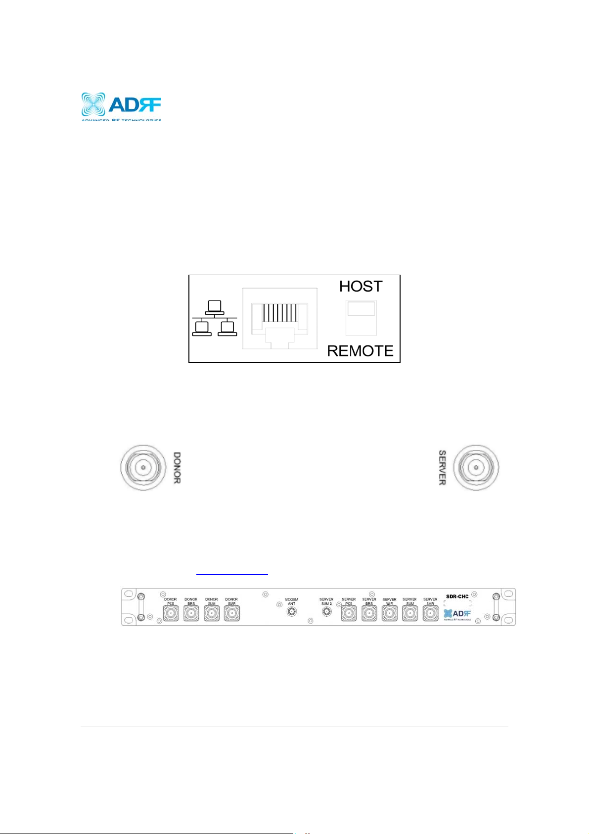
3.2.3 Ethernet Port and Host/Remote Switch
Ethernet Port
The Ethernet port can be used to communicate directly with the SDR using a RJ-45 crossover cable or can
also be used to connect the SDR to an external modem box.
Host/Remote Switch
The Host/Remote Switch allows the user to switch the default Repeater IP, Subnet Mask, and Gateway of the
repeater to an alternative setup. These settings can be adjusting by logging into the repeater in HOST mode
and configuring the settings under the Modem Box Setting section on the Install Page (section 4.4). Once the
settings are set, flipping the switch to the REMOTE position will reboot the repeater with the new alternate
settings. Please note that when the repeater is set to the REMOTE position, DHCP is disabled and the
repeater will not automatically assign an IP address to any device that connects directly to the repeater.
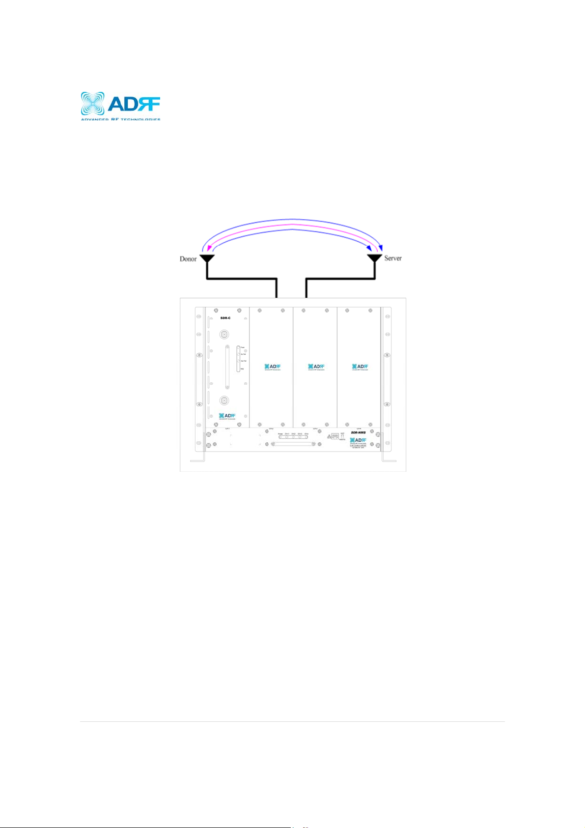
3.2.4 RF Ports
Module RF Ports
Donor and server antennas can be connected directly to the modules or the optional SDR-CHC (channel
combiner) can be used to split or combine signals.
Optional SDR-CHC
An optional channel combiner can be mounted directly above the SDR. The donor portion of the SDR-CHC
can be used to split up a combine donor signal into PCS, BRS, and SMR. The server portion of the SDRCHC can be used to combine the server signals (PCS, BRS, 2.4 GHz WIFI, and SMR) into the Server Sum
port. Please contact sales@adrftech.com
Figure 4: Ethernet Port and Host/Remote Switch
Figure 5: RFU RF port
if you are interested in purchasing the SDR-CHC.
Figure 6: Donor Combiner RF port
Page | 14
Page 15
SDR Repeater
User Manual V0.4
3.5 Installation
3.5.1 Wall Mount Procedure
Verify that the SDR and mounting hole are in
good condition
Remove all SDR modules from the system
Place the SDR chassis up against the wall so
that that module’s RF ports face the ceiling
Mount the SDR chassis to wall use the six (6)
mounting hold on the wall mount bracket
Install the SDR modules into the chassis and
secure the module by tightening the four (4)
hand screws
Connect the power and data cables at the
bottom on the SDR
Connect the GND cable
Connect the Antenna cable
Connect the Power cable
Wall Mount
Bracket
Figure 8: SDR
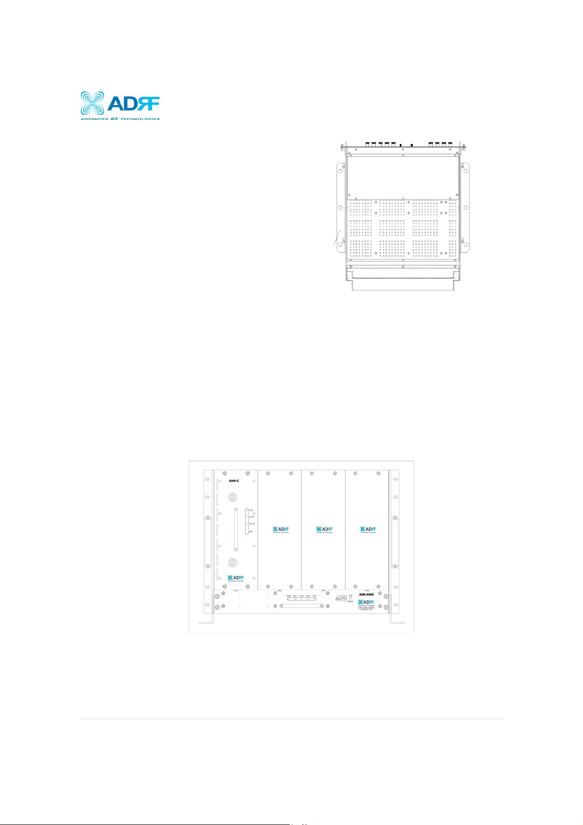
3.5.2 Rack Mount Procedure
Verify that the SDR and mounting hole are in good condition
Remove all SDR modules from the system
Install the SDR chassis into the 19” rack mount system
Screw the SDR chassis into the 19” rack mount system using the eight (8) mounting holes
Install the SDR modules into the chassis and secure the module by tightening the four (4) hand screws
Connect the power and data cables at the back of the SDR
Connect the GND cable
Connect the Antenna cable
Connect the Power cable
Wall Mount
Figure 7: SDR
Rack Mount
Page | 15
Page 16
SDR Repeater
User Manual V0.4
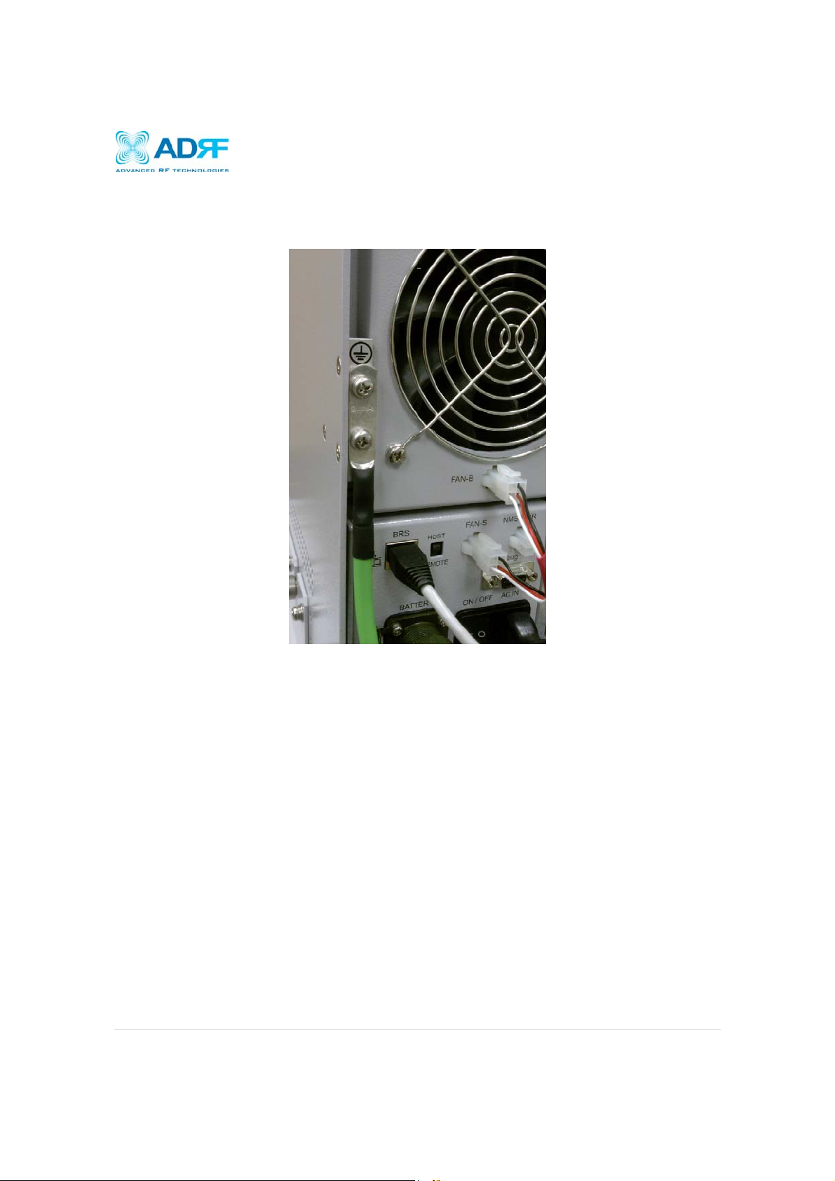
3.5.3 Grounding
Install the ground cable that has been included in the package at the back of the repeater as show in the
figure below.
Figure 8: Ground Cable Connection
Page | 16
Page 17
SDR Repeater
User Manual V0.4
3.5.4 Antenna Separation/Isolation
Separation between the antennas is necessary to prevent oscillation. Oscillation occurs when the signal entering the
system continually reenters, due to the lack of separation between the donor and server antennas. In other words, the
signal is being fed back into the system. This creates a constant amplification of the same signal. As a result, the
noise level rises above the signal level.
Figure 9: RF Repeater Oscillation
To prevent feedback, the donor and server antennas must be separated by an appropriate distance to provide
sufficient isolation. Isolation is attained by separating antennas a sufficient distance so that the output of one
antenna does not reach the input of the other. This distance is dependent on the gain of the repeater.
A sufficient isolation value is 13 ~ 15 dB greater than the maximum gain of the repeater. For example, if the gain of
the repeater is 50 dB, then an isolation of 63 ~ 65 dB or greater is required. In the same manner, because the SDR
has a maximum gain of 90 dB in case of SDR-24, it requires an isolation of at least 103 ~ 105 dB.
Page | 17
Page 18
SDR Repeater
User Manual V0.4
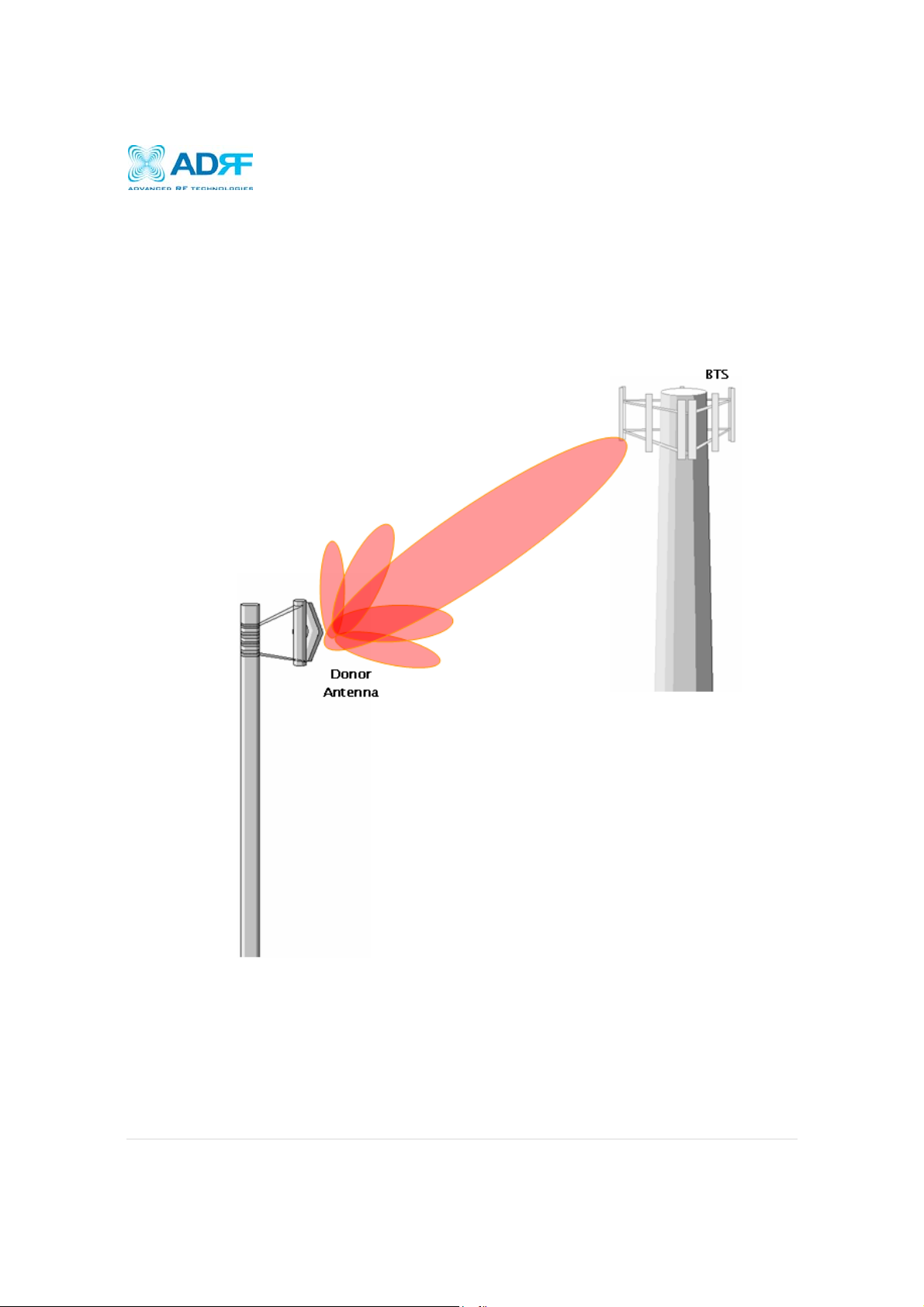
3.5.5 Line of Sight
The donor antenna which points towards the base station typically has a narrow beam antenna pattern. As a result,
a slight deviation away from the direction of the BTS can lead to less than optimum results. In addition, obstacles
between the repeater and the BTS may impair the repeater from obtaining any BTS signal. As a result, the repeater
cannot transmit signal to the coverage area. Therefore, a direct line of sight to the BTS for the donor antenna is vital
to the function of a repeater. For the same reason, placing the server antenna in direct line of sight of the coverage
area is also necessary.
Figure 12 - Direct Line of Sight to the BTS
Page | 18
Page 19

SDR Repeater
User Manual V0.4
4. SDR Web-GUI Setup
The Web-GUI allows the user to communicate with the repeater either locally or remotely. To connect to the repeater
locally, you will need a laptop with an Ethernet port and a RJ-45 crossover cable. To connect to the repeater remotely,
you will need to have an active internet connection and the repeater must have either an internal modem or an Omnibox
(ADRF Modem Box) connected to the repeater.
4.1 Repeater/PC Connection Using Web-GUI
A. Verify that your Local Area Connection is set to Obtain an IP address automatically under the Internet Protocol
(TCP/IP) properties
If you are connecting to the unit remotely (use of a modem), then skip steps A and B.
B. Connect the RJ-45 crossover cable between the laptop’s Ethernet port and the repeater’s Ethernet port
C. Launch an Internet Browser
D. Type the following IP address into the address bar of Microsoft Internet Explorer: http://192.168.63.1
If you are connecting to the unit remotely, then type the IP address of the modem to connect to the unit
E. The following login screen will appear:
If you are not the Administrator, please type in your assigned username & password which you should have
received from the Administrator.
The default username and password for the General User is adrf & adrf, respectively
And the Administrator User is admin & admin, respectively
Page | 19
Page 20
SDR Repeater
User Manual V0.4
4.2 Status Tab
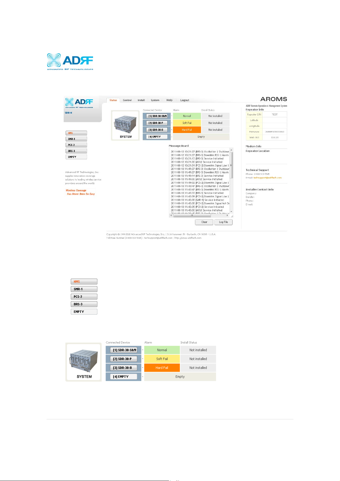
4.2.1 Status- NMS
Status- NMS
The NMS Status page provides an overall view of how the system is performing. From the NMS Status page,
the user can see if there are any alarms present on any of the modules.
4.2.1.1 Navigation Bar
The navigation bar located on the left hand side of the Web-GUI allows the user to switch between the various
modules that are connected to the system.
4.2.1.2 System Summary
The system summary provide a snapshot of the system is currently performing.
Connected Device- Displays what modules are connected to the SDR-NMS. Clicking on the buttons in
the column will take you to the Status page of that module.
Alarm- Displays the current alarm status of the individual modules
Page | 20
Page 21

SDR Repeater
User Manual V0.4
Install Status- Displays the installation status of the module
4.2.1.3 Message Board
Displays the system events of all connected modules.
4.2.1.4 Repeater Info / Modem Info / Technical Support / Installer Contact Info
Repeater Info- Displays the serial number, latitude, longitude, and firmware version of the repeater
Modem Info- If an internal modem is present, the modem information appears in this section
Technical Support- Displays ADRF’s Technical Support contact information
Installer Contact Info- Displays the contact information of the installer
Page | 21
Page 22

SDR Repeater
User Manual V0.4
4.2.2 Status- SMR, PCS, BRS
Status- SMR
Status- PCS
Page | 22
Page 23

SDR Repeater
User Manual V0.4
4.2.2.1 Band
This section displays the spectrum and technology that is being used. The band column displays the
bandwidth that has been selected. The downlink column displays the center frequency of the selected band.
The uplink column displays the center frequency of the selected band.
4.2.2.2 Power & Gain
This section displays the Input, Gain, and Output for both downlink and uplink.
4.2.2.3 Alarm
This section displays the alarm status for system alarms, RF alarms, and Power alarms. If an alarm is present
in the system, then the color of the alarm tab will change according to the type of failure.
Status- BRS
Page | 23
Page 24

SDR Repeater
User Manual V0.4
4.2.2.4 Message Board
Displays the 20 most recent events.
o Clear: Clears the content that is currently being displayed on the Message Board
o Log File: Downloads the system Log File (events and alarms) to your computer
4.2.2.5 Install, Modem, and Power Status
o Installation: Displays whether or not the installation routine has been run (Not Installed or Installed)
o Modem: Displays the status of the modem
Disabled- No internal modem is present
Not Connected- Internal modem is detected, but no connection to the network has been
established
Connected- Internal modem is detected and a connection to the network has been established
o Power: Displays the power source that is currently being used
4.2.2.6 Repeater Info / Modem Info / Repeater Location / Technical Support / Installer Contact Info
Repeater Info: Displays the serial number, latitude, longitude, firmware version,
Web-GUI version
Modem Info: Displays the internal modem information (ESN, MDN, IP)
Repeater Location: Displays the address where the repeater is installed
Technical Support: Displays ADRF’s Technical Support contact information
Installer Contact Info: Displays the installer’s name, phone and e-mail address
Note: Once successfully logged in, the repeater model name and the
site/cascade ID will be displayed on the top of all the windows (except for the
Main Window).
Page | 24
Page 25

SDR Repeater
User Manual V0.4
4.3 Control Tab
4.3.1 Control- NMS
4.3.1.1 Control Summary
This section allows the user to perform factory settings and reboot one module at a time.
4.3.1.2 Full System
This section allows the user to perform a full system reboot or a full system factory settings.
Control- NMS
Page | 25
Page 26

SDR Repeater
User Manual V0.4
4.3.2 Control- SMR, PCS, BRS
4.3.2.1 General Setting
o AGC ON: Enables or disables AGC (Automatic Gain Control)
o Downlink HPA ON: Enables or disables the DL HPA
o Uplink HPA ON: Enables or disabled the UL HPA
To enable any of the settings, click on the checkbox and click the Apply button.
Control- SMR , PCS, BRS
Page | 26
Page 27
SDR Repeater
User Manual V0.4
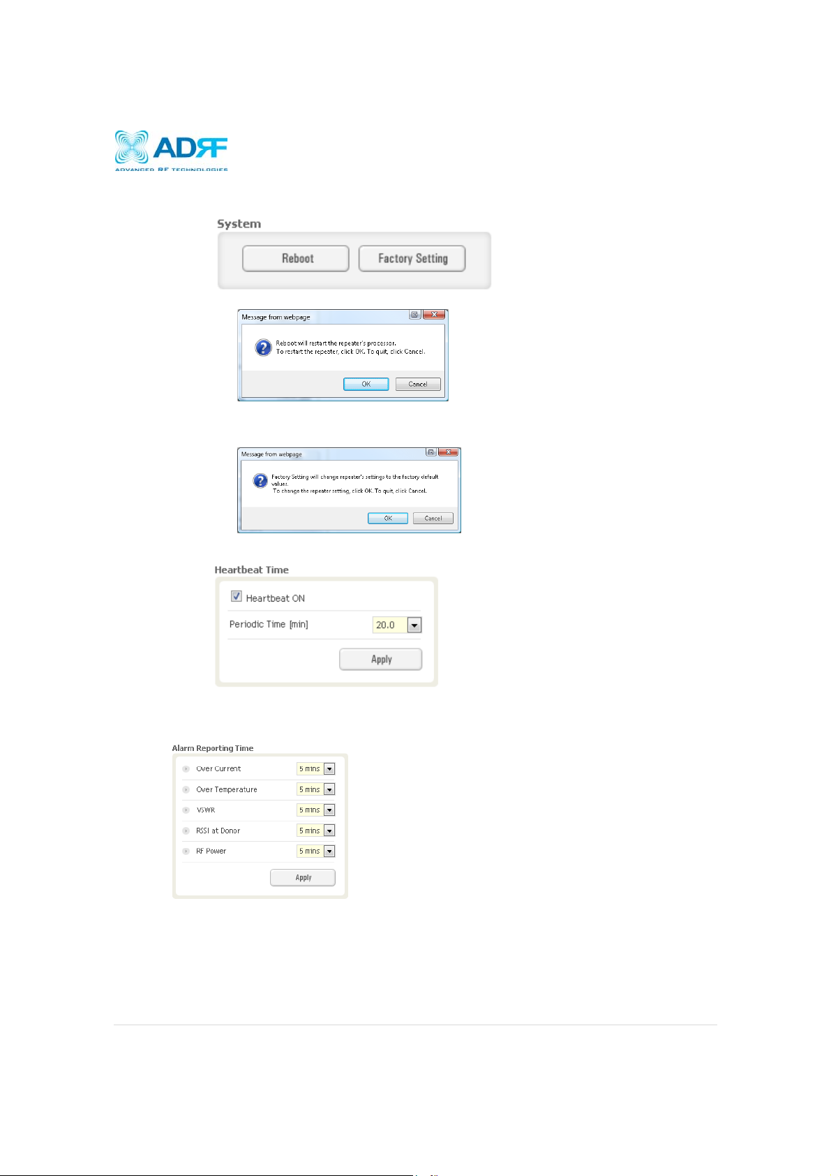
4.3.2.2 System
Reboot: Clicking the reboot button will have the following popup show up:
Click OK to reboot the repeater or click Cancel to exit out
Factory Setting: Resets the repeater to the original factory settings
4.3.2.3 Heartbeat Time
o Allows the user to enable or disable heartbeats from being sent out and also specify the time interval
4.3.2.4 Alarm Reporting Time
This section allows the user to specify the reporting time of the following alarms; Over Current, Over
Temperature, VSWR, RSSI at Donor, and RF Power. If the alarm is set to 5 mins, then the system will send
out an SNMP trap only if the alarm is continually present for a 5 minute period. If the alarm clears within this 5
minute period, then the SNMP trap will not be sent out. When the alarm reporting time is set to 0 min, the
SNMP trap will be set out immediately once the alarm is triggered. The alarm should be set to 0 min, only
when testing the monitoring function. Otherwise, all alarms should be set to 5 mins for normal operation.
Page | 27
Page 28

SDR Repeater
User Manual V0.4
4.3.2.5 Manual Gain Control
4.3.2.6 Alarm Setting
o Downlink Gain: Allows the DL gain to be adjusted manually when AGC is OFF
o Uplink Gain: Allows the UL gain to be adjusted manually when AGC is OFF
o Downlink AGC Level: Allows the user to set the DL gain when AGC is enabled
o Uplink AGC Level: Allows the user to set the UL gain when AGC is enabled
o DL Output ALC Level: Allows the user to set the Max output level when AGC is OFF
o DL Output ALC Offset: The amount of gain that the system has to work with before raising the gains
to match the DL Output ALC Level specified
o DL /UL Gain Balance ON: When enabled, the system will keep the delta value between the Downlink
and Uplink gain levels
o Downlink Signal Low: Allows the user to specify the how weak the signal can be before triggering a
“Downlink Signal Low” soft-fail alarm
o Downlink Signal Not Detected: Allows the user to specify the how weak the signal can be before
triggering a “Downlink Signal Not Detected” soft-fail alarm
o Downlink RF Power: Allows the user to set a maximum deviation value for the downlink RF power
For example, if the input signal is -50 dBm and the gain is set to 60 dB, the expected output
power should be 10 dBm. If the Downlink RF Power alarm value is set to 6dB, then if the
output power is below 4 dBm, then this will trigger a soft-fail alarm
o VSWR Alarm ON: Allow the user to enable/disable the VSWR alarm check
Page | 28
Page 29

SDR Repeater
User Manual V0.4
4.4 Install Tab
4.4.1 Install- NMS
4.4.1.1 Install Summary:
The auto installation routine can be run from this page by clicking on the Install button under the Auto
Installation column. This section also displays the Manager IP and Site ID for all the connected SDR modules.
Page | 29
Page 30

SDR Repeater
User Manual V0.4
4.4.1.2 Location
This section allows the user to input the latitude and the longitude of the repeater.
4.4.1.3 Modem Box Settings:
This section allows the user to specify an alternative Repeater IP, Subnet Mask, and Gateway settings. These
settings are enabled when the Host/Remote switch is set to the Remote position. When the Host/Remote
switch is changed, the repeater will reboot and will result in a temporary loss in coverage.
4.4.1.4 Repeater Location Info / Repeater Installer Info
This section allows the user to specify the address of the repeater and also the information of the installer.
4.4.1.5 Date & Time
This section allows the user to specify the current date and time.
Page | 30
Page 31
SDR Repeater
User Manual V0.4
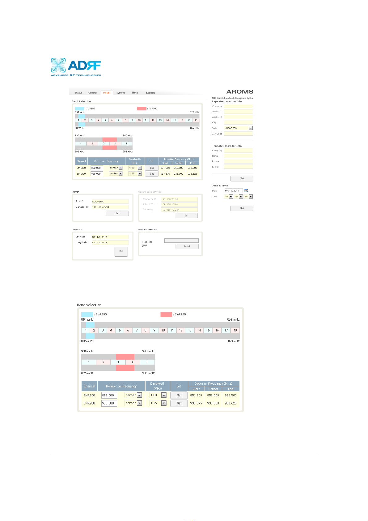
4.4.2 Install- SMR
The SMR Install page allows the user specify the desired frequncies by inputting the Reference Frequency and
Bandwidth. The SMR module supports 1 channel on the SMR800 and 1 channel on the SMR900. SMR800
bandwidth selections range from 1.25 to 18 MHz and SMR900 bandwidth selections range from 1.25 to 5 MHz.
4.4.2.1 Install- SMR Band Selection
To specify a frequency, input a DL reference frequency and select either start, center, or stop from the
dropdown menu. Select the desired bandwidth from the dropdown menu under the Bandwidth column and
then click Set.
Page | 31
Page 32

SDR Repeater
User Manual V0.4
Start Frequency:
If a start frequency is specifed, then this will be the beginning frequency of the band selection. Adding the
bandwidth value that is selected from the Bandwidth column will give you the end frequency of your band
selection.
Center Frequency:
Once a center frequncy is specified and a bandwidth is selected, the system will split the bandwidth value in
half and then add this to the center frequency to obtain your end frequency and also subtract this value to
obtain your start frequency.
Stop Frequency:
If a stop frequency is specified, then this will be the ending frequency of the band selection. Subtracting the
bandwidth value that is selected from the Bandwidth column will give you the start frequency of your band
selection.
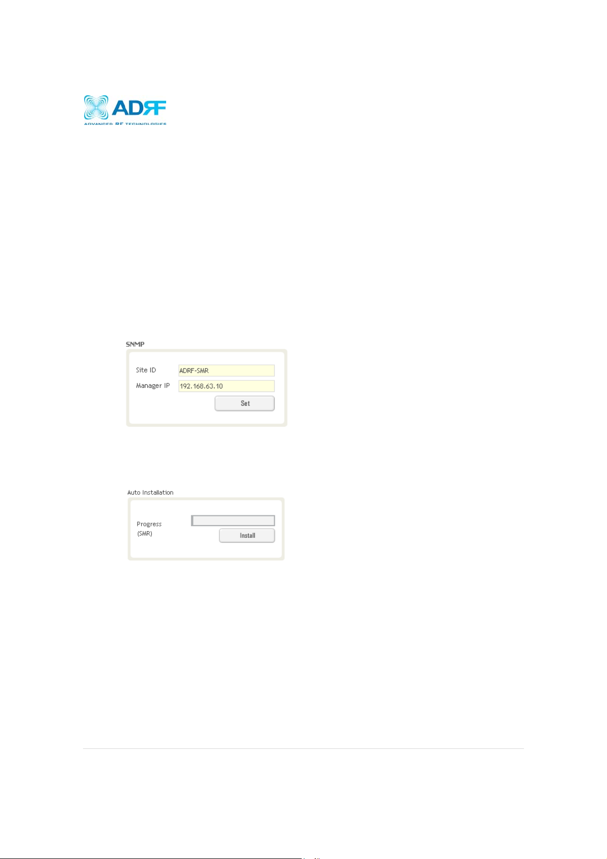
4.4.2.2 Install- SNMP
The SNMP section allows you to specify the Site ID and Manager IP. The Site-ID is the code that is used to
identify a particular module. The Manager IP field is where the user inputs the IP address of the NOC system
that is being used to monitor the SNMP traps.
4.4.2.3 Install- Auto Installation
The Auto Installation routine can be run by clicking on the Install button. The Auto Installation routine runs
basic system checks for propery functionaility.
Page | 32
Page 33

SDR Repeater
User Manual V0.4
4.4.3 Install- PCS
The PCS Install page allows the user specify the desired frequncies by inputting the Reference Frequency and
Bandwidth. The PCS module supports up to 3 non-contiguous bands. Bandwidth selection ranges from 1.25 to
18.75 MHz.
4.4.3.1 Install- PCS Band Selection
To specify a frequency, input a DL reference frequency and select either start, center, or stop from the
dropdown menu. Select the desired bandwidth from the dropdown menu under the Bandwidth column and
then click Set.
Page | 33
Page 34
SDR Repeater
User Manual V0.4
Start Frequency:
If a start frequency is specifed, then this will be the beginning frequency of the band selection. Adding the
bandwidth value that is selected from the Bandwidth column will give you the end frequency of your band
selection.
Center Frequency:
Once a center frequncy is specified and a bandwidth is selected, the system will split the bandwidth value in
half and then add this to the center frequency to obtain your end frequency and also subtract this value to
obtain your start frequency.
Stop Frequency:
If a stop frequency is specified, then this will be the ending frequency of the band selection. Subtracting the
bandwidth value that is selected from the Bandwidth column will give you the start frequency of your band
selection.
4.4.3.2 Install- SNMP
The SNMP section allows you to specify the Site ID and Manager IP. The Site-ID is the code that is used to
identify a particular module. The Manager IP field is where the user inputs the IP address of the NOC system
that is being used to monitor the SNMP traps.
4.4.3.3 Install- Auto Installation
The Auto Installation routine can be run by clicking on the Install button. The Auto Installation routine runs
basic system checks for propery functionaility.
Page | 34
Page 35

SDR Repeater
User Manual V0.4
4.4.4 Install- BRS
The BRS Install page allows the user to specify the desired frequncies by inputting the Reference Frequency and
Bandwidth. The BRS module supports 1 contiguous bands. Bandwidth selection ranges from 2.5 to 30 MHz.
4.4.4.1 Install- BRS Band Selection
Page | 35
Page 36

SDR Repeater
User Manual V0.4
To specify a frequency, input a DL reference frequency and select either start, center, or stop from the
dropdown menu. Select the desired bandwidth from the dropdown menu under the Bandwidth column and
then click Set.
Start Frequency:
If a start frequency is specifed, then this will be the beginning frequency of the band selection. Adding the
bandwidth value that is selected from the Bandwidth column will give you the end frequency of your band
selection.
Center Frequency:
Once a center frequncy is specified and a bandwidth is selected, the system will split the bandwidth value in
half and then add this to the center frequency to obtain your end frequency and also subtract this value to
obtain your start frequency.
Stop Frequency:
If a stop frequency is specified, then this will be the ending frequency of the band selection. Subtracting the
bandwidth value that is selected from the Bandwidth column will give you the start frequency of your band
selection.
4.4.4.2 Install- SNMP
The SNMP section allows you to specify the Site ID and Manager IP. The Site-ID is the code that is used to
identify a particular module. The Manager IP field is where the user inputs the IP address of the NOC system
that is being used to monitor the SNMP traps.
4.4.4.3 Install- Auto Installation
The Auto Installation routine can be run by clicking on the Install button. The Auto Installation routine runs
basic system checks for propery functionaility.
4.5 System
The System tab allows the user to perform firmware updates, upload closeout packages, view any changes to the system,
backup existing configuration, and add/remove user accounts, and change the login credentials of the Administrator.
Page | 36
Page 37

SDR Repeater
User Manual V0.4
4.5.1 System- Account
4.5.1.1 System: Account- Account Management
The Account Management section will allow the Administrator to delete any user account. Please note that
the Account Management section is only available if you are logged into the system as the Administrator. To
delete a user account click on the Account Management link and under the Delete column, click on the delete
button.
4.5.1.2 System: Account- New Account
The New account section allows the Administrator to create a new user account. Please note that the New
account section is only available if you are logged into the system as the Administrator. To create a new user
account click on the New account link and fill in the fields highlighted in yellow as shown below.
4.5.1.3 System: Account- Administrator
The Administrator section allows the Administrator to create additional Administrator accounts. Please note
that the Administrator section is only available if you are logged into the system as the Administrator.
Page | 37
Page 38

SDR Repeater
User Manual V0.4
4.5.1.4 System: Account- Change Password
The Change Password section allows the current user who is logged into the system to change their login
credentials.
4.5.2 System- Closeout Package
The closeout package section will allow the user to upload documents to the module. The maximum file size for
each upload is limited to 5 MB. The total amount of space available for uploading document is 100 MB. Please
do not use this section as the primary storage location of your documents. Documents may become unavailable
if the system goes down.
To upload documents to the module, click on the “Choose File” or “Browse” button and locate the file that you
would like to upload, then enter in a Description of the file being uploaded. Afterwards, click on the “Add File”
button to upload the file. Below is what you will see after the file upload. To delete the file, click on the delete
button located in the last column.
Page | 38
Page 39
SDR Repeater
User Manual V0.4
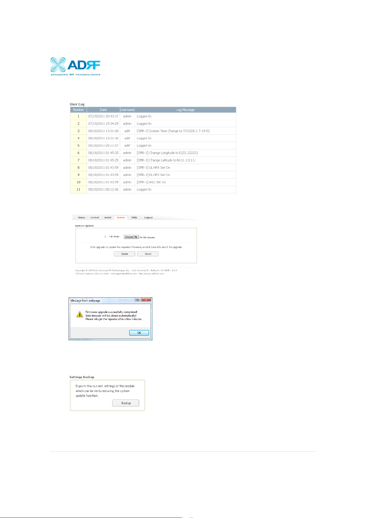
4.5.3 System- User Log
This section displays system events that have taken place. The User Log displays who has made the changes,
the time and date of when the event took place, and what changes were made to the system.
4.5.4 System: Update
To perform a firmware update, click on the System tab and the following screen will show up.
Click on the Choose File… button and locate the firmware file
Click on the Upload button to perform the firmware update
Once the firmware update is complete, the following popup message will appear:
4.5.5 System- Backup
The backup section allows the user to backup the settings on the module. To perform the backup, click on the
Backup button and you will be prompted to save the backup file. To restore the settings to the system, perform
an update using this file.
Page | 39
Page 40

User Manual V0.4
SDR Repeater
4.6 Help
If an internet connection is available, clicking on the Help Tab will redirect the user to our Technical Support page.
4.7 Logout
Clicking the Logout button will log the current user off the system.
Page | 40
Page 41

User Manual V0.4
SDR Repeater
5. Maintenance Guide for SDR Repeater
5.1 Periodic Inspection Checklist
a) Check for loose connections between the repeater and antennas. If connections are loose, make sure that all
connections are tightly fastened properly.
b) Cables and connectors are in good condition.
c) Ensure that the repeater brackets are in good. condition and that the repeater is securely fastened
5.2 Preventive Measures for Optimal Operation
5.2.1 Recommendations
Perform the Periodic Inspection Checklist quarterly or semi-annually.
5.2.2 Precautions
Do not operate the repeater with the antennas in extremely close proximity to one another as this may
cause damage to the repeater.
Do not change the parameters unless instructed to do so by an authorized supervisor.
Do not move the repeater unless instructed to do so by an authorized supervisor.
Do not detach any cables to the repeater unless repair of respective components is necessary.
Page | 41
Page 42

User Manual V0.4
SDR Repeater
6. Warranty and Repair Policy
6.1 General Warranty
The SDR carries a Standard Warranty period of three (3) years unless indicated otherwise on the package or in the
acknowledgment of the purchase order.
6.2 Limitations of Warranty
Your exclusive remedy for any defective product is limited to the repair or replacement of the defective product. Advanced
RF Technologies, Inc. may elect which remedy or combination of remedies to provide in its sole discretion. Advanced RF
Technologies, Inc. shall have a reasonable time after determining that a defective product exists to repair or replace the
problem unit. Advanced RF Technologies, Inc. warranty applies to repaired or replaced products for the balance of the
applicable period of the original warranty or ninety days from the date of shipment of a repaired or replaced product,
whichever is longer.
6.3 Limitation of Damages
The liability for any defective product shall in no event exceed the purchase price for the defective product.
6.4 No Consequential Damages
Advanced RF Technologies, Inc. has no liability for general, consequential, incidental or special damages.
6.5 Additional Limitation on Warranty
Advanced RF Technologies, Inc. standard warranty does not cover products which have been received improperly
packaged, altered, or physically damaged. For example, broken warranty seal, labels exhibiting tampering, physically
abused enclosure, broken pins on connectors, any modifications made without Advanced RF Technologies, Inc.
authorization, will void all warranty.
6.6 Return Material Authorization (RMA)
No product may be returned directly to Advanced RF Technologies, Inc. without first getting an approval from Advanced
RF Technologies, Inc. If it is determined that the product may be defective, you will be given an RMA number and
instructions in how to return the product. An unauthorized return, i.e., one for which an RMA number has not been issued,
will be returned to you at your expense. Authorized returns are to be shipped to the address on the RMA in an approved
shipping container. You will be given our courier information. It is suggested that the original box and packaging materials
should be kept if an occasion arises where a defective product needs to be shipped back to Advanced RF Technologies,
Inc. To request an RMA, please call (800) 313-9345 or send an email to techsupport@adrftech.com.
Page | 42
Page 43
SDR Repeater
User Manual V0.4
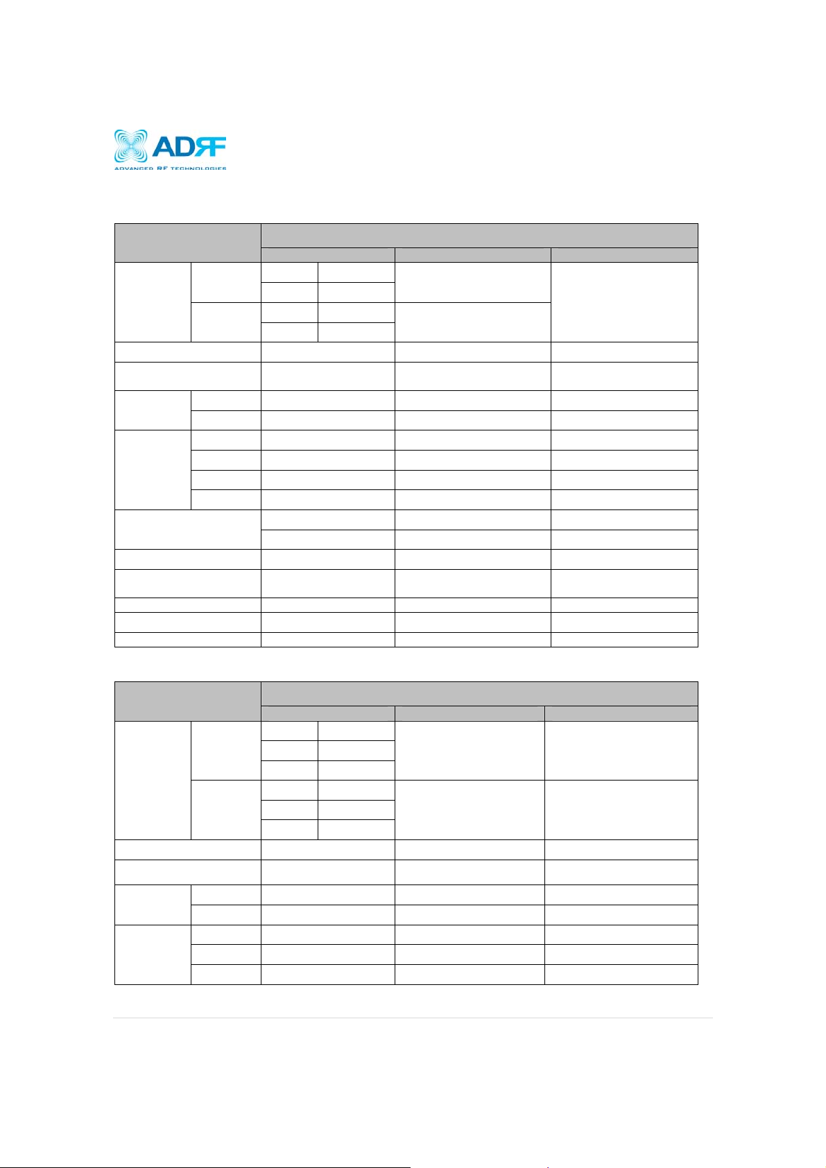
7. Specifications
7.1 Electrical Specifications
Specifications
Specifications
2502~2690MHz
2.5MHz Step Max 30 MHz
(Continuous 1ch)
≤ ±1.0dB
1MHz@ 40dBc
3.5MHz@ 80dBc
1.25MHz Step, Max 18.75 MHz
(Non-Contiguous 3ch)
Parameters
Frequency
Range
Frequency Error ≤ ±0.05ppm ≤ ±0.02ppm
Band Selection
Gain Flatness
Gain
Composite Output power
Delay 8us 6us 6us
Roll offs 0.5MHz@ 65dBc 1MHz@ 50dBc
Noise Figure( Uplink Only) 6dB@ Max Gain 6dB@ Max Gain 6dB@ Max Gain
VSWR (Input Only) 1.5:1 1.5:1 1.5:1
Sync Detection Level <-85dBm Typ (Max -90dBm)
DL
UL
Full band ≤ ±1.5dB ≤ ±1.5dB ≤ ±1.5dB
Each band ≤ ±1.5dB ≤ ±1.5dB ≤ ±1.5dB
Maximum 80dB 90dB 90dB
Step 0.5dB 0.5dB 0.5dB
Range 30dB 30dB 30dB
To le r a nc e
SDR-S (SMR800/900) SDR-P (PCS) SDR-B (BRS)
SMR800 851~869MHz
SMR900 935~940MHz
SMR800 806~824MHz
SMR900 896~901MHz
0.25MHz Step, Max 18
MHz
≤ ±1.0dB ≤ ±1.0dB
24dBm (SDR-24) 24dBm (SDR-24) 24dBm (SDR-24)
30dBm (SDR-30) 30dBm (SDR-30) 30dBm (SDR-30)
1930~1995MHz
1850~1915MHz
1.25MHz Step Max 18.75 MHz
(Non-Contiguous 3ch)
Parameters
DL
Frequency
Range
UL
Frequency Error ≤ ±0.05ppm ≤ ±0.05ppm ≤ ±0.05ppm
Band Selection
Gain Flatness
Gain
Full band ≤ ±1.5dB ≤ ±1.5dB ≤ ±1.5dB
Each band ≤ ±1.5dB ≤ ±1.5dB ≤ ±1.5dB
Maximum 90dB 90dB 90dB
Step 0.5dB 0.5dB 0.5dB
Range 30dB 30dB 30dB
SDR-700 (LTE) SDR-C (CELL) SDR-A (AWS)
Upper C 746~757MHz
Lower A 728~734MHz
Lower B 734~740MHz
Upper C 776~787MHz
Lower A 698~704MHz
Lower B 704~710MHz
0.25MHz Step, Max 12 MHz
(Non-Contiguous 2ch)
869~894MHz 2110~2155MHz
824~849MHz 1710~1755MHZ
0.25MHz Step, Max 25 MHz
Page | 43
Page 44

SDR Repeater
User Manual V0.4
To le r a nc e
Composite Output power
Delay 6.5us 7us 6us
Roll offs 1MHz@ 50dBc
Noise Figure( Uplink Only) 6dB@ Max Gain 6dB@ Max Gain 6dB@ Max Gain
VSWR (Input Only) 1.5:1 1.5:1 1.5:1
EVM ≤ 12.5% ≤ 12.5% ≤ 12.5%
≤ ±1.0dB ≤ ±1.0dB
24dBm (SDR-24) 24dBm (SDR-24) 24dBm (SDR-24)
30dBm (SDR-30) 30dBm (SDR-30) 30dBm (SDR-30)
0.5MHz@ 30dBc,
1MHz@ 50dBc
≤ ±1.0dB
1MHz@ 50dBc
7.2Mechanical Specifications
Parameters Specifications Remarks
Module 18.2 x 11.6 x 4.2 in
Size
NMS 17.0 x 16.7 x 2.3 in
Chassis 19.0 x 19.5 x 14 in
Module 21 lbs
Weight
NMS 7 lbs
Chassis 26 lbs
Connector
Type
Input / Output
Sum Port
Ethernet RJ45 Female
N Female
Frame ground M5 Screw
Mount type Wall mount or 19” rack mount
Security Physical Cabinet
7.3 Power Specifications
Parameters Specifications Remarks
AC Power 100~120V AC, 60Hz
DC Power
-40 ~ -60V DC
+20 ~ +30V DC
Option
7.4 Environment Specifications
Parameters Specifications Remarks
Operating Temperature
+30 ~ +122F
+0 ~ +50C
Relative Humidity +5 ~ +95%
Industrial dust Telcodia GR63-core
7.5 Warranty & Certificates
Parameters Specifications Remarks
MTBF > 100,000 hours
Page | 44
Page 45

SDR Repeater
User Manual V0.4
UL 60950
Certificates
FCC CFR47 part 24
FCC CFR47 part 15
FCC CFR47 part 90
Page | 45
Page 46

SDR Repeater
User Manual V0.4
Appendix A: Mechanical Drawing
Figure 10: SDR mechanical drawing
Page | 46
Page 47

SDR Repeater
User Manual V0.4
Appendix B: Shutdown Retry Logic
The function of the built-in shutdown routine is to protect the repeater from any further damage from a hard-fail that the
system may be experiencing.
Within 5 seconds of a hard-fail alarm being detected, the repeater will start the shutdown routine. The repeater will shut
down by powering of the HPAs (high-powered amplifiers) for 30 seconds.
After 30 seconds have elapsed, the repeater will power on the HPAs and check to see if the hard-fail alarm still exist. If
the hard-fail alarm still exists, then the repeater will shut down for 1 minute (double the time of the previous shutdown
time).
After 1 minute has elapsed, the repeater will power on the HPAs and check to see if the hard-fail alarm still exist. If the
hard-fail alarm still exists, then the repeater will shut down for 2 minutes (double the time of the previous shutdown time).
The shutdown routine will repeat itself a total of 10 times. If the hard-fail alarm still exists after the 10
repeater will turn off its HPAs permanently until a reset is performed or factory set is executed.
th
retry, then the
Page | 47
Page 48
MPE Information
Warning: Exposure to Radio Frequency Radiation The radiated output power
of this device is far below the FCC radio frequency exposure limits.
Nevertheless, the device should be used in such a manner that the potential
for human contact during normal operation is minimized. In order to avoid
the possibility of exceeding the FCC radio frequency exposure limits, human
proximity to the antenna should not be less than
operation. The gain of the antenna is 16 dBi.
transmitter must not be
co-located or operating in conjunction with any other
140cm d
The antenna(s) used for this
antenna or transmitter.
,&:DUQLQJ
7KLVGHYLFHFRPSOLHVZLWK,QGXVWU\&DQDGDOLFHQFHH[HPSW566VWDQGDUGV
2SHUDWLRQLVVXEMHFWWRWKHIROORZLQJWZRFRQGLWLRQVWKLVGHYLFHPD\QRWFDXVHLQWHUIHUHQFHDQG
WKLVGHYLFHPXVWDFFHSWDQ\LQWHUIHUHQFHLQFOXGLQJLQWHUIHUHQFHWKDWPD\FDXVHXQGHVLUHGRSHUDWLRQRIWKHGHYLFH
/HSUpVHQWDSSDUHLOHVWFRQIRUPHDX[&15G,QGXVWULH&DQDGDDSSOLFDEOHVDX[DSSDUHLOVUDGLRH[HPSWVGHOLFHQFH
/H[SORLWDWLRQHVWDXWRULVpHDX[GHX[FRQGLWLRQVVXLYDQWHVODSSDUHLOQHGRLWSDVSURGXLUHGHEURXLOODJHHW
OXWLOLVDWHXUGHODSSDUHLOGRLWDFFHSWHUWRXWEURXLOODJHUDGLRpOHFWULTXHVXEL
PrPHVLOHEURXLOODJHHVWVXVFHSWLEOHGHQFRPSURPHWWUHOHIRQFWLRQQHPHQW
uring normal
ⓒ SAMSUNG Electronics Co., Ltd.
 Loading...