

Advanced Power Technology APT APT60D30LCT Datasheet
1 3
2
1- Anode 1
2- Common Cathode
Back of Case -Cathode
3- Anode 2
1
TO-264
APT60D30LCT 300V 60A
3
2
ULTRAFAST SOFT RECOVERY RECTIFIER DIODES
PRODUCT APPLICATIONS
• Parallel Diode
-Switchmode Power Supply
-Inverters
• Free Wheeling Diode
-Motor Controllers
-Converters
• Snubber Diode
• Uninterruptible Power Supply (UPS)
PRODUCT FEATURES
• Ultrafast Recovery Times
• Soft Recovery Characteristics
• Popular TO-264 Package
• Low Forward Voltage
• High Blocking Voltage
• 48 Volt Output Rectifiers
• High Speed Rectifiers
• Low Leakage Current
MAXIMUM RATINGS All Ratings Are Per Leg: TC = 25°C unless otherwise specified.
PRODUCT BENEFITS
• Low Losses
• Low Noise Switching
• Cooler Operation
• Higher Reliability Systems
• Increased System Power
Density
Symbol
V
V
RRM
V
RWM
IF(AV)
(RMS)
I
F
I
FSM
TJ,T
T
Characteristic / Test Conditions
Maximum D.C. Reverse Voltage
R
Maximum Peak Repetitive Reverse Voltage
Maximum Working Peak Reverse Voltage
Maximum Average Forward Current (T
RMS Forward Current
Non-Repetitive Forward Surge Current (TJ = 45°C, 8.3mS)
Operating and StorageTemperature Range
STG
Lead Temperature: 0.063" from Case for 10 Sec.
L
ADVANCE TECHNICAL
INFORMATION
STATIC ELECTRICAL CHARACTERISTICS
Symbol
V
I
RM
Characteristic / Test Conditions
Maximum Forward Voltage I
F
Maximum Reverse Leakage Current VR = VR Rated
= 90°C, Duty Cycle = 0.5)
C
I
= 60A
F
= 120A
F
IF = 60A, TJ = 150°C
VR = VR Rated, TJ = 125°C
APT60D30LCT
300
60
60
600
-55 to 150
300
MIN TYP MAX
1.4
1.4
1.2
250
500
UNIT
Volts
Amps
°C
UNIT
Volts
µA
C
L
USA 405 S.W. Columbia Street Bend, Oregon 97702-1035 Phone: (541) 382-8028 FAX: (541) 388-0364
EUROPE Chemin de Magret F-33700 Merignac - France Phone: (33)5 57 9215 15 FAX: (33)556 47 9761
Junction Capacitance, V
T
Series Inductance (Lead to Lead 5mm from Base)
S
= 200V
R
APT Website - http://www.advancedpower.com
140
10
pF
nH
053-4053 Rev- 6-2001
DYNAMIC CHARACTERISTICS
APT60D30LCT
Symbol
t
rr1
t
rr2
t
rr3
t
fr1
t
fr2
I
RRM1
I
RRM2
Q
rr1
Q
rr2
V
fr1
V
fr2
diM /dt
Characteristic
Reverse Recovery Time, I
= 1.0A, diF/dt = -15A/µs, VR = 30V, TJ = 25°C
F
Reverse Recovery Time TJ = 25°C
= 60A, diF/dt = -480A/µs, VR = 180V TJ = 100°C
I
F
Forward Recovery Time TJ = 25°C
= 60A, diF/dt = 480A/µs, VR = 180V TJ = 100°C
I
F
Reverse Recovery Current TJ = 25°C
= 60A, diF/dt = -480A/µs, VR = 180V TJ = 100°C
I
F
Recovery Charge T
= 25°C
J
IF = 60A, diF/dt = -480A/µs, VR = 180V TJ = 100°C
Forward Recovery Voltage T
= 60A, diF/dt = 480A/µs, VR = 180V TJ = 100°C
I
F
= 25°C
J
Rate of Fall of Recovery Current TJ = 25°C
= 60A, diF/dt = -480A/µs, VR = 180V TJ = 100°C
I
F
MIN TYP MAX
53 TBD
45
70
182
182
12 17
18 25
315
750
7.5
7.5
690
845
UNIT
ns
Amps
nC
Volts
A/µS
THERMAL AND MECHANICAL CHARACTERISTICS
qJC
qJA
Characteristic / Test Conditions
Junction-to-Case Thermal Resistance
ADVANCE TECHNICAL
Junction-to-Ambient Thermal Resistance
Package Weight
T
INFORMATION
Maximum Mounting Torque (Screw Type = 6-32 or 3mm Machine)
Symbol
R
R
W
Torque
APT Reserves the right to change, without notice, the specifications and information contained herein.
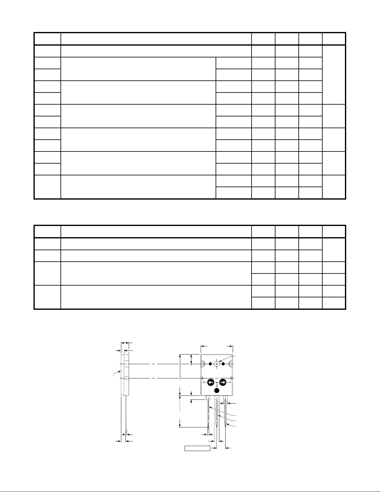
TO-264 Package Outline
4.60 (.181)
5.21 (.205)
1.80 (.071)
2.01 (.079)
5.79 (.228)
6.20 (.244)
25.48 (1.003)
26.49 (1.043)
19.51 (.768)
20.50 (.807)
3.10 (.122)
3.48 (.137)
MIN TYP MAX
0.66
40
0.35
9.9
10
1.1
UNIT
°C/W
oz
gm
lb•in
N•m
2.29 (.090)
Common Cathode
0.48 (.019)
0.84 (.033)
2.59 (.102)
3.00 (.118)
Dimensions in Millimeters and (Inches)
APT's devices are covered by one or more of the following U.S.patents: 4,895,810 5,045,903 5,089,434 5,182,234 5,019,522 5,262,336
053-4053 Rev- 6-2001
2.29 (.090)
2.69 (.106)
19.81 (.780)
21.39 (.842)
0.76 (.030)
1.30 (.051)
2.79 (.110)
3.18 (.125)
5.45 (.215) BSC
2-Plcs.
5,256,583 4,748,103 5,283,202 5,231,474 5,434,095 5,528,058
2.69 (.106)
Anode 1
Common Cathode
Anode 2
 Loading...