

Advanced Power Technology APT APT50GF60BR Datasheet
APT50GF60BR
APT50GF60BR
600V 75A
Fast IGBT
The Fast IGBT is a new generation of high voltage power IGBTs. Using
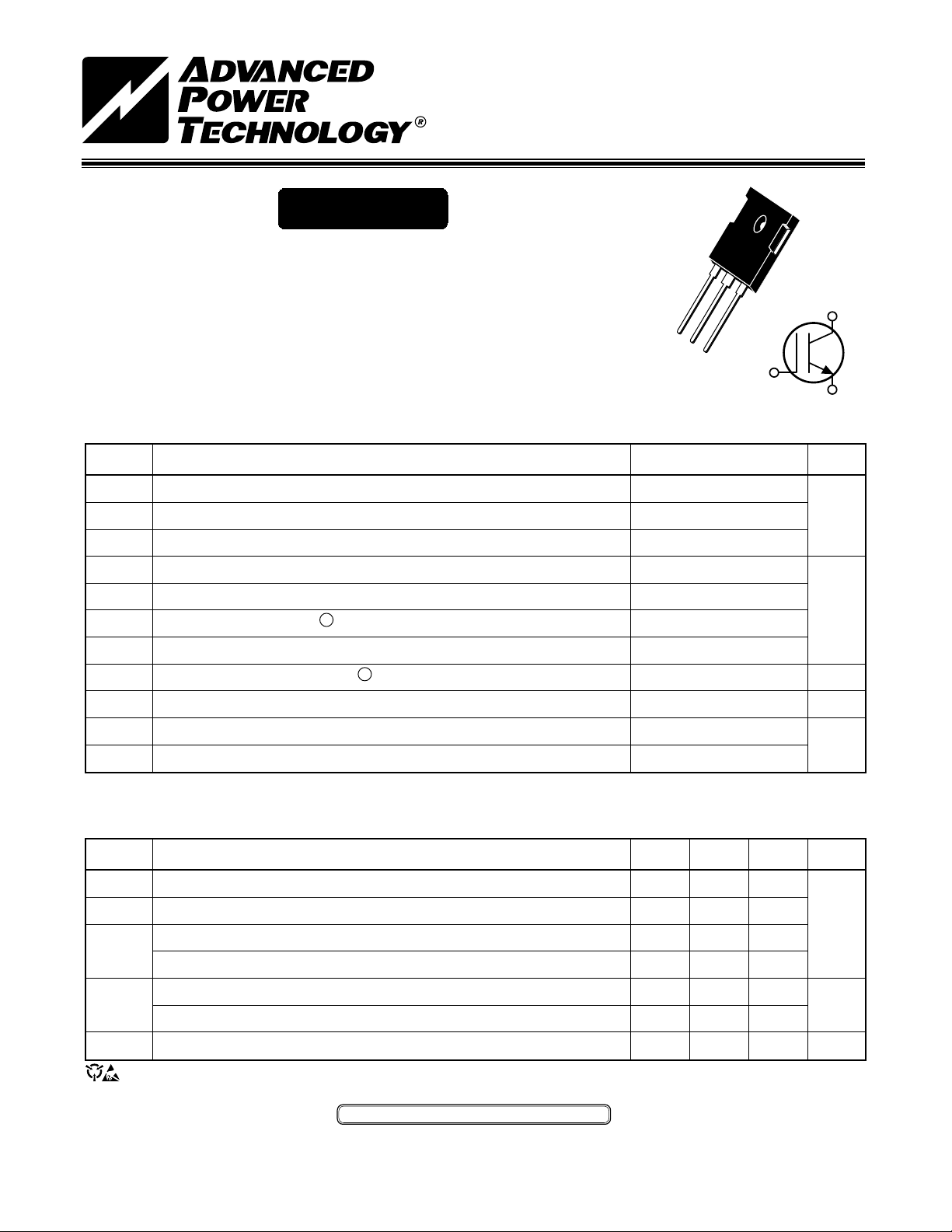
TO-247
Non-Punch Through Technology the Fast IGBT offers superior ruggedness,
fast switching speed and low Collector-Emitter On voltage.
C
• Low Forward Voltage Drop • High Freq. Switching to 20KHz
• Low Tail Current • Ultra Low Leakage Current
• Avalanche Rated • RBSOA and SCSOA Rated
G
C
E
G
E
MAXIMUM RATINGS All Ratings: TC = 25°C unless otherwise specified.
Symbol
V
CES
V
CGR
V
I
C1
I
C2
I
CM
I
LM
E
P
TJ,T
T
Parameter
Collector-Emitter Voltage
Collector-Gate Voltage (R
Gate-Emitter Voltage
GE
Continuous Collector Current @ T
Continuous Collector Current @ T
Pulsed Collector Current
RBSOA Clamped Inductive Load Current @ R
Single Pulse Avalanche Energy
AS
Total Power Dissipation
D
Operating and Storage Junction Temperature Range
STG
Max. Lead Temp. for Soldering: 0.063" from Case for 10 Sec.
L
= 20KW)
GE
= 25°C
C
= 90°C
C
1
@ TC = 25°C
2
= 11W TC = 125°C
g
APT50GF60BR
600
600
±20
75
50
160
100
75
300
-55 to 150
300
UNIT
Volts
Amps
mJ
Watts
°C
STATIC ELECTRICAL CHARACTERISTICS
Symbol
BV
VGE(TH)
V
CE
I
CES
I
GES
USA 405 S.W. Columbia Street Bend, Oregon 97702-1035 Phone: (541) 382-8028 FAX: (541) 388-0364
EUROPE Chemin de Magret F-33700 Merignac - France Phone: (33)5 579215 15 FAX: (33)5 56 47 9761
Characteristic / Test Conditions
Collector-Emitter Breakdown Voltage (V
CES
Gate Threshold Voltage (V
Collector-Emitter On Voltage (VGE = 15V, IC = 50A, Tj = 25°C)
(ON)
Collector-Emitter On Voltage (VGE = 15V, IC = 50A, Tj = 125°C)
Collector Cut-off Current (V
Collector Cut-off Current (VCE = V
Gate-Emitter Leakage Current (V
CAUTION: These Devices are Sensitive to Electrostatic Discharge. Proper Handling Procedures Should Be Followed.
= VGE, IC = 700µA, Tj = 25°C)
CE
= V
CE
CES
CES
GE
APT Website - http://www.advancedpower.com
= 0V, IC = 1.0mA)
GE
, VGE = 0V, Tj = 25°C)
, VGE = 0V, Tj = 125°C)
= ±20V, V
CE
= 0V)
MIN TYP MAX
600
4.5 5.5 6.5
2.1 2.7
2.2 2.8
0.5
5.0
±100
UNIT
Volts
mA
nA
052-6207 Rev E 6-2000
DYNAMIC CHARACTERISTICS
APT50GF60BR
Symbol
C
ies
C
oes
C
res
Q
g
Q
ge
Q
gc
td(on)
t
r
td(off)
t
f
td(on)
t
r
td(off)
t
f
E
on
E
off
E
ts
td(on)
t
r
td(off)
t
f
E
ts
gfe
Characteristic
Input Capacitance
Output Capacitance
Reverse Transfer Capacitance
Total Gate Charge
3
Gate-Emitter Charge
Gate-Collector ("Miller") Charge
Turn-on Delay Time
Rise Time
Turn-off Delay Time
Fall Time
Turn-on Delay Time
Rise Time
Turn-off Delay Time
Fall Time
Turn-on Switching Energy
Turn-off Switching Energy
Total Switching Losses
Turn-on Delay Time
Rise Time
Turn-off Delay Time
Fall Time
Total Switching Losses
Forward Transconductance
Test Conditions
Capacitance
= 0V
V
GE
= 25V
V
CE
f = 1 MHz
Gate Charge
V
= 15V
GE
V
= 0.66V
CC
I
CES
= I
C
C2
Resistive Switching (25°C)
= 15V
V
GE
= 0.66V
V
CC
I
CES
= I
C
C2
RG = 10W
Inductive Switching (150°C)
V
(Peak) = 0.66V
CLAMP
V
R
T
J
= 15V
GE
I
= I
C
C2
= 10W
G
= +150°C
CES
Inductive Switching (25°C)
V
(Peak) = 0.66V
CLAMP
V
R
T
V
= 20V, I
CE
= 15V
GE
I
= I
C
= 10W
G
= +25°C
J
C2
CES
= I
C
C2
MIN TYP MAX
2250
255
155
175
18
100
29
118
150
190
28
75
265
185
1.8
2.4
4.2
30
80
240
43
3.6
6
UNIT
pF
nC
ns
ns
mJ
ns
mJ
S
THERMAL AND MECHANICAL CHARACTERISTICS
Symbol
R
QJC
R
QJA
W
Torque
1
Repetitive Rating: Pulse width limited by maximum junction temperature.
2
IC = IC2, RGE = 25W, L = 100µH, Tj = 25°C
3
See MIL-STD-750 Method 3471
APT Reserves the right to change, without notice, the specifications and information contained herein.
052-6207 Rev E 6-2000
Characteristic
Junction to Case
Junction to Ambient
Package Weight
T
Mounting Torque (
using a 6-32 or 3mm Binding Head Machine Screw)
MIN TYP MAX
0.42
40
0.22
6.1
10
1.1
UNIT
°C/W
oz
gm
lb•in
N•m
 Loading...