

Advanced Power Technology APT APT30D60H Datasheet
12
1-Cathode
2-Anode
Case Isolated
TO-258
APT30D60H 600V 30A
1
2
ULTRAFAST SOFT RECOVERY RECTIFIER DIODE
PRODUCT APPLICATIONS
• Anti-Parallel Diode
PRODUCT FEATURES
• Ultrafast Recovery Times
PRODUCT BENEFITS
• Low Losses
-Switchmode Power Supply
-Inverters
• Free Wheeling Diode
-Motor Controllers
-Converters
• Snubber Diode
• Uninterruptible Power Supply (UPS)
• Induction Heating
• High Speed Rectifiers
• Soft Recovery Characteristics
• Hermetic TO-258 Package
• Low Forward Voltage
• High Blocking Voltage
• Low Leakage Current
• Low Noise Switching
• Cooler Operation
• Higher Reliability Systems
• Increased System Power
Density
MAXIMUM RATINGS All Ratings: TC = 25°C unless otherwise specified.
Symbol
V
R
V
RRM
V
RWM
IF(AV)
(RMS)
I
F
I
FSM
TJ,T
STG
T
L
Characteristic / Test Conditions
Maximum D.C. Reverse Voltage
Maximum Peak Repetitive Reverse Voltage
Maximum Working Peak Reverse Voltage
Maximum Average Forward Current (T
RMS Forward Current
Non-Repetitive Forward Surge Current (TJ = 45°C, 8.3ms)
Operating and StorageTemperature Range
Lead Temperature: 0.063" from Case for 10 Sec.
= 60°C, Duty Cycle = 0.5)
C
APT30D60H
600
30
40
200
-55 to 150
300
UNIT
Volts
Amps
°C
STATIC ELECTRICAL CHARACTERISTICS
Symbol
V
I
RM
C
L
USA 405 S.W. Columbia Street Bend, Oregon 97702-1035 Phone: (541) 382-8028 FAX: (541) 388-0364
EUROPE Chemin de Magret F-33700 Merignac - France Phone: (33 ) 557 92 15 15 FAX: (33 ) 5 56 47 97 61
Characteristic / Test Conditions
Maximum Forward Voltage I
F
Maximum Reverse Leakage Current VR = VR Rated
Junction Capacitance, V
T
Series Inductance (Lead to Lead 5mm from Base)
S
= 200V
R
APT Website - http://www.advancedpower.com
I
= 30A
F
= 60A
F
IF = 30A, TJ = 150°C
VR = VR Rated, TJ = 125°C
MIN TYP MAX
2.0
1.7
1.8
250
500
40
10
UNIT
Volts
µA
pF
nH
053-4019 Rev - 2-2001
DYNAMIC CHARACTERISTICS
APT30D60H
Symbol
t
rr1
t
rr2
t
rr3
t
fr1
t
fr2
I
RRM1
I
RRM2
Q
rr1
Q
rr2
V
fr1
V
fr2
diM /dt
Characteristic
Reverse Recovery Time, I
= 1.0A, diF/dt = -15A/µs, VR = 30V, TJ = 25°C
F
Reverse Recovery Time TJ = 25°C
= 30A, diF/dt = -240A/µs, VR = 350V TJ = 100°C
I
F
Forward Recovery Time TJ = 25°C
= 30A, diF/dt = 240A/µs, VR = 350V TJ = 100°C
I
F
Reverse Recovery Current TJ = 25°C
= 30A, diF/dt = -240A/µs, VR = 350V TJ = 100°C
I
F
Recovery Charge T
= 25°C
J
IF = 30A, diF/dt = -240A/µs, VR = 350V TJ = 100°C
Forward Recovery Voltage T
= 30A, diF/dt = 240A/µs, VR = 350V TJ = 100°C
I
F
= 25°C
J
Rate of Fall of Recovery Current TJ = 25°C
= 30A, diF/dt = -240A/µs, VR = 350V TJ = 100°C
I
F
MIN TYP MAX
50 65
50
80
155
155
410
7.5 15
100
300
5
5
400
200
UNIT
ns
Amps
nC
Volts
A/µs
THERMAL AND MECHANICAL CHARACTERISTICS
Symbol
R
R
W
APT Reserves the right to change, without notice, the specifications and information contained herein.
Torque
Characteristic / Test Conditions
Junction-to-Case Thermal Resistance
qJC
Junction-to-Ambient Thermal Resistance
qJA
Package Weight
T
Maximum Mounting Torque (Screw Type = 6-32 or 3mm Machine)
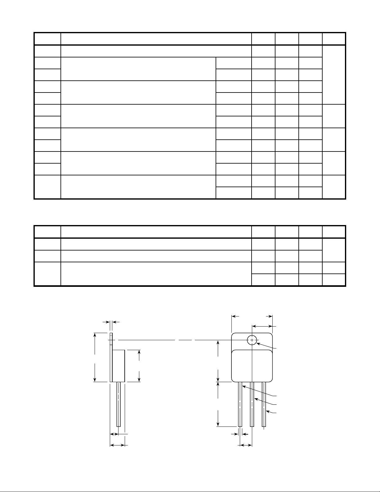
TO-258 Package Outline
1.14 (.045)
0.88 (.035)
21.21 (.835)
20.70 (.815)
13.84 (.545)
13.58 (.535)
17.96 (.707)
17.70 (.697)
19.05 (0.750)
12.70 (0.500)
MIN TYP MAX
17.65 (.695)
17.39 (.685)
0.22
6.1
8.89 (.350)
8.63 (.340)
4.19 (.165)
3.94 (.155)
Cathode
N.C.
Anode
UNIT
1.5
°C/W
40
oz
gm
lb•in
N•m
3.56 (.140) BSC
6.86 (.270)
6.09 (.240)
Dimensions in Millimeters and (Inches)
APT's devices are covered by one or more of the following U.S.patents: 4,895,810 5,045,903 5,089,434 5,182,234 5,019,522 5,262,336
053-4019 Rev - 2-2001
5,256,583 4,748,103 5,283,202 5,231,474 5,434,095 5,528,058
1.65 (.065)
1.39 (.055)
Dia. Typ.
3 Leads
5.08 (.200) BSC
 Loading...