

Advanced Power Technology APT APT30D30BCT Datasheet
1 3
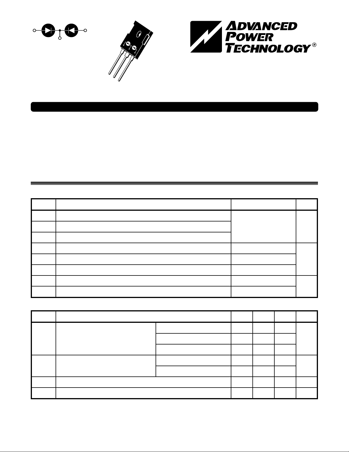
TO-247
2
1-Anode 1
2-Common Cathode
Back of Case -Cathode
3-Anode 2
1
2
3
APT30D30BCT 300V 30A
ULTRAFAST SOFT RECOVERY RECTIFIER DIODE
PRODUCT APPLICATIONS
• Anti-Parallel Diode
PRODUCT FEATURES
• Ultrafast Recovery Times
PRODUCT BENEFITS
• Low Losses
-Switchmode Power Supply
-Inverters
• Free Wheeling Diode
-Motor Controllers
-Converters
• Snubber Diode
• Uninterruptible Power Supply (UPS)
• Induction Heating
• High Speed Rectifiers
• Soft Recovery Characteristics
• Popular TO-247 Package
• Low Forward Voltage
• High Blocking Voltage
• Low Leakage Current
• Low Noise Switching
• Cooler Operation
• Higher Reliability Systems
• Increased System Power
Density
MAXIMUM RATINGS All Ratings Are Per Leg: TC = 25°C unless otherwise specified.
Symbol
V
R
V
RRM
V
RWM
IF(AV)
(RMS)
I
F
I
FSM
TJ,T
STG
T
L
Characteristic / Test Conditions (Single Diode)
Maximum D.C. Reverse Voltage
Maximum Peak Repetitive Reverse Voltage
Maximum Working Peak Reverse Voltage
Maximum Average Forward Current (T
RMS Forward Current
Non-Repetitive Forward Surge Current (TJ = 45°C, 8.3ms)
Operating and StorageTemperature Range
Lead Temperature: 0.063" from Case for 10 Sec.
= 110°C, Duty Cycle = 0.5)
C
APT30D30BCT
300
30
70
320
-55 to 150
300
UNIT
Volts
Amps
°C
STATIC ELECTRICAL CHARACTERISTICS
Symbol
V
I
RM
C
L
USA 405 S.W. Columbia Street Bend, Oregon 97702-1035 Phone: (541) 382-8028 FAX: (541) 388-0364
EUROPE Chemin de Magret F-33700 Merignac - France Phone: (33)5 5792 15 15 FAX: (33)5 56 47 97 61
Characteristic / Test Conditions (Single Diode)
Maximum Forward Voltage I
F
Maximum Reverse Leakage Current VR = VR Rated
Junction Capacitance, V
T
Series Inductance (Lead to Lead 5mm from Base)
S
= 150V
R
I
= 30A
F
= 60A
F
IF = 30A, TJ = 150°C
VR = VR Rated, TJ = 125°C
MIN TYP MAX
1.4
1.4
1.2
250
500
70
10
UNIT
Volts
µA
pF
nH
053-3003 Rev - 12-2000
DYNAMIC CHARACTERISTICS
APT30D30BCT
Symbol
t
rr1
t
rr2
t
rr3
t
fr1
t
fr2
I
RRM1
I
RRM2
Q
rr1
Q
rr2
V
fr1
V
fr2
diM/dt
Characteristic (Single Diode)
Reverse Recovery Time, I
= 1.0A, diF/dt = -15A/µs, VR = 30V, TJ = 25°C
F
Reverse Recovery Time TJ = 25°C
= 30A, diF/dt = -240A /µs, VR = 180V TJ = 100°C
I
F
Forward Recovery Time TJ = 25°C
= 30A, diF/dt = 240A/µs, VR = 180V TJ = 100°C
I
F
Reverse Recovery Current TJ = 25°C
= 30A, diF/dt = -240A /µs, VR = 180V TJ = 100°C
I
F
Recovery Charge T
= 25°C
J
IF = 30A, diF/dt = -240A /µs, VR = 180V TJ = 100°C
Forward Recovery Voltage T
= 30A, diF/dt = 240A/µs, VR = 180V TJ = 100°C
I
F
= 25°C
J
Rate of Fall of Recovery Current TJ = 25°C
= 30A, diF/dt = -240A /µs, VR = 180V TJ = 100°C
I
F
MIN TYP MAX
35 TBD
40
60
162
150
59
816
110
280
2.9
2.9
400
700
UNIT
ns
Amps
nC
Volts
A/µs
THERMAL AND MECHANICAL CHARACTERISTICS
qJC
qJA
Characteristic / Test Conditions (Single Diode)
Junction-to-Case Thermal Resistance
Junction-to-Ambient Thermal Resistance
Package Weight
T
Maximum Mounting Torque (Screw Type = 6-32 or 3mm Machine)
Symbol
R
R
W
Torque
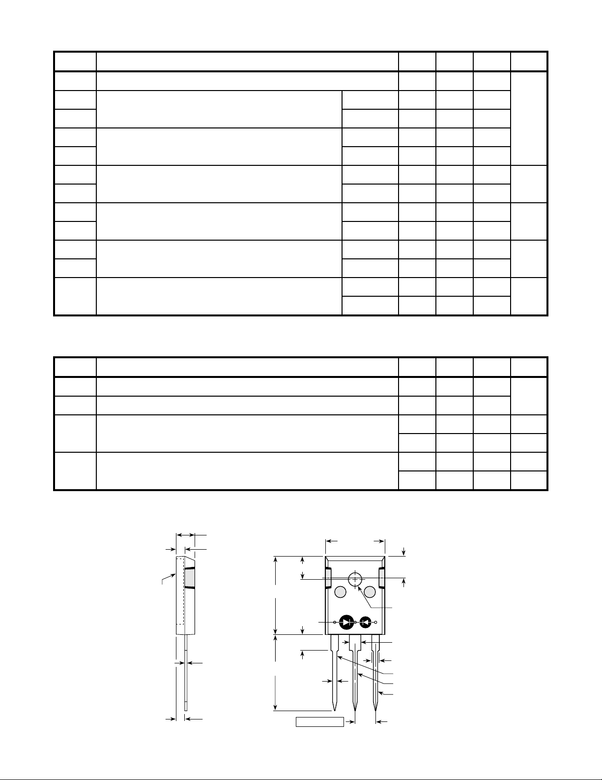
TO-247AD Package Outline
4.69 (.185)
5.31 (.209)
1.49 (.059)
2.49 (.098)
6.15 (.242) BSC
20.80 (.819)
Drain
21.46 (.845)
15.49 (.610)
16.26 (.640)
MIN TYP MAX
0.22
6.1
5.38 (.212)
6.20 (.244)
3.55 (.140)
3.81 (.150)
0.90
40
10
1.1
UNIT
°C/W
oz
gm
lb•in
N•m
053-3003 Rev- 12-2000
4.50 (.177) Max.
0.40 (.016)
0.79 (.031)
2.21 (.087)
2.59 (.102)
19.81 (.780)
20.32 (.800)
Dimensions in Millimeters and (Inches)
1.01 (.040)
1.40 (.055)
5.45 (.215) BSC
2-Plcs.
2.87 (.113)
3.12 (.123)
1.65 (.065)
2.13 (.084)
Anode 1
Cathode
Anode 2
 Loading...