

查询APT10M19SVR供应商
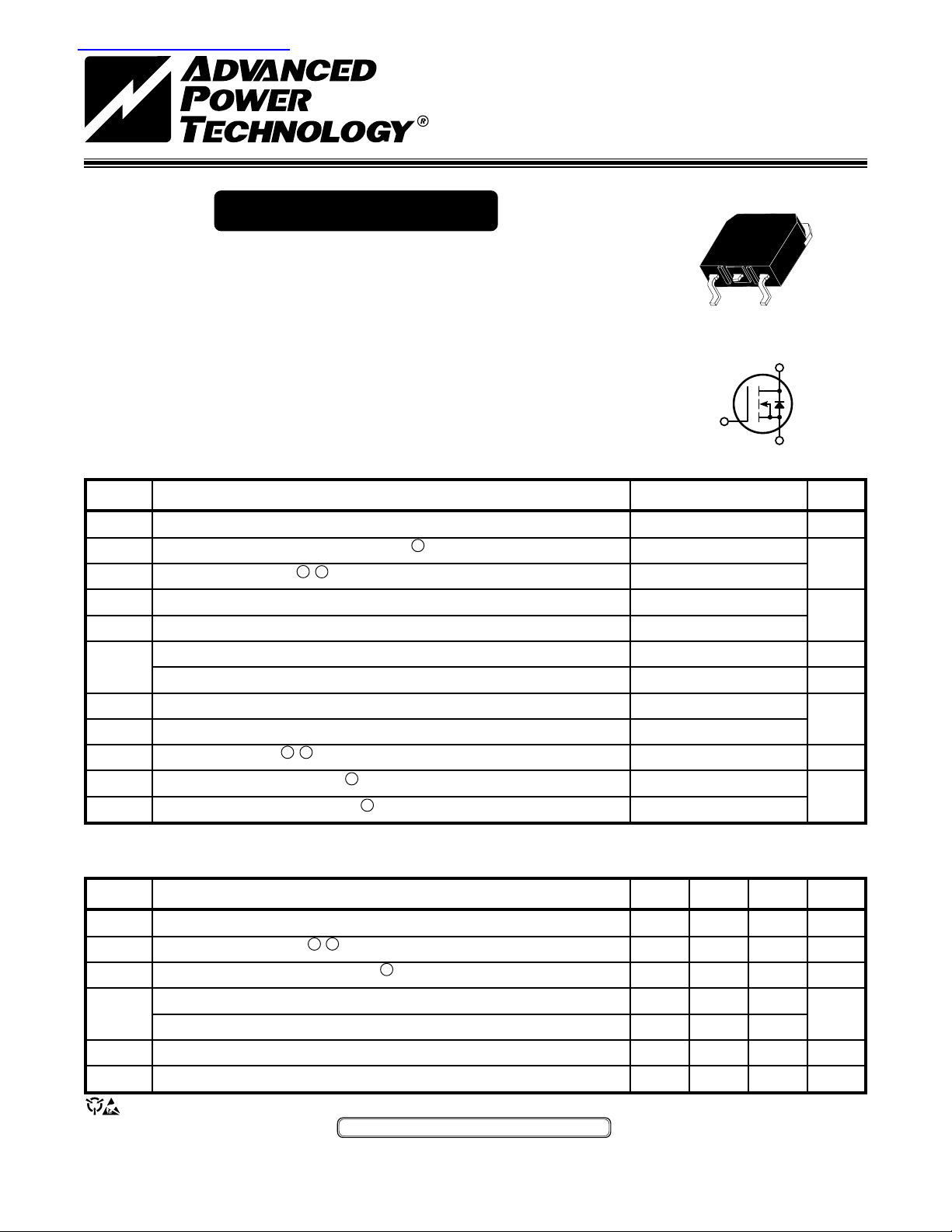
APT10M19SVR
100V 75A 0.019Ω
POWER MOS V
®
D3PAK
Power MOS V® is a new generation of high voltage N-Channel enhancement
mode power MOSFETs. This new technology minimizes the JFET effect,
increases packing density and reduces the on-resistance. Power MOS V
also achieves faster switching speeds through optimized gate layout.
• Faster Switching • 100% Avalanche Tested
3
• Lower Leakage • Surface Mount D
MAXIMUM RATINGS All Ratings: TC = 25°C unless otherwise specified.
Symbol
V
DSS
I
I
DM
V
V
GSM
P
TJ,T
T
I
AR
E
E
Parameter
Drain-Source Voltage
Continuous Drain Current @ T
D
Pulsed Drain Current
Gate-Source Voltage Continuous
GS
1 5
= 25°C
C
Gate-Source Voltage Transient
Total Power Dissipation @ TC = 25°C
D
Linear Derating Factor
Operating and Storage Junction Temperature Range
STG
Lead Temperature: 0.063" from Case for 10 Sec.
L
1 5
Avalanche Current
Repetitive Avalanche Energy
AR
Single Pulse Avalanche Energy
AS
(Repetitive and Non-Repetitive)
1
4
5
PAK Package
®
D
G
S
APT10M19SVR
100
UNIT
Volts
75
300
Amps
±30
±40
Volts
370
2.96
-55 to 150
Watts
W/°C
°C
300
75
Amps
30
1500
mJ
STATIC ELECTRICAL CHARACTERISTICS
Symbol
BV
I
D(on)
R
DS(on)
I
DSS
I
GSS
V
GS(th)
USA
405 S.W. Columbia Street Bend, Oregon 97702-1035 Phone: (541) 382-8028 FAX: (541) 388-0364
EUROPE
Avenue J.F. Kennedy Bât B4 Parc Cadéra Nord F-33700 Merignac - France Phone: (33) 5 579215 15 FAX: (33) 55647 97 61
Characteristic / Test Conditions
Drain-Source Breakdown Voltage (V
DSS
On State Drain Current
2 5
(V
Drain-Source On-State Resistance
Zero Gate Voltage Drain Current (VDS = V
Zero Gate Voltage Drain Current (V
Gate-Source Leakage Current (VGS = ±30V, V
= 0V, ID = 250µA)
GS
> I
DS
D(on)
2
(VGS = 10V, 0.5 I
= 0.8 V
DS
x R
DS(on)
, VGS = 0V)
DSS
DSS
DS
Max, VGS = 10V)
)
D[Cont.]
, VGS = 0V, TC = 125°C)
= 0V)
Gate Threshold Voltage (VDS = VGS, ID = 1.0mA)
CAUTION: These Devices are Sensitive to Electrostatic Discharge. Proper Handling Procedures Should Be Followed.
APT Website - http://www.advancedpower.com
MIN TYP MAX
100
75
24
0.019
250
1000
±100
UNIT
Volts
Amps
Ohms
µA
nA
Volts
050-5506 Rev C
DYNAMIC CHARACTERISTICS
Note:
Duty Factor D =
t
1
/
t
2
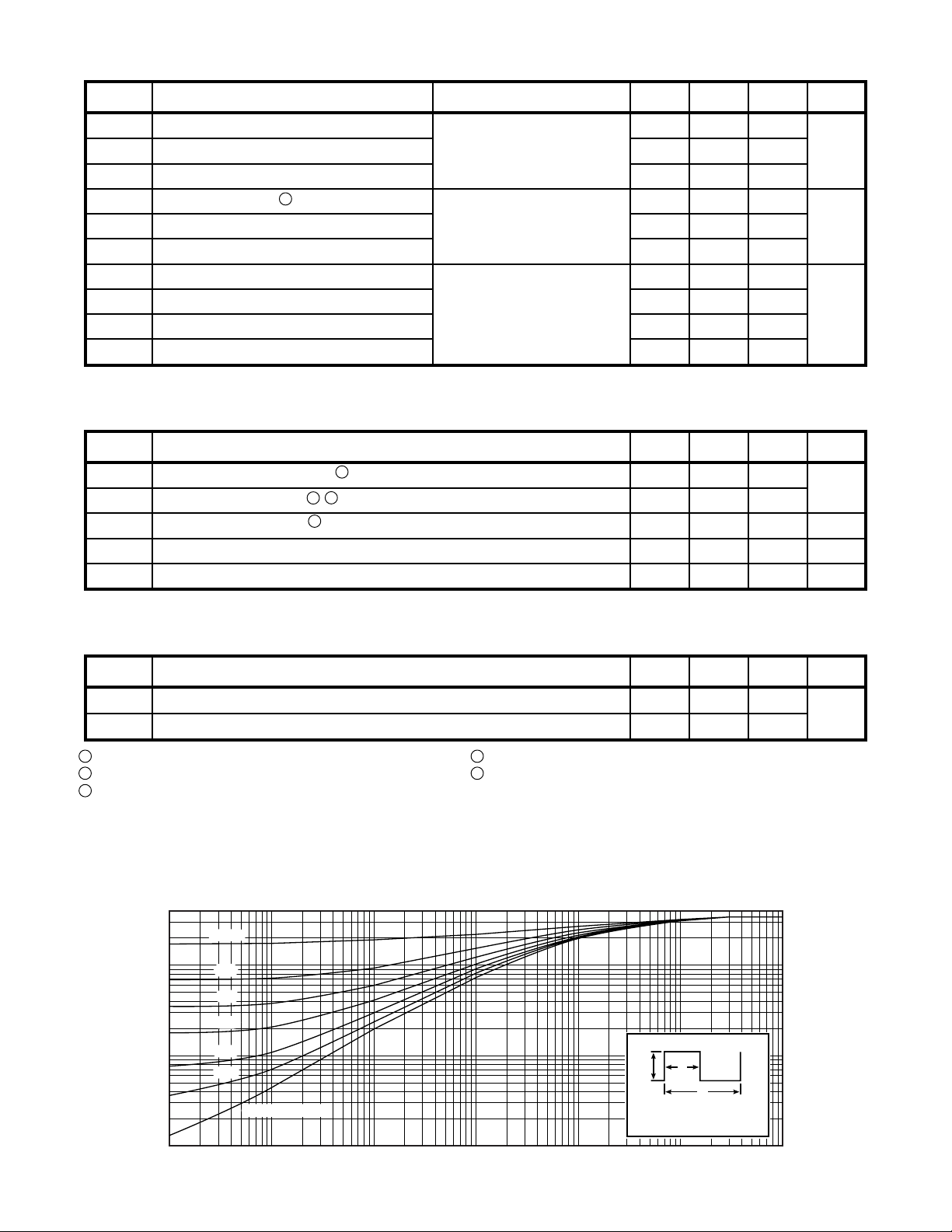
Peak TJ = PDM x Z
θJC
+ T
C
t
1
t
2
P
DM
APT10M19SVR
Symbol
C
iss
C
oss
C
rss
Q
g
Q
gs
Q
gd
t
d(on)
t
r
t
d(off)
t
f
Characteristic
Input Capacitance
Output Capacitance
Reverse Transfer Capacitance
Total Gate Charge
3
Gate-Source Charge
Gate-Drain ("Miller") Charge
Turn-on Delay Time
Rise Time
Turn-off Delay Time
Fall Time
Test Conditions
V
VDS = 25V
f = 1 MHz
V
GS
VDD = 0.5 V
ID = 0.5 I
VGS = 15V
VDD = 0.5 V
ID = I
D[Cont.]
RG = 1.6Ω
SOURCE-DRAIN DIODE RATINGS AND CHARACTERISTICS
Symbol
I
I
SM
V
t
Q
Characteristic / Test Conditions
Continuous Source Current (Body Diode)
S
Pulsed Source Current
Diode Forward Voltage 2 (VGS = 0V, IS = -I
SD
Reverse Recovery Time (IS = -I
rr
Reverse Recovery Charge (I
rr
1 5
5
(Body Diode)
, dlS/dt = 100A/µs)
D[Cont.]
S
= -I
, dlS/dt = 100A/µs)
D[Cont.]
D[Cont.]
)
= 0V
GS
= 10V
D[Cont.]
DSS
@ 25°C
DSS
@ 25°C
MIN TYP MAX
5100 6120
1900 2660
800 1200
200 300
40 60
92 180
16 32
40 40
50 75
20 40
MIN TYP MAX
75
300
1.3
200
1.4
UNIT
pF
nC
ns
UNIT
Amps
Volts
ns
µC
050-5506 Rev C
THERMAL CHARACTERISTICS
Symbol
R
θJC
R
θJA
1
Repetitive Rating: Pulse width limited by maximum T
2
Pulse Test: Pulse width < 380 µS, Duty Cycle < 2%
3
See MIL-STD-750 Method 3471
APT Reserves the right to change, without notice, the specifications and information contained herein.
Characteristic
Junction to Case
Junction to Ambient
0.4
0.1
0.05
0.01
0.005
, THERMAL IMPEDANCE (°C/W)
JC
θ
Z
0.001
-5
10
4
j
D=0.5
0.2
0.1
0.05
0.02
0.01
SINGLE PULSE
-4
10
FIGURE 1, MAXIMUM EFFECTIVE TRANSIENT THERMAL IMPEDANCE, JUNCTION-TO-CASE vs PULSE DURATION
-3
10
RECTANGULAR PULSE DURATION (SECONDS)
Starting T
5
The maximum current is limited by lead temperature.
-2
10
+25°C, L = 0.53mH, R
j
=
-1
10
MIN TYP MAX
0.34
40
25Ω, Peak IL = 75A
G
=
1.0 10
UNIT
°C/W

APT10M19SVR
200
160
VGS=9V, 10V & 15V
8V
200
160
VGS=15V
10V
9V
8V
120
120
7V
80
6.5V
80
6.5V
6V
40
, DRAIN CURRENT (AMPERES)
D
5.5V
5V
40
, DRAIN CURRENT (AMPERES)
D
4.5V
0
01020304050 012345
VDS, DRAIN-TO-SOURCE VOLTAGE (VOLTS) VDS, DRAIN-TO-SOURCE VOLTAGE (VOLTS)
0
5.5V
4.5V
FIGURE 2, TYPICAL OUTPUT CHARACTERISTICS FIGURE 3, TYPICAL OUTPUT CHARACTERISTICS
125
100
VDS> ID (ON) x RDS (ON)MAX.
250µSEC. PULSE TEST
75
@ <0.5 % DUTY CYCLE
TJ = -55°C
TJ = +25°C
TJ = +125°C
50
25
, DRAIN CURRENT (AMPERES) I
D
0
02468 050100150200250300
V
GS
FIGURE 4, TYPICAL TRANSFER CHARACTERISTICS FIGURE 5, RDS(ON) vs DRAIN CURRENT
TJ = +125°C
TJ = +25°C
TJ = -55°C
, GATE-TO-SOURCE VOLTAGE (VOLTS) ID, DRAIN CURRENT (AMPERES)
80
2.00
1.80
NORMALIZED TO
V
= 10V @ 0.5 ID [Cont.]
GS
1.60
1.40
1.20
1.00
(ON), DRAIN-TO-SOURCE ON RESISTANCE I
0.80
DS
VGS=10V
VGS=20V
1.15
7V
6V
5V
60
1.10
1.05
40
1.00
20
, DRAIN CURRENT (AMPERES) I
D
0
25 50 75 100 125 150 -50 -25 0 25 50 75 100 125 150
T
, CASE TEMPERATURE (°C) TJ, JUNCTION TEMPERATURE (°C)
FIGURE 6, MAXIMUM DRAIN CURRENT vs CASE TEMPERATURE FIGURE 7, BREAKDOWN VOLTAGE vs TEMPERATURE
2.00
C
ID = 0.5 ID [Cont.]
VGS = 10V
1.75
1.50
1.25
1.00
(NORMALIZED)
0.75
(ON), DRAIN-TO-SOURCE ON RESISTANCE I
0.50
DS
-50 -25 0 25 50 75 100 125 150 -50 -25 0 25 50 75 100 125 150
R
T
, JUNCTION TEMPERATURE (°C) TC, CASE TEMPERATURE (°C)
J
FIGURE 8, ON-RESISTANCE vs. TEMPERATURE FIGURE 9, THRESHOLD VOLTAGE vs TEMPERATURE
0.95
, DRAIN-TO-SOURCE BREAKDOWN R
DSS
0.90
1.2
1.1
1.0
0.9
0.8
(NORMALIZED) VOLTAGE (NORMALIZED)
(TH), THRESHOLD VOLTAGE BV
0.7
GS
V
0.6
050-5506 Rev C

300
OPERATION HERE
LIMITED BY RDS (ON)
100
50
10
5
TC =+25°C
, DRAIN CURRENT (AMPERES)
D
TJ =+150°C
SINGLE PULSE
100µS
1mS
10mS
100mS
DC
15,000
10,000
5,000
1,000
C
oss
C
iss
APT10M19SVR
C
iss
C
oss
C
rss
1
1 5 10 50 100 .01 .1 1 10 50
VDS, DRAIN-TO-SOURCE VOLTAGE (VOLTS) VDS, DRAIN-TO-SOURCE VOLTAGE (VOLTS)
FIGURE 10, MAXIMUM SAFE OPERATING AREA FIGURE 11, TYPICAL CAPACITANCE vs DRAIN-TO-SOURCE VOLTAGE
20
ID = 0.5 ID [Cont.]
16
12
8
4
, GATE-TO-SOURCE VOLTAGE (VOLTS) I
GS
V
0
0 50 100 150 200 250 300 350 0 0.4 0.8 1.2 1.6 2.0
Q
, TOTAL GATE CHARGE (nC) VSD, SOURCE-TO-DRAIN VOLTAGE (VOLTS)
FIGURE 12, GATE CHARGES vs GATE-TO-SOURCE VOLTAGE FIGURE 13, TYPICAL SOURCE-DRAIN DIODE FORWARD VOLTAGE
g
VDS=20V
VDS=50V
VDS=80V
500
200
100
50
10
, REVERSE DRAIN CURRENT (AMPERES) C, CAPACITANCE (pF)
DR
I
T
=+150°C T
J
5
1
=+25°C
J
D3PAK Package Outline
4.98 (.196)
5.08 (.200)
1.47 (.058)
1.57 (.062)
15.95 (.628)
16.05 (.632)
1.04 (.041)
1.15 (.045)
13.41 (.528)
13.51 (.532)
Drain
(Heat Sink)
13.79 (.543)
13.99 (.551)
1.27 (.050)
1.40 (.055)
1.98 (.078)
2.08 (.082)
0.46 (.018)
0.56 (.022)
0.020 (.001)
0.178 (.007)
2.67 (.105)
2.84 (.112)
Revised
4/18/95
{3 Plcs}
1.22 (.048)
1.32 (.052)
5.45 (.215) BSC
{2 Plcs.}
Source
Drain
Gate
Dimensions in Millimeters (Inches)
APT's devices are covered by one or more of the following U.S.patents: 4,895,810 5,045,903 5,089,434 5,182,234 5,019,522 5,262,336
050-5506 Rev C
5,256,583 4,748,103 5,283,202 5,231,474 5,434,095 5,528,058
Revised
8/29/97
11.51 (.453)
11.61 (.457)
3.81 (.150)
4.06 (.160)
(Base of Lead)
Heat Sink (Drain)
and Leads
are Plated
 Loading...